Cable assembly
What is a cable assembly?
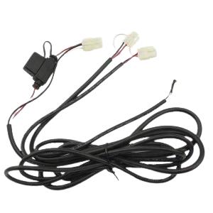
A cable assembly is a combination of one or more electrical cables that are bound together with connectors or terminals at the ends to create a single, organized, and functional unit. These assemblies are used in various industries, including electronics, telecommunications, automotive, aerospace, and many others. The primary purpose of a cable assembly is to transmit electrical signals or power from one point to another, ensuring that the connections are secure, reliable, and well-protected.
Characteristics of cable assemblies:
1. Cables
These are the core elements of a cable assembly. They can be made of copper, aluminum, or other conductive materials and are used to transmit electrical signals, power, or data.
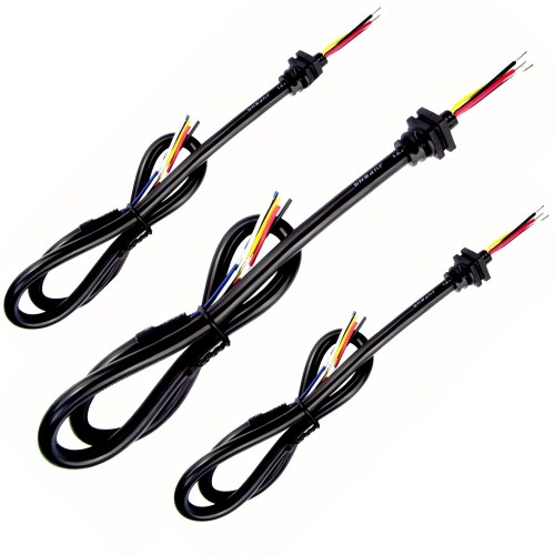
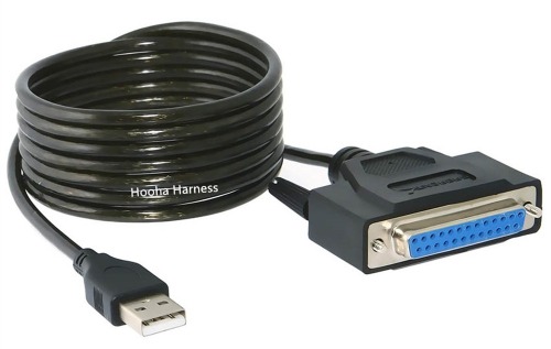
We say cable assembly, from a broad definition, refers to the assembly of wire harnesses, as wire harnesses are sometimes also called cable harnesses. Therefore, the cable harness assembly, from a broad definition, is also called wire harness assembly. However, from a narrow definition, we tend to refer only to the assembly of cables, which specifically refer to shielded cables consisting of multiple core electronic wires. In the data cable category, the cable assembly is the most widely used, such as the USB cable we commonly use, which is actually a type of cable assembly. The VGA cable, or D-sub cable also uses multi-core shielded wires, and cables themselves have a protective sheath, so they have a higher degree of integration and a more streamlined appearance.
2. Connectors and Terminals
Connectors are attached to the ends of the cables to enable easy and secure connections to other devices or components. There are various types of connectors, including USB, HDMI, D-sub, audio jacks, and custom connectors specific to certain applications.
Terminals are similar to connectors but are often simpler in design. They are used for attaching wires to a circuit board or other components.
3. Insulation
Insulating materials, such as PVC, rubber, or Teflon, are used to cover and protect the wires within the cable assembly. Insulation helps prevent electrical interference, short circuits, and damage from external factors like moisture or heat.
It should be noted that if the cable assembly has a molded section, we usually use PVC or TPE compounds for molding, not rubber or Teflon compounds (due to equipment limitations). If the cable uses rubber or Teflon insulation, the molding compound will not bond well with these materials, resulting in poor waterproof performance. Of course, even with PVC compounds, the molded section may not fully bond during the overmolding process. However, the bonding effect will be better if the same type of compound is used.
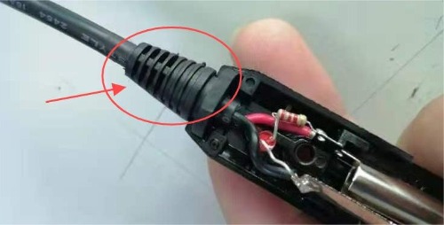
4. Strain Relief
Strain relief components are often included to prevent damage to the cables or wires at the points where they connect to connectors or terminals. These can be in the form of molded boots or flexible materials.
The Strain Relief, commonly known as SR, is extensively utilized in cable assemblies. It can be directly integrated with the connector molding to safeguard against wire breakage or employed at the box edge to securely fasten and prevent external forces from tearing apart the core wire.
5. Shielding
In some cable assemblies, shielding layers may be added to reduce electromagnetic interference (EMI) or radio frequency interference (RFI). Shielding can be in the form of metal foil or braided wire.
When selecting cables for a product, another important reason is the need for a shielding layer to prevent interference from external signals. Cables can highly integrate the shielding layer into the jacket, and the shielding layer is usually a metal braid, aluminum foil, or a ground wire, all of which have shielding properties. In the processing of cables, this type of shielding layer increases the difficulty of processing. Sometimes the shielding layer can be used as a core wire, and sometimes it does not need to be connected to the connector at both ends, in which case it needs to be cut off.
How to do the Ethernet Cable Assembly?
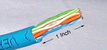
Cut the plastic sheath approximately one inch (2.5 cm) from the end of the cable. With practice, you can use the razor blade on the crimping tool to accomplish this.
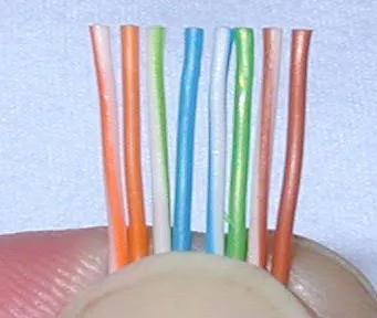
Unwind and match the similar colors. Pinch the wires between your fingers and straighten them out as shown. The color order is crucial. Use scissors to cut the eight wires to half an inch (1.3 cm) from the sleeve to the end.
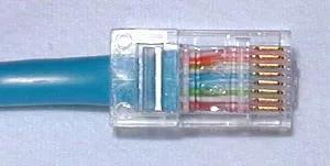
Carefully push all eight unstripped colored wires into the connector. Note the position of the blue plastic sleeve. Also, note how the wires go all the way to the end.
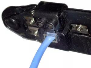
Gently insert the connector into the Ethernet crimper and firmly squeeze the handles. The copper splicing tabs will pierce through all eight wires, while a locking tab secures the blue plastic sleeve for a snug fit. Once removed from the crimper, that end of the cable is ready to use.
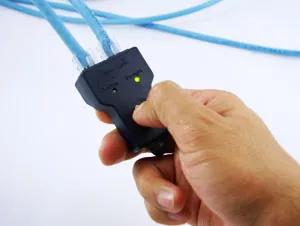
Do the same way for the other side of the connectors, and test it to make sure connect it correctly.
Network cable is also a kind of cable, from the processing steps of the above network cable, we can also know the general processing steps of the cable assembly, but the processing of the above network cable, you can manually complete. As a cable assembly manufacturer, industrial cable assembly processing is usually a mechanical operation, that is, each step is completed using machinery and equipment to ensure the accuracy of the size.
Cable Assembly Products Cases
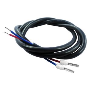
2 core jacket cable terminal wire cable assembly
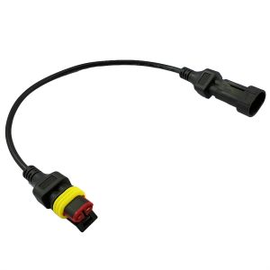
AMP superseal 1.5 2 Pin male to female cable assembly
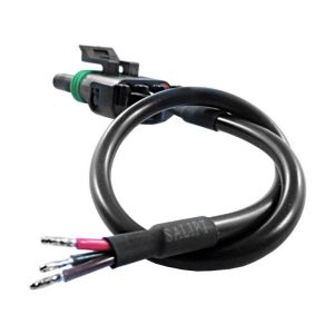
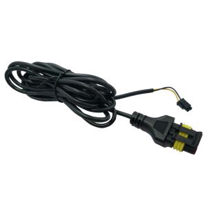
AMP Superseal 1.5 2P connector overmold cable assembly
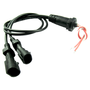
Aptiv 12015793 3 Pin connector Cable Assembly
Custom Cable Assembly
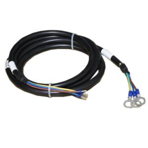
Custom Power Cable Assembly
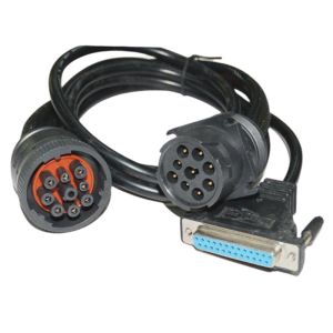
Deutsch HD10 9 Pin Connector Cable Assembly
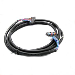
LVDS Cable Assembly
AMP superseal 3P custom cable assembly
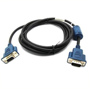
VGA Cable Assembly
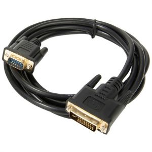
VGA to DVI cable assembly
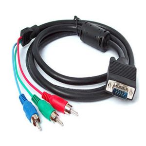
VGA to RCA Cable Assembly
How to customize your cable assembly?
Send us your sample or drawing/schematic for quote price→ Feedback with quotation(1~3 days) → Confirm quotation → Arrange sample you for approval→ [Make mold if needed (7 days) →Mold test] → Making samples(1~3 days)→Samples test(Approval) →place order for Mass production(2~3 weeks)→Quality checking→Packing →Delivery →After Service →Repeat Order.
