Engine Wiring Harness: What You Need to Know
Part 1 what is engine wire harness
An engine wire harness is a structured assembly of cables, wires, connectors, and terminals designed to transmit power and signals throughout a vehicle’s engine and related systems. It acts as the central nervous system, linking critical components like the ECU (Engine Control Unit), sensors, fuel injectors, ignition systems, alternators, and more. By organizing multiple wires into a single bundled unit, it ensures efficient electrical distribution while minimizing the risk of shorts, interference, or damage.
Key Features & Functions:
Durability: Engineered to withstand extreme heat, vibrations, moisture, and chemical exposure.
Safety: Flame-retardant coatings and abrasion-resistant sleeves prevent fires and wear.
Customization: Tailored to fit specific engine layouts (e.g., turbocharged, hybrid, or EV powertrains).
Efficiency: Optimizes space by consolidating wires, simplifying installation and maintenance.
Part 2 Components In An Engine Harness
The engine harness is a vital electrical network in modern vehicles, serving as the central nervous system that links critical engine components like sensors, actuators, and control units. By transmitting power and signals, it ensures optimal engine performance, fuel efficiency, and emission control. Key elements include wires, connectors, fuses, and relays, all designed to withstand heat, vibration, and harsh conditions. Proper maintenance of the harness—such as inspecting for frayed wires or corroded terminals—can prevent electrical failures. Understanding its structure and function aids in diagnosing issues like misfires or warning lights, ultimately enhancing vehicle reliability and longevity.
Wires And Connectors
The engine harness comprises multiple wires and connectors, transmitting electrical signals across engine components. Connectors provide secure, stable connections to prevent signal interruptions. This network ensures reliable communication between sensors, actuators, and control modules for optimal engine performance.
Sensors And Actuators
Sensors play a crucial role in tracking engine performance by collecting and transmitting real-time data to the vehicle's control unit. This information enables precise adjustments to optimize engine efficiency.
Actuators execute commands from the control system, directly managing engine operations. Key examples include:
Fuel Injectors: Precisely meter and deliver fuel to the combustion chamber.
Throttle Actuators: Adjust airflow by regulating the throttle valve position.
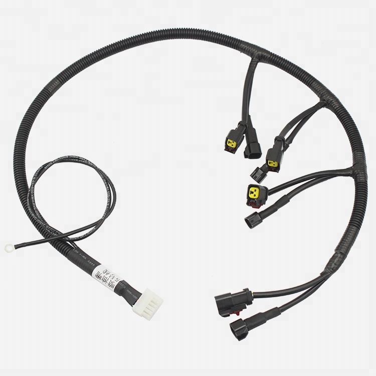
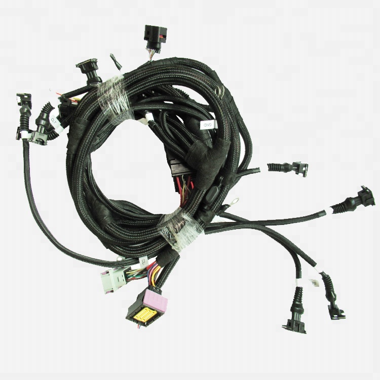
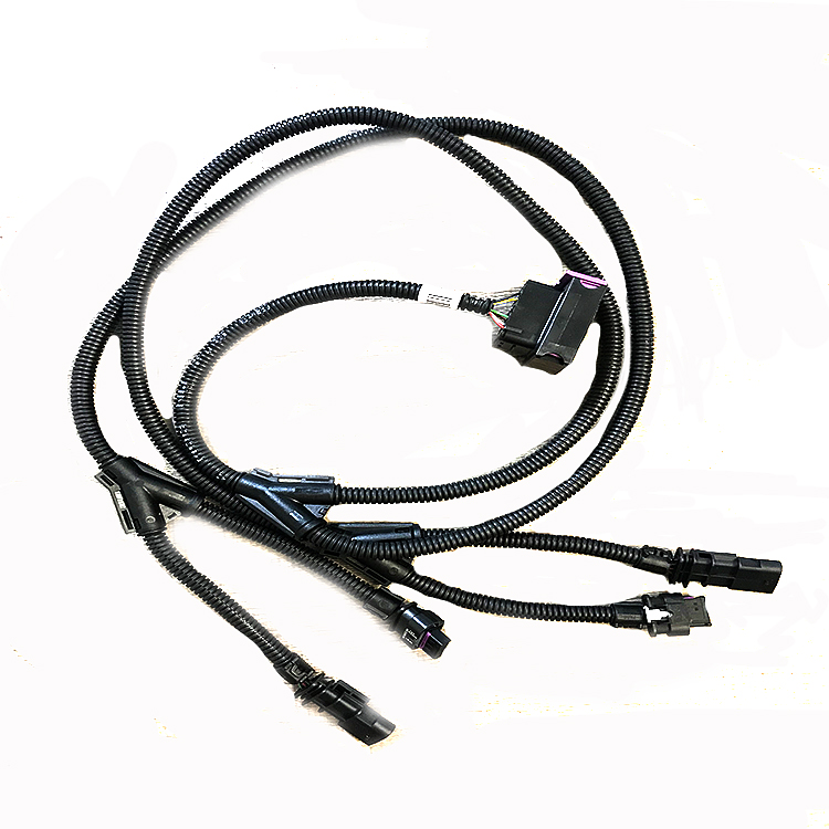
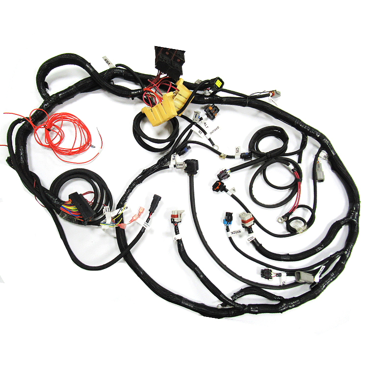
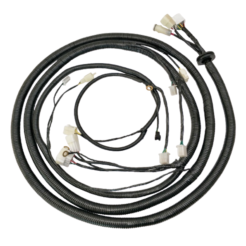
Part 3 Show some parts of product we made
Part4 The Consequences and Solutions for a Faulty Engine Wiring Harness
A malfunctioning engine wiring harness can have far-reaching implications that extend beyond simple performance issues. When critical electrical signals are interrupted or corrupted, the vehicle's engine management system cannot function properly, potentially leading to:
Operational Failures:
Complete engine stalling at critical moments (such as during highway driving)
Intermittent starting problems that worsen over time
Erratic engine behavior including misfires and rough idling
Safety Hazards:
Electrical short circuits that may damage sensitive electronic components
Potential fire risks from overheating or sparking in damaged wiring
Compromised vehicle safety systems that rely on proper electrical communication
Financial Implications:
Progressive damage to connected components due to improper voltage/current
Significantly higher repair costs when multiple systems are affected
Potential voiding of manufacturer warranties if improper repairs are attempted
The professional replacement process involves these key steps:
Preparatory Phase:
Complete vehicle power-down procedure (including battery disconnection)
Diagnostic scan to document existing fault codes
Creation of connection mapping for reference during installation
Removal Process:
Systematic disconnection of all harness attachments
Careful extraction from tight engine compartment spaces
Inspection of routing paths for potential wear points
Installation Protocol:
Precise routing of new harness following factory specifications
Secure connection of all terminals and connectors
Application of protective coatings or wraps in high-heat areas
Post-Installation Verification:
Comprehensive electrical system testing
Component-by-component functionality check
Final diagnostic scan to confirm proper system communication
Some maintenance tips on engine wiring harness
Scheduled Visual Inspections
Conduct thorough inspections every 6 months or 10,000 miles
Pay special attention to vehicles operating in extreme conditions:
High-temperature environments
Coastal areas with salt exposure
Off-road or dusty operating conditions
Inspection checklist should include:
Insulation integrity checks
Connector corrosion assessment
Abrasion points examination
Professional Cleaning Procedures
Use electrical contact cleaner for terminal connections
Remove debris using compressed air (30-50 psi maximum)
For heavy contamination:
Disconnect battery before cleaning
Use soft bristle brushes
Apply dielectric grease after cleaning
Advanced Protection Measures
Install heat-resistant sleeving in high-temperature zones:
Near exhaust manifolds
Turbocharger areas
Engine block proximity
Utilize abrasion-resistant loom in friction-prone areas:
Where harness passes through body panels
Near moving components
Suspension and steering areas
Consider additional waterproofing for:
Underbody wiring runs
Engine bay connections
Sensor wiring
