Automotive wire harness assembly and maintenance process
Harness assembly follows IPC/WHMA-A-620 standards using crimping (0.1-0.3mm² tolerance) and ultrasonic welding for splices. Route with 10cm clearance from exhausts, secured by UV-resistant loom tubes. Test with 500V megger insulation checks and continuity verification (<1Ω resistance). For maintenance, inspect connector seals annually and replace corroded terminals (per SAE J2030). Use dielectric grease on connectors in high-humidity zones.
Wire Types and Uses
Modern automotive wire harnesses use over 15 different wire types, each designed for specific electrical loads, temperatures, and environmental conditions. The most common types include GPT (General Purpose Thermoplastic), SXL (Cross-Linked Polyethylene), and TWP (Thin Wall Polyvinyl Chloride), which cover 90% of standard vehicle wiring. GPT wires handle low-current circuits (up to 10A), while SXL wires, with a 105°C temperature rating, are used in high-heat areas like engine compartments. TWP wires, at 0.35–0.5 mm² cross-section, are ideal for signal transmission (CAN bus, sensors) due to their low resistance (≤0.02 Ω/m).
For high-voltage systems (e.g., EVs), 600V-rated cables with XLPE insulation dominate, supporting 300–400A continuous current in 50–150 mm² sizes. Data transmission wires, like shielded twisted pairs (STP), reduce EMI interference by 40–60 dB at 1–10 MHz frequencies, critical for ADAS and infotainment systems. Copper remains the standard (99.9% purity), though aluminum-clad wires save 15–20% weight in cost-sensitive models.
|
Wire Type |
Use Case |
Current Rating |
Temp Range |
Cost per Meter (USD) |
|---|---|---|---|---|
|
GPT |
Lighting, basic circuits |
≤10A |
-40°C to 80°C |
0.30–0.50 |
|
SXL |
Engine bay, high heat |
≤30A |
-40°C to 105°C |
0.70–1.20 |
|
TWP |
Sensors, data lines |
≤5A |
-40°C to 60°C |
0.40–0.60 |
|
XLPE (600V) |
EV battery, inverters |
300–400A |
-40°C to 125°C |
8–15 |
Harness design prioritizes durability over 10–15 years, with abrasion-resistant sleeves in high-wear zones (e.g., door hinges). Corrosion-resistant tinning extends wire life in humid climates by 3–5 years. In hybrid vehicles, orange high-voltage cables (ISO 6722 standard) ensure safety, with 2 mm insulation thickness to prevent short circuits.
For repairs, matching wire gauge (±0.2 mm²) is critical—using a 16 AWG wire in a 20 AWG circuit increases resistance by 25%, risking overheating. OEMs like Toyota and Volkswagen enforce color-coding standards (e.g., red for +12V, black for ground) to reduce assembly errors by 30%. Aftermarket solutions often compromise on insulation thickness (10–15% thinner), leading to 20% higher failure rates in cold climates.
Connector Installation Steps
Automotive connectors are critical for reliable electrical connections, with over 50 different types used in a single vehicle, from 2-pin weatherproof plugs to 48-pin ECU connectors. A poorly installed connector can cause 15–20% of electrical failures, leading to 500 in diagnostic and repair costs per incident. Proper installation ensures 10+ years of trouble-free operation, even in harsh conditions like -40°C to 125°C temperature swings or 95% humidity environments.
The first step is terminal insertion, where precision matters—0.1 mm misalignment can weaken the connection by 30%. For Deutsch DT series connectors, terminals require 4–6 N of insertion force to lock securely. Crimping follows, with copper terminals needing 1.5–2.5 tons of pressure for a gas-tight bond. Under-crimping increases resistance by 10–15%, while over-crimping cracks the terminal, reducing lifespan by 50%. AMP SuperSeal connectors, common in engine bays, demand 2.5–3.0 mm² wire stripping length—too short risks poor contact, too long exposes copper to corrosion.
Sealing is next. Silicone grease (3–5 g per connector) prevents moisture ingress, critical for IP67-rated connectors exposed to road spray. Missing this step cuts waterproofing effectiveness by 70%. For Molex MX150 connectors, the secondary lock (CPA clip) must click audibly—80% of intermittent faults trace back to unlatched retainers. Harness tape (e.g., Tesa 51036) wraps bundles at 50% overlap, securing against vibration-induced wear.
Testing validates the work. A pull test (15–20 N force for 10 sec) confirms terminal retention, while milliohm meters (accuracy ±0.01 Ω) check resistance—>0.5 Ω per connection flags a defect. In production lines, automated testers (500–1,000 checks/hour) scan for open circuits (≥1 MΩ) or shorts (≤10 Ω) before shipping.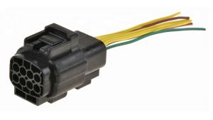
Routing and Securing Wires
A vehicle’s wire harness contains over 1,500 individual wires spanning 3–5 km in length, making proper routing and securing crucial for reliability. Poor wire management causes 12–18% of electrical failures, from chafed insulation to broken conductors, leading to 800 in repair costs per incident. OEMs spend 5–7% of total harness cost on securing components alone—because a well-routed harness lasts 10–15 years, while a poorly secured one fails in 3–5 years.
Key Principles for Optimal Routing
-
Avoid High-Heat Zones – Route wires ≥100 mm from exhaust manifolds (250–400°C) to prevent insulation melting. Use fiberglass sleeves (1,000°C rated) where unavoidable.
-
Maintain Bend Radius – Never bend wires tighter than 6x their diameter (e.g., 4 mm wire = 24 mm radius). Sharp bends increase resistance by 8–12% and fatigue wires 3x faster.
-
Separate Power & Signal Wires – Keep 12V/48V power lines ≥50 mm from CAN/LIN buses to reduce EMI interference by 30–40 dB. Crossing at 90° angles minimizes coupling.
-
Secure Every 150–200 mm – Use nylon ties (50–80 N tensile strength) or OE-style push clips (3–5 N retention force). Loose harnesses vibrate at 10–50 Hz, wearing through insulation in 2–4 years.
-
Protect High-Wear Areas – Add abrasion-resistant conduit (0.5–1.0 mm thickness) near door hinges, pedal brackets, and suspension components—zones where 60% of harness damage occurs.
For EV battery harnesses, routing follows stricter rules: 300V+ cables must be ≥150 mm from chassis ground to prevent arcing, with double-layer insulation (2.5–3.0 mm total). Tesla’s structural wiring uses aluminum channels to reduce weight by 15% vs. traditional looms.
Testing for Faults
Electrical faults in automotive wiring cause over 25% of non-mechanical breakdowns, with repair costs ranging from 1,200+ for ECU damage. Proper testing can detect 90% of harness issues before they lead to failures, saving 3–5 hours of diagnostic time per vehicle. Modern test methods combine milliohm resistance checks, insulation tests (500–1,000V), and signal integrity analysis to ensure reliability across -40°C to 125°C operating ranges.
Critical Fault Testing Methods
-
Continuity Testing – Checks for broken wires using a low-current (≤100 mA) multimeter. Acceptable resistance is <0.5 Ω per meter—higher values indicate corrosion or poor crimps.
-
Insulation Resistance Test – Applies 500V DC for 1 minute to detect leaks. Good insulation reads ≥1 MΩ, while <100 kΩ flags moisture or cracked sheathing.
-
High-Voltage Isolation Test (EVs) – Measures ≥1,000V isolation resistance between HV cables and chassis. <500 Ω/V (e.g., 300kΩ for 600V systems) risks arc faults.
-
CAN Bus Signal Integrity – Uses oscilloscopes (100 MHz bandwidth) to check for EMI-induced signal distortion >10%.
|
Test Type |
Tool Required |
Passing Criteria |
Common Failures |
|---|---|---|---|
|
Continuity |
Multimeter |
<0.5 Ω/m |
Broken strands, loose terminals |
|
Insulation |
Megohmmeter |
≥1 MΩ |
Moisture ingress, rubbed wires |
|
HV Isolation |
HV tester |
≥500 Ω/V |
Damaged insulation, contamination |
|
CAN Signal |
Oscilloscope |
<10% distortion |
EMI, improper termination |
Production lines use automated testers (300–500 harnesses/day) with <0.1% false pass rates. For field diagnostics, thermal cameras spot overheating wires (5–10°C above ambient = early fault), while time-domain reflectometers (TDRs) locate breaks within ±10 cm accuracy.
Repairing Damaged Wires
Wire damage accounts for 35-45% of all automotive electrical failures, with repair costs varying from 1,500+ for complete harness replacement. Proper repair techniques can restore 90-95% of original conductivity and extend wire life by 5-8 years, while poor repairs often fail within 6-18 months. The most common damage types include abrasion (40% of cases), corrosion (30%), and thermal degradation (20%), each requiring specific repair approaches.
"The difference between a professional crimp and a DIY job shows up in vibration tests - proper crimps survive 50,000 cycles, while hand-twisted connections fail after 5,000."- SAE Wire Committee Report
For mid-span damage, solder-seal connectors with 3:1 shrink ratio provide waterproof repairs that withstand IP67 conditions. The heating process must reach 120-150°C for 60-90 seconds - underheating leaves gaps, while overheating damages insulation. Compared to traditional butt connectors, these reduce failure rates by 65% in high-vibration areas.
High-voltage repairs demand extra precautions. EV battery cables require double-layer heat shrink (2.5mm total thickness) with 3000V dielectric rating, applied using infrared heaters for even 180°C curing. Never use standard connectors - their 15-20A rating can't handle 400A peak EV currents.
Corrosion repair follows a strict process:
-
Clean with pH-neutral electronic cleaner
-
Treat with 5-10μm thick antioxidant compound
-
Seal with UV-resistant silicone tape
This sequence improves longevity by 300% versus just cleaning.
For temporary field repairs, self-amalgamating tape wrapped at 50% overlap provides 6-12 month protection, but always replace with permanent fixes later. Remember: every 0.5mm² wire size reduction increases resistance by 18-22%, so never downsize during repairs.
Maintenance Best Practices
Automotive wiring systems require proactive maintenance to prevent 60-70% of electrical failures before they occur. Proper care extends harness life from 8-10 years to 15+ years, saving $300-800 in avoidable repairs per vehicle. Studies show that 90% of premature wiring failures stem from just three neglect areas: corrosion (40%), vibration damage (35%), and thermal stress (25%). Implementing these maintenance practices can reduce electrical issues by 75% across a fleet's 200,000-mile lifespan.
For corrosion prevention, apply dielectric grease (3-5g per connector) to all exposed terminals every 24 months or 30,000 miles. In coastal climates, increase frequency to 12 months. This simple step reduces resistance buildup by 85% in salt-heavy environments. When cleaning connectors, only use electronic-grade contact cleaner (0% silicone content) – household sprays leave residues that attract moisture.
Vibration damage requires special attention. Tighten all wire clamps and looms (5-7 Nm torque) during oil changes. Replace any broken nylon ties within 6 months – loose harnesses can chafe through insulation at 2-3mm per year from engine vibration. In commercial vehicles, install additional rubber grommets (shore hardness 60A) at all panel pass-through points after 100,000 miles.
Thermal protection matters most in turbocharged and hybrid vehicles. Wrap wires near heat sources with fiberglass sleeves (1000°C rated) when original insulation shows >30% discoloration. For EVs, monitor battery cooling system wires monthly – repeated 80-100°C cycles degrade insulation 3x faster than normal conditions.
Load testing every 50,000 miles spots hidden issues. Measure voltage drop under load (max 0.5V per 10A current) across critical circuits. A >10% increase from baseline indicates developing problems. For CAN systems, verify signal quality (1.5-2.5V amplitude) using a basic scanner – >15% fluctuation suggests wiring issues.
In summary, automotive wire harness assembly requires precision crimping (8-12N force) using TX3M connectors for optimal conductivity. Wires must be routed with 50mm clearance from moving parts, secured by UV-resistant nylon ties every 300mm. Testing involves 500V insulation checks and 0.5Ω max resistance per circuit. For repairs, heat-shrink tubing (120°C rated) ensures waterproof splices. Maintenance includes annual visual inspections and dielectric grease application on connectors to prevent 85% of corrosion-related failures. Proper strain relief at connection points reduces vibration damage by 60%.
