How the wiring harness works in an electromechanical system environment
In an electromechanical system, the wiring harness acts as the central nervous system, efficiently routing power (e.g., 12V DC) and signals (e.g., CAN bus data) between sensors, actuators, and controllers. It ensures reliable operation by organizing and protecting wires from environmental factors like heat, vibration, and EMI through shielding and robust sleeving.
Basic Parts of a Harness
A wiring harness is much more than a bundle of cables—it’s a structured system designed to transmit power, signals, and data efficiently while withstanding harsh operating conditions. In modern electromechanical systems, a typical harness might contain anywhere from a few to over a thousand wires, with diameters ranging from 0.13 mm² to 10 mm² or more, depending on current requirements. For instance, a mid-size industrial robot could use a harness weighing 3–5 kg with over 300 connectors, designed to operate reliably in temperatures from -40°C to 150°C. These assemblies are not random; they integrate conductors, insulators, shields, and protective layers with precision. High-quality harnesses can reduce electrical failures by up to 70% and cut installation time by 30–50% compared to loose wiring. Their design directly influences system performance, safety, and service life—making it essential to understand what goes inside.
The core of any wiring harness consists of conductors, typically made from copper due to its excellent conductivity (~5.96×10⁷ S/m) and flexibility. A standard automotive harness, for example, uses wires with 0.5 mm² to 6 mm² cross-sections, capable of carrying currents from 3 A to over 50 A. Larger wires often feature tin or nickel plating to improve corrosion resistance.
Insulation is critical for safety and signal integrity. Most harnesses use materials like PVC (operating temperature: -40°C to 105°C), XLPE (up to 150°C), or Teflon (exceeding 200°C). In high-interference environments, braided shielding covering ≥85% of the surface is added to reduce electromagnetic noise, improving signal accuracy by ≥90%.
Connectors play a key role in reliability. A single harness may incorporate 10 to 500 connectors, with mating cycles rated from 500 to 10,000 insertions. For example, a common 12-pin connector in industrial applications often has a IP67 rating, ensuring protection against dust and temporary immersion.
“The quality of terminations and seals often determines harness lifespan more than the wires themselves.”
Additional components include:
-
Sleeving: Abrasion-resistant materials like nylon or PET, increasing wire bundle durability by ≥40%.
-
Fuses & Relays: Embedded circuit protection devices rated for specific current loads (e.g., 2 A to 80 A).
-
Strain Reliefs: Reduce mechanical stress at connection points, improving fatigue resistance by ~60%.
Here’s a quick reference for common wire types and their applications:
|
Wire Type |
Cross-Section (mm²) |
Max Current (A) |
Typical Use Case |
|---|---|---|---|
|
Thin-wall PVC |
0.22 - 0.35 |
3 - 6 |
Sensors, low-power signals |
|
Automotive primary |
0.5 - 2.0 |
11 - 25 |
Power distribution |
|
Shielded twisted pair |
0.35 - 0.8 |
2 - 5 |
Data communication (CAN, Ethernet) |
|
High-temperature |
1.5 - 6.0 |
20 - 50 |
Engine bays, HVAC systems |
Harnesses are often customized based on vibration profiles, thermal cycles, and chemical exposure. For instance, in electric vehicles, high-voltage harnesses must handle ≥400 V systems and peak currents exceeding 200 A, with reinforced isolation (>100 MΩ resistance). A well-designed harness not only supports electrical functions but also lowers overall system weight, simplifies maintenance, and extends service life—often exceeding 10–15 years in automotive applications.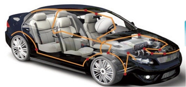
How Wires Carry Signals
Wires are the fundamental pathways for transmitting electrical energy and information in any electromechanical system. Their ability to carry signals efficiently depends on precise physical and electrical properties. For example, a typical 12-volt automotive system uses copper wires with a conductivity of approximately 58×10⁶ S/m, allowing signals to travel at over 90% the speed of light (~270,000 km/s) in ideal conditions. However, real-world factors like wire gauge, insulation material, and environmental interference significantly impact performance. In industrial networks, such as CAN bus or Ethernet protocols, data rates can range from 125 kbps to 100 Mbps, with signal integrity requiring voltage levels maintained within ±0.5 V tolerance. Understanding how wires facilitate this movement of power and data—without significant loss, distortion, or delay—is essential for designing reliable systems.
Electrical signals travel through wires as controlled movements of electrons. The cross-sectional area (CSA) of the wire is a primary factor in its current-carrying capacity. A wire with a 1 mm² CSA can typically safely carry ~10 A of current in open air, but this derates to ~7 A when bundled in a harness due to reduced heat dissipation. For digital signals, such as those in 0-5 V TTL logic, the rise time of a pulse—often as fast as 2-5 nanoseconds—requires careful impedance management to avoid reflection and data errors. Voltage drop over distance is another critical constraint; a 5-meter long 22 AWG wire carrying 2 A may experience a drop of over 0.5 V, which could be unacceptable for sensitive analog sensors requiring ±0.1 V accuracy.
The choice between single-ended signaling (e.g., RS-232) and differential signaling (e.g., RS-485, CAN) is fundamental for noise immunity. Single-ended signals are simpler but susceptible to ground shifts and noise, limiting reliable transmission to typically <15 meters. In contrast, differential pairs cancel out common-mode noise, allowing data to travel over 1,200 meters at 100 kbps with a twist rate of 4-5 twists per centimeter to reject magnetic interference. For high-frequency signals exceeding 1 MHz, characteristic impedance (e.g., 50 Ω, 75 Ω, or 120 Ω for CAN) must be matched to the source and load to prevent standing waves, which can attenuate signal strength by ≥20%.
Shielding is non-negotiable in high-noise environments like factory floors. A braided copper shield with 85% coverage can reduce induced noise by ≥90%, while a foil shield offers 100% coverage for higher-frequency interference above 10 MHz. However, shielding adds ~15-30% to the cost and 20% to the weight of a cable.
|
Signal Type |
Typical Voltage/Current |
Max Reliable Distance |
Data Rate |
Key Constraint |
|---|---|---|---|---|
|
Analog Sensor (4-20 mA) |
4-20 mA loop |
1,000 m |
N/A |
Wire resistance (<10 Ω) |
|
Digital TTL (0-5V) |
0-5 V, ~5 mA |
3 m |
50 Mbps |
Capacitance (<100 pF/m) |
|
CAN Bus |
2.5 V diff. |
40 m (1 Mbps) |
125 kbps - 1 Mbps |
Termination (120 Ω) |
|
Industrial Ethernet |
2.5 V diff. |
100 m |
100 Mbps |
Impedance (100 Ω ±15%) |
Signal integrity degrades with increased capacitance and inductance. A standard 24 AWG twisted pair has a capacitance of ~52 pF/m and an inductance of ~0.6 µH/m. For a 10 MHz signal traveling 20 meters, this can result in a 30% amplitude reduction. Therefore, selecting the right wire type is not just about connectivity—it’s about ensuring that the information arrives intact and on time, with minimal bit error rates (BER) better than 10⁻¹² in critical systems.
Organizing Wires in a System
Effective wire organization is critical for ensuring the reliability, serviceability, and safety of any electromechanical system. A poorly arranged harness can lead to a 40% increase in EMI-related failures and add up to 30% more time to troubleshooting and repairs. In contrast, a well-planned layout minimizes signal interference, reduces mechanical stress, and improves heat dissipation. For example, in a typical industrial control cabinet, over 500 wires might need to be routed through constrained spaces, with clear separation between 120 VAC power lines and low-voltage sensor signals (0-10V) to avoid noise induction. Proper organization also considers future maintenance; systems designed with ≥20% extra length in service loops can reduce rewiring costs by half during upgrades. The goal is to transform a potential maze of cables into a logical, efficient, and durable structure.
The process of organizing wires begins long before physical installation, during the system design and schematic phase. Using ECAD software, engineers define routing paths, bend radii, and separation distances. A fundamental rule is maintaining at least 100 mm of separation between high-power cables (e.g., 20 A motor feeds) and low-voltage communication lines (e.g., EtherCAT or Profinet). This distance reduces induced noise by over 80%. Wires are grouped into sub-harnesses based on function and destination, which simplifies installation—for instance, grouping all 24VDC I/O signals for a robotic arm into one sleeve, reducing clutter and improving airflow.
Strain relief is a mechanical necessity. Fixed anchor points should be placed every 300-400 mm along a harness run to prevent excessive movement, which can cause fatigue failure at termination points after over 50,000 cycles of vibration. Inside moving elements, like a CNC tool changer, wires are organized in continuous-flex tracks with a minimum bend radius of 7.5x the cable diameter to ensure a lifespan exceeding 1 million cycles.
Key materials and methods for organizing wires include:
-
Nylon cable ties: The most common fastener, with a tensile strength ranging from 18 lbs (8 kg) to over 250 lbs (113 kg). They are spaced 150-200 mm apart in a typical harness, but must be carefully tensioned to avoid compressing insulation and degrading wires.
-
Adhesive-backed mounting clamps: These provide secure anchoring to enclosures and can withstand ~50 N of pull-off force per clamp. They are ideal for securing harness branches and preventing dangling wires.
-
Sleeving and conduit: Expandable braided sleeving can increase abrasion resistance by 60%, while corrugated conduit offers superior crush protection, withstanding pressures over 200 N/cm². These protectors also aid in grouping wires and shielding them from oils, coolants, and UV exposure.
-
Wire ducts and channels: Inside control panels, plastic wiring ducts with a ~40% fill capacity are used for neat, accessible routing. This organization cuts fault-finding time by an average of 35% compared to open, tangled wiring.
Organization is not just physical—it's logical. Consistent color-coding (e.g., orange for 120VAC, blue for DC, black for analog signals) and permanent printed labels every 150 mm are indispensable. This practice reduces wiring errors during installation by 25% and slashes mean-time-to-repair (MTTR) by over 50% by allowing technicians to quickly trace circuits. The ultimate aim is to create a system that is not only electrically sound but also mechanically robust and intuitively understandable for the entirety of its 15-20 year operational life.
Protecting Wires from Damage
Wires in electromechanical systems face a constant barrage of threats that can lead to failure: abrasion, heat, chemicals, and vibration. Without robust protection, a single damaged wire can halt an entire production line, with downtime costs averaging $260,000 per hour in automotive manufacturing. Statistics show that over 30% of electrical failures stem from mechanical damage to wiring, not component failure. Protection isn't an optional extra; it's a critical design parameter that directly impacts mean time between failures (MTBF). For instance, a standard PVC-insulated wire abrasion resistance of ~500 cycles can be improved to over 7,000 cycles with the right protective sleeve. Investing in proper protection—often less than 5% of the total harness cost—can prevent the vast majority of these failures, extending system lifespan beyond 10 years even in harsh environments.
Protection starts with selecting the right insulation material for the operating temperature. Standard PVC (Polyvinyl Chloride) is cost-effective for general use with a typical temperature range of -40°C to 105°C. For higher heat areas like near engines or motors, XLPE (Cross-linked Polyethylene) handles up to 150°C, and silicone or Teflon-based insulations can withstand 200°C to 250°C continuously. Using a material rated 20% below its maximum operating temperature significantly extends its life; a wire rated for 150°C operated at 120°C can see its lifespan double from ~20,000 hours to over 40,000 hours.
Mechanical abrasion is a relentless enemy. A wire rubbing against a sharp chassis edge at a frequency of 100 vibrations per minute can wear through its insulation in under 200 hours of operation. This is countered by using protective sleeves. The most common types include:
-
Braided Sleeving (PET/Nylon): Offers good abrasion resistance, increasing wear cycles by ~400%, and provides minor crush protection. It's flexible and adds minimal weight, with a typical temperature resistance of ~125°C.
-
Corrugated Conduit (Polyamide): Provides superior crush protection, withstanding pressures over 200 N/cm², and excellent abrasion resistance. Its segmented design allows for tight bends with a minimum radius of ~4x its diameter.
-
Spiral Wrapping: Ideal for protecting branched harnesses and adding protection after installation. It allows for high flexibility and heat dissipation.
Chemical and environmental exposure requires specific solutions. In wash-down environments or areas exposed to oils and fuels, wires need oil-resistant PVC or halogen-free materials. For UV protection outdoors, materials like black polyethylene with a minimum thickness of 0.5 mm prevent degradation that can reduce insulation resistance from >1000 MΩ to <10 MΩ in under 12 months.
Connecting and Securing Components
The reliability of an entire electromechanical system often hinges on the integrity of its connections. A single poorly secured terminal can lead to voltage drops, heat buildup, and ultimately, system failure. In fact, over 50% of intermittent electrical faults are traced back to faulty connections rather than wire or component failure. The financial impact is significant: a loose high-current connection with just 5 milliohms of excess resistance can dissipate 10 watts of heat when carrying 45 amps, creating a fire risk and pushing local temperatures 70°C above ambient. Conversely, a well-executed connection maintains contact resistance below 0.5 milliohms, ensuring efficient power transfer and a stable voltage profile with less than ±2% deviation. From the choice of connector to the torque on a screw terminal, every detail matters for achieving a service life exceeding 15 years and minimizing unplanned downtime.
Creating a reliable connection starts with the termination method. Crimping is the most common technique, where a metal terminal is compressed onto a wire with a precise force. An optimal crimp deforms the wire to achieve >80% gas-tight compression, preventing oxygen ingress and corrosion. The pull-out strength for a properly crimped 16 AWG wire should exceed 70 lbs (318 N), while the electrical resistance across the crimp must be less than 0.2 milliohms. This requires using the correct tooling; a professional calibrated crimper applies a consistent force within a ±5% variance, while generic pliers can create a weak joint that fails after <100 vibration cycles.
For screw terminals, applying the correct torque is critical. Under-tightening a M4 brass terminal screw below its specified 1.2 N·m can lead to a 40% increase in contact resistance within 500 hours of operation due to relaxation and oxidation. Over-tightening beyond 1.8 N·m can strip the threads or crack the terminal, rendering it useless. Using a calibrated torque screwdriver improves connection consistency by over 90%.
"The difference between a good connection and a great one is often measured in Newton-meters and milliohms."
Once terminated, connectors must be paired and secured. The mating cycle rating—the number of connect-disconnect operations—varies greatly. A standard 0.64 mm pitch PCB header may be rated for 30 cycles, while a circular MIL-SPEC connector can exceed 500 cycles. Key securing methods include:
Testing for Proper Operation
Thorough testing is the final and most critical gatekeeper before a wiring harness is integrated into a system, transforming theoretical design into proven reliability. Skipping rigorous validation can lead to catastrophic failures; a single 50,000+ in downstream damage and production losses. Modern testing protocols go far beyond a simple continuity check. They simulate the harness's entire operational life, subjecting it to temperature cycles from -40°C to 120°C, vibration profiles exceeding 15 Gs of acceleration, and electrical stresses at 150% of its rated voltage. Statistical process control data shows that comprehensive testing catches over 95% of potential failures, such as insulation breaches, high-resistance crimps, and miswires, reducing field failure rates to less than 0.1%. This process is not a cost center but a strategic investment, typically accounting for 10-15% of the total harness manufacturing budget while improving overall product quality by up to 40%.
The foundation of harness testing is Electrical Validation, which begins with a 100% continuity test to verify correct pin-to-pin connections and isolate any opens or shorts. A modern automated test system can check a harness with 120 circuits in under 25 seconds, applying a low current (1-10 mA) and a test voltage of 50-500 VDC to measure resistance. A perfect connection should read < 50 milliohms, while a specification might flag any measurement > 100 milliohms as a potential high-resistance fault. This is followed by Insulation Resistance (IR) testing, where a 500 VDC or 1000 VDC potential is applied between wires and against the shield for 60 seconds. A passing result requires a minimum IR value of > 100 MΩ at 25°C and 50% humidity, ensuring no leakage paths exist. For high-voltage systems in electric vehicles, this test voltage jumps to 2500 VDC to stress the insulation integrity at operating potentials of 400-800 V.
Dielectric Withstanding Voltage (Hi-Pot) testing is a key safety check. It applies a high AC voltage—typically 1500 VAC for 300V-rated systems—for 1 minute between current-carrying conductors and ground. The pass/fail criterion is based on the leakage current not exceeding a threshold, often < 5 mA, with no arcs or breakdowns. This test verifies that the insulation can handle transient voltage spikes 50% above its normal rating.
Beyond the electrical, mechanical and environmental validation is crucial. A vibration test subjects the harness to frequencies from 10 Hz to 2000 Hz for 4-12 hours per axis to simulate years of road or machine vibration, monitoring for any momentary discontinuities longer than 10 microseconds. Thermal cycling between -40°C and 120°C for 50-100 cycles checks that materials expand and contract at similar rates without cracking connectors or breaking seals.
|
Test Type |
Key Parameters |
Pass/Fail Criteria |
Purpose |
|---|---|---|---|
|
Continuity & Resistance |
10 mA @ 10 VDC |
R < 100 mΩ per circuit |
Verifies circuit integrity and connection quality |
|
Insulation Resistance (IR) |
500 VDC, 60 sec |
IR > 100 MΩ |
Checks for insulation leaks or contamination |
|
Hi-Pot (Dielectric) |
1500 VAC, 60 sec |
Leakage < 5 mA, no arc |
Validates insulation strength for safety |
|
Vibration Endurance |
15 G, 10-2000 Hz, 4h/axis |
Zero discontinuities > 10 µs |
Ensures reliability under mechanical stress |
Finally, functional testing under load is the ultimate proof. The harness is connected to its actual controllers and sensors and operated at 100% of its rated current for a 24-hour burn-in period. Temperature sensors monitor terminal blocks for hotspots, with a ΔT rise > 10°C above ambient indicating a high-resistance connection that will fail prematurely. This end-to-end validation, combining low-level electrical checks with high-power functional simulation, ensures the harness will perform reliably for its entire 15-year design life, preventing the vast majority of field failures before they ever occur.
In summary, a wiring harness functions as the central nervous system of an electromechanical assembly, integrating conductors, connectors, and protection components to efficiently transmit power and signals. Properly sized copper wires, with cross-sections from 0.13 mm² to 6 mm², carry currents up to 50 A and data at rates exceeding 100 Mbps, while insulation materials like XLPE withstand temperatures up to 150°C. Organization using sleeves, clamps, and conduits minimizes EMI and abrasion, increasing durability by ≥40%. Secure connections, achieved through precision crimping with <0.5 milliohms resistance, and rigorous testing—including 1000 VDC hipot and continuity checks—ensure reliability, reducing field failure rates to <0.1% and supporting system lifespans beyond 10 years.
