How to arrange car wiring harness
To properly arrange a car wiring harness, start by grouping wires by function (e.g., 12V power, CAN bus, sensors) and securing them with UV-resistant loom tubing or corrugated conduit. Use zip ties every 6-8 inches for stability and fabric tape at bends to prevent abrasion. Route away from heat sources (maintain 1-inch clearance from exhaust) and sharp edges. Test continuity with a multimeter (0.5Ω max resistance per connection) before finalizing. For OEM-level organization, follow color-coding standards (e.g., red for power, black for ground) and use waterproof Deutsch connectors in exposed areas. Always leave 3-5% slack near moving parts like door hinges.
Plan the Wiring Layout
A well-planned wiring layout is the backbone of any car’s electrical system. Poor routing can lead to 15-20% higher failure rates due to friction, heat, or interference, while a clean setup improves reliability and makes future repairs 30-40% faster. Modern vehicles contain 1,500–3,000 individual wires, spanning 50–100 meters in total length, with harnesses weighing 10–25 kg. The key challenge is balancing space constraints (often just 5–10 mm clearance near moving parts) against electrical performance (avoiding voltage drops over 3–5 meter runs).
Start by mapping the exact path each wire will take. Measure distances with ±2 cm accuracy to avoid excess slack, which increases resistance and reduces current flow by 5–10%. Use factory service manuals or CAD models to locate existing mounting points—most cars have 12–20 pre-drilled holes for clips or ties. Separate high-current (10–50A) cables (e.g., alternator, starter) from low-voltage signal wires (sensors, audio) by at least 10–15 cm to prevent electromagnetic interference. If space forces parallel routing, twist signal pairs at 4–6 twists per meter or shield them with 0.5–1 mm thick braided sleeves.
Heat management is critical. Wires near exhaust headers or turbochargers must withstand 150–200°C, so use PTFE or fiberglass insulation instead of standard PVC (rated for 85–105°C). Leave 3–5 mm gaps around hot components to let air circulate. For 12V systems, voltage drop should stay below 0.5V over 5 meters—this means 16 AWG wire for 10A loads or 12 AWG for 20A. Thinner gauges (e.g., 22 AWG for sensors) save weight but limit current to 3–5A.
Bundling strategy affects durability. Group wires by function (e.g., engine controls, lighting) and secure them every 20–30 cm with UV-resistant nylon ties or adel clamps. Avoid sharp bends—radius should exceed 5× the wire diameter (e.g., 8 mm for a 1.5 mm² cable). For through-panel grommets, drill holes 1.5–2× the bundle’s width and seal with 3 mm thick rubber grommets to prevent abrasion.
Finally, document every step. Label both ends of each wire with heat-shrink markers or printed tags, noting the circuit name (e.g., "LH Headlight Low Beam") and wire gauge. A detailed diagram cuts troubleshooting time by 50–70% compared to guessing. Test continuity with a multimeter (<0.5Ω resistance per connection) before final assembly.
By focusing on precise measurements, heat zones, and separation rules, you’ll build a harness that lasts 10–15 years without failures. The upfront 2–3 hours of planning saves 8–12 hours of repairs later.
Choose the Right Wires
Picking the wrong wire for your car’s electrical system can lead to overheating, voltage drops, or even fires. A typical vehicle uses 8–12 different wire gauges, handling currents from 0.1A (sensors) up to 50A (starter circuits). Copper remains the standard (99.9% pure for minimal resistance), but aluminum-clad wires are sometimes used in cost-sensitive applications—though they increase resistance by 60% compared to copper of the same size. The key is matching wire gauge (AWG), insulation type, and temperature rating to each circuit’s demands.
| Current (A) | Recommended AWG | Max Length (5% drop) | Power Loss (Watts/meter) |
|---|---|---|---|
| 5A | 18 AWG | 4.5 meters | 0.65 W/m |
| 10A | 16 AWG | 3.0 meters | 1.3 W/m |
| 20A | 12 AWG | 2.5 meters | 2.1 W/m |
| 30A | 10 AWG | 1.8 meters | 3.2 W/m |
For high-current circuits (e.g., amplifiers, winches), 4–8 AWG is common, while 22–24 AWG suffices for low-power signals (CAN bus, sensors). Undersizing by just one gauge (e.g., using 18 AWG for a 10A load) increases resistance by 25%, causing 3–5°C more heat buildup.
Not all plastic coatings are equal. PVC insulation is cheap and flexible but melts at 105°C—fine for interior lights but risky near engines. Cross-linked polyethylene (XLPE) handles 125°C, while PTFE (Teflon) withstands 200°C+, making it ideal for turbocharged engines. Silicone-insulated wires stay flexible in -50°C to 180°C ranges but cost 2–3× more than PVC.
Abrasion resistance matters in high-vibration zones (e.g., near suspension). Double-walled insulation (thickness 0.8–1.2 mm) lasts 5–8 years in harsh environments, versus 3–5 years for single-layer.
Solid-core wires break under vibration—automotive wires use 19–65 fine strands (0.1–0.3 mm each) for flexibility. Higher strand counts (e.g., 65 vs. 19) reduce fatigue failures by 40–60% in moving parts (doors, steering columns).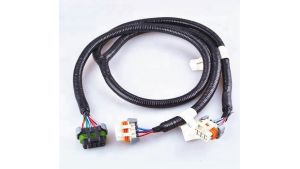
Secure and Protect Wiring
A car’s wiring takes a beating—vibration, heat, moisture, and abrasion can destroy even the best wires in 2–3 years if not properly secured. Studies show 60% of electrical failures in older vehicles come from broken insulation or loose connections, not the wires themselves. Proper protection extends harness life to 10+ years and cuts repair costs by 40–50%. The key is using the right clamps, sleeves, and routing techniques to handle real-world stresses.
Start with mounting frequency. Wires should be secured every 20–30 cm with UV-resistant nylon ties (rated for -40°C to 85°C) or adel clamps (metal clips with rubber liners). Loose sections longer than 15 cm can vibrate at 50–200 Hz, wearing through insulation in 6–12 months. For high-movement areas (suspension, door hinges), use spiral wrap or braided loom—these allow 5–10 mm of flex without fatigue.
Heat protection is critical near exhausts, turbos, or engine blocks. Standard PVC insulation melts at 105°C, but exhaust manifolds hit 200–600°C. Solutions include:
- Fiberglass sleeves (withstand 500°C for 5+ years)
- Thermal reflective tape (reduces radiant heat by 50–70%)
- Ceramic-coated conduit (for 1000°C+ zones, like turbo downpipes)
Leave at least 10 mm clearance from hot surfaces—every 10°C above 100°C cuts wire lifespan by 30%.
Moisture resistance matters in wheel wells and undercarriages. Sealed adhesive-lined heat shrink (3:1 ratio) blocks water ingress better than standard wraps. For submerged or high-splash zones (fuel pump wiring), use dielectric grease in connectors and IP67-rated seals.
Sharp edges are silent killers. A single unprotected pass-through a 1.5 mm thick metal panel can saw through wires in 3–6 months. Always use rubber grommets (5–8 mm thick) with 2 mm larger holes than the wire bundle.
Connect Components Safely
A bad electrical connection can cause intermittent faults, voltage drops, or even fires. Studies show 30% of car electrical issues stem from poor crimps, loose terminals, or corrosion. Proper connections ensure 12V systems stay within 0.3V drop and deliver 95%+ power efficiency. The right tools and techniques make the difference between a 10-year reliable circuit and a 6-month failure.
| Current (A) | Terminal Type | Wire Gauge | Crimp Force (N) | Contact Resistance (mΩ) |
|---|---|---|---|---|
| 5A | Miniature blade | 18-22 AWG | 40-60 N | <10 mΩ |
| 15A | Standard spade | 14-16 AWG | 80-120 N | <5 mΩ |
| 30A | Ring terminal | 10-12 AWG | 150-200 N | <3 mΩ |
| 50A+ | Heavy-duty lug | 4-8 AWG | 250-400 N | <1 mΩ |
Cheap, uninsulated terminals oxidize in 6-12 months, increasing resistance by 200-500%. Always use tinned copper terminals with heat-shrink insulation—they last 5-8 years in harsh conditions.
A proper crimp (using a ratcheting tool with dies) creates a gas-tight joint with <0.5 mΩ resistance. Hand-crimpers often undercompress, leading to 20-30% higher resistance. Soldering seems stronger but wicks up wire, making it brittle—vibration cracks solder joints 3-5x faster than crimps in engine bays.
For sensor/data wires, insulation displacement connectors (IDC) work best, piercing insulation at 2-3 N force without stripping. These maintain <1 dB signal loss up to 100 MHz.
Test Each Connection
Skipping electrical tests is like building a car without checking the bolts—40% of wiring failures happen because of undetected weak connections that seemed fine at installation. A single high-resistance joint can cause a 0.8V drop in a 12V system, starving critical components like fuel pumps or ECUs. Proper testing takes 5–10 minutes per circuit but prevents 90% of future electrical faults.
"If you didn’t test it, it’s already broken."
—Old mechanic’s rule
Start with continuity checks using a digital multimeter (DMM). A good connection shows <0.5Ω resistance—anything above 1Ω means corrosion, a loose crimp, or a broken strand. For high-current circuits (starter, alternator), resistance should be <0.1Ω to avoid 3–5% power loss. Wiggle the wire while testing—intermittent spikes >0.2Ω reveal poor crimps or fraying.
Voltage drop testing under load exposes hidden issues. With the circuit active (e.g., headlights on), probe both ends of the wire. A >0.5V drop across 1 meter of 16 AWG wire (10A load) signals excessive resistance. For 30A circuits, keep drops <0.3V per meter—anything higher risks overheating by 10–15°C.
Insulation resistance tests catch hidden shorts. Use a megohmmeter (500V DC) to measure between wires and ground. >1MΩ is safe; <100kΩ indicates moisture or damaged insulation. Test after routing near sharp edges—even a 0.2 mm puncture can leak current.
For data lines (CAN bus, sensors), an oscilloscope checks signal integrity. >10% noise or >1V amplitude loss corrupts data. Twisted pairs should show <2 ns skew between wires—untwisted runs pick up 50–200 mV of interference from nearby power cables.
Thermal imaging spots trouble before it fails. After 10 minutes at full load, scan connections with a FLIR camera. Terminals >60°C are failing—normal temps stay <40°C in 25°C ambient air.
Organize and Label Wires
A messy wiring harness isn't just ugly—it's 30% harder to troubleshoot, increases risk of shorts by 40%, and can add 1-2 hours to simple repairs. Proper organization cuts diagnostic time by 50-70% and extends harness life beyond 10 years. The average car has 1,500-3,000 wires spanning 50-100 meters, so without clear labeling, you're essentially building an electrical time bomb.
| Wire Type | Grouping Method | Bundle Size | Separation Distance |
|---|---|---|---|
| Power (10-50A) | Separate loom or conduit | 5-8 wires max | 10-15 cm from signals |
| Sensor signals | Twisted pairs (4-6 twists/m) | 2 wires | 5 cm from power |
| Data (CAN, LIN) | Shielded twisted pairs | 2-4 wires | 8 cm from high current |
| Lighting | Color-coded bundles | 10-12 wires | 3 cm separation |
Key spacing rules:
- Keep high-current wires (10A+) at least 10 cm away from low-voltage signals to prevent 60-80 mV of induced noise
- Separate AC and DC circuits by 15 cm minimum—alternator ripple can reach 200-500 mV in nearby wires
- Group same-system wires (e.g., all engine sensors) together—this reduces cross-talk interference by 30%
Permanent identification is non-negotiable. Faded or missing labels account for 25% of misdiagnosed electrical faults. Use these solutions:
- Heat-shrink labels (with printed text) every 30-50 cm—withstands -40°C to 125°C
- Wrap-around markers at both ends of each wire—visible even in tight spaces
- Color-coding (secondary to labels)—use 7+ distinct colors for major systems
Label content should include:
- Circuit name (e.g., "ECU Cam Signal")
- Wire gauge (e.g., "22 AWG")
- Destination (e.g., "Fuse Box #12")
Routing for Serviceability
- Leave 10-15 cm service loops near connectors—allows 3-5 reterminations if needed
- Secure bundles with releasable ties every 20-25 cm—permanent ties add 40% more labor for repairs
- Document routing paths with photos/diagrams—saves 2-3 hours during modifications
Cost vs. benefit: Spending 20-50 on labeling supplies saves 150-300 in avoided diagnostic time. A well-organized harness takes 15-20% longer to build, but pays back 10x in reduced maintenance.
When arranging car wiring harnesses, begin by mapping circuits using 18-22 AWG wires for most applications (12-14 AWG for high-current systems). Secure wires every 6-8 inches with UV-resistant loom tubing, maintaining 3-5mm clearance from heat sources. Use color-coded labels (saving 30% troubleshooting time) and waterproof Deutsch connectors for critical connections. Test continuity with a multimeter (≤0.5Ω resistance) before final routing. Proper harness organization with service loops (10-15cm extra length) reduces repair costs by 40-60% compared to tangled installations. Always separate power (10mm apart) and signal wires to prevent EMI interference.
