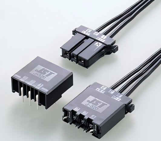
JST JFA Connector J320M Series, Custom Wire Assembly
JST JFA Connector
The JST JFA Connector series is designed to meet the demands of signal and power supply circuits in industrial applications such as factory automation, heavy electrical machinery, and other general industrial equipment. This connector line offers a versatile range of housing options, yet features a standardized contact design to ensure compatibility and simplicity. The use of standardized tooling further enhances its practicality, reducing complexity and costs in assembly. Key features include a reliable double-spring construction for secure contact retention, housing lances for added stability, and a clear tactile click for a confident mating experience. This combination of features ensures robust performance and ease of use across diverse industrial settings.
JFA 320M Series
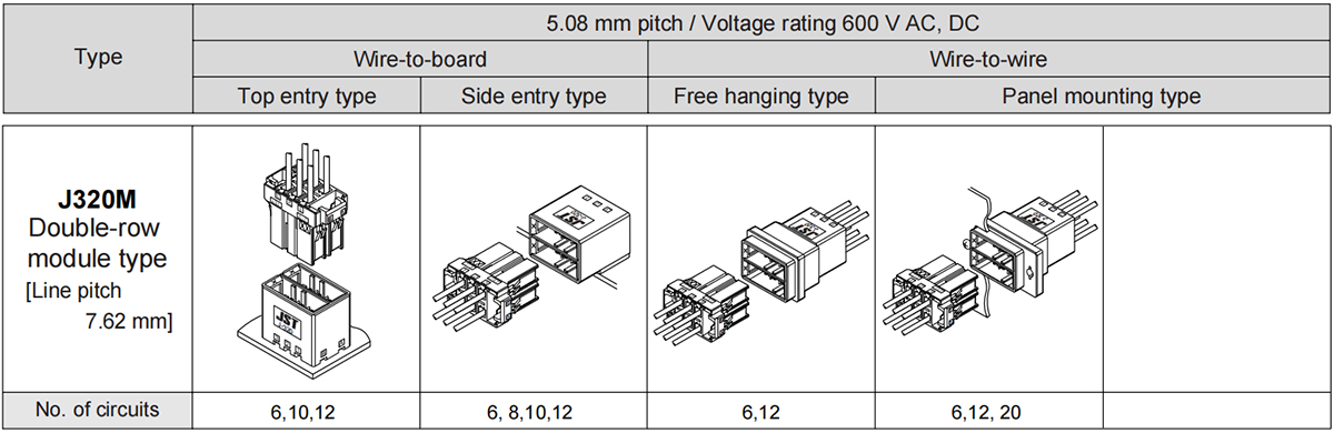
Specifications
- Connector type: Wire to Board, Wire to Wire, Disconnectable Crimp style
- Connector pitch: 5.08mm
- Voltage rating: 600 V AC, DC
- Temperature range: -55°C to +105°C (including temperature rise in applying electrical current)
- Contact resistance: Initial value/ 5 mΩ max, After environmental tests/ 10 mΩ max.
- Insulation resistance: 1,000 MΩ min.
- Withstanding voltage: 2,200 VAC/minute
- Applicable wire: AWG #28 to #14
- Applicable PC board thickness: 1.6 to 2.4 mm
J320M Receptacle Housing
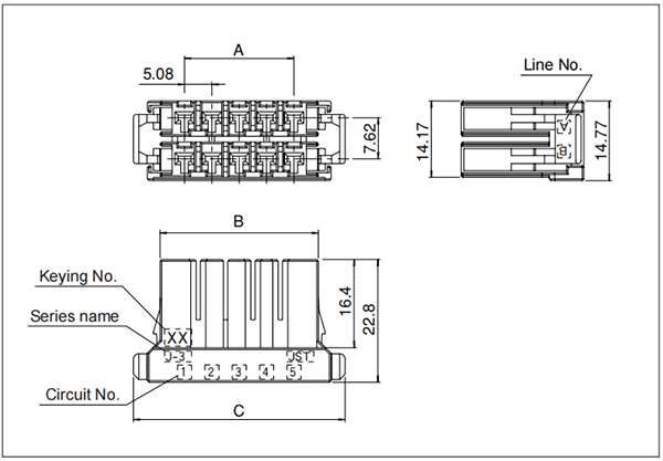
| Circuits | Keying | Model No. | Dimensions (mm) | Q'ty/bag | ||
| A | B | C | ||||
| 6 | XX | F32FMS-06V-KXX | 10.16 | 19.24 | 29.16 | 100 |
| YY | F32FMS-06V-KYY | 10.16 | 19.24 | 29.16 | 100 | |
| XY | F32FMS-06V-KXY | 10.16 | 19.24 | 29.16 | 100 | |
| 10 | XX | F32FMS-10V-KXX | 20.32 | 29.4 | 39.32 | 100 |
| YY | F32FMS-10V-KYY | 20.32 | 29.4 | 39.32 | 100 | |
| XY | F32FMS-10V-KXY | 20.32 | 29.4 | 39.32 | 100 | |
| 12 | XX | F32FMS-12V-KXX | 25.4 | 34.48 | 44.4 | 100 |
| YY | F32FMS-12V-KYY | 25.4 | 34.48 | 44.4 | 100 | |
| XY | F32FMS-12V-KXY | 25.4 | 34.48 | 44.4 | 100 | |
| 20 | XX | F32FMS-20V-KXX | 45.72 | 54.8 | 64.72 | 84(box) |
Material and Finish: Glass-filled PBT, UL94V-0, black
Tab housing (Free hanging type)
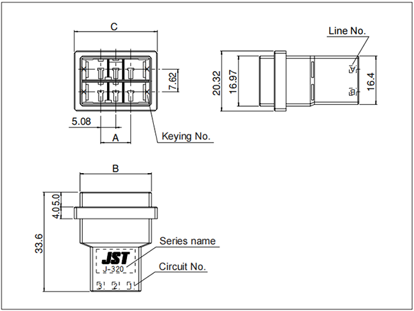
| Circuits | Keying | Model No. | Dimensions (mm) | Q'ty/bag | ||
| A | B | C | ||||
| 6 | XX | F32MDF-06V-KXX | 10.16 | 24.16 | 28.11 | 100 |
| YY | F32MDF-06V-KYY | 10.16 | 24.16 | 28.11 | 100 | |
| XY | F32MDF-06V-KXY | 10.16 | 24.16 | 28.11 | 100 | |
| 12 | XX | F32MDF-12V-KXX | 25.4 | 39.4 | 43.35 | 100 |
| YY | F32MDF-12V-KYY | 25.4 | 39.4 | 43.35 | 100 | |
| XY | F32MDF-12V-KXY | 25.4 | 39.4 | 43.35 | 100 | |
Material and Finish: Glass-filled PBT, UL94V-0, black
Tab housing (Panel mounting type)
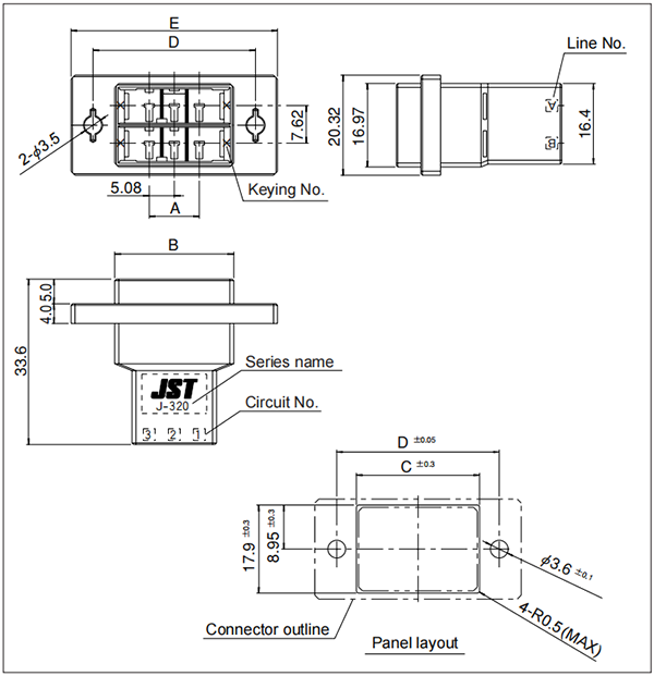
| Circuits | Keying | Model No. | Dimensions (mm) | Q'ty/bag | ||||
| A | B | C | D | E | ||||
| 6 | XX | F32MDP-06V-KXX | 10.16 | 24.16 | 25 | 33 | 41.91 | 100 |
| YY | F32MDP-06V-KYY | 10.16 | 24.16 | 25 | 33 | 41.91 | 100 | |
| XY | F32MDP-06V-KXY | 10.16 | 24.16 | 25 | 33 | 41.91 | 100 | |
| 12 | XX | F32MDP-12V-KXX | 25.4 | 39.4 | 41 | 49 | 57.91 | 100 |
| YY | F32MDP-12V-KYY | 25.4 | 39.4 | 41 | 49 | 57.91 | 100 | |
| XY | F32MDP-12V-KXY | 25.4 | 39.4 | 41 | 49 | 57.91 | 100 | |
| 20 | XX | F32MDP-20V-KXX | 45.72 | 59.72 | 61 | 70 | 78.23 | 42(box) |
Note:
- Material and inishGlass-filled PBT, UL94V-0, black
- Punch holes in the panel. Burrs must be removed.
- The strength of the panel must be considered when punching two or more holes.
- The connector must be inserted from the same side as the hole is punched.
- RoHS2 compliance
Terminal
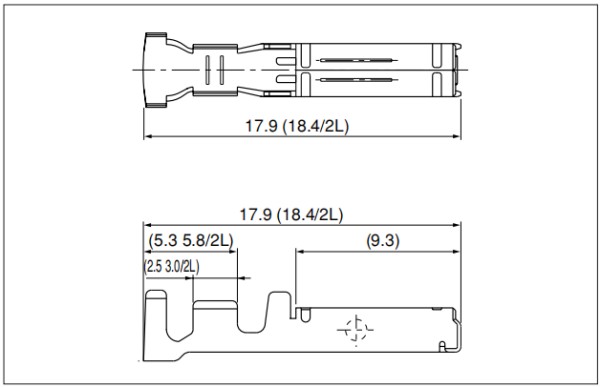
Receptacle contact
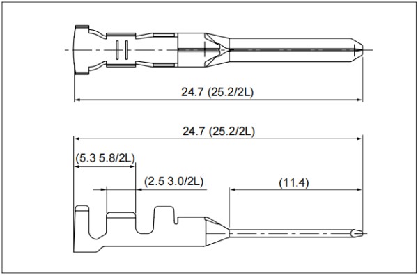
Tab contact
| Terminal Type | Model No. | Applicable wire | Insulation 0.D (mm) |
Q'ty | ||||
| Strip contact | Loose piece | Size | mm² | AWG# | reel | box(Loose piece) | ||
| Receptacle | SF3F-002(*)-P2.0 | BF3F-002(*)-P2.0 | S | 0.08~0.20 | 28~24 | 0.8~1.4 | 3700 | 1000 |
| SF3F-01(*)-P2.0 | BF3F-01(*)-P2.0 | M | 0.20~0.50 | 24~20 | 1.2~2.6 | 3700 | 1000 | |
| SF3F-41(*)-P2.0 | LF3F-41(*)-P2.0 | L | 0.50~1.25 | 20~16 | 1.8~2.8 | 3200 | 1000 | |
| SF3F-71(*)-P2.0 | BF3F-71(*)-P2.0 | 2L | 1.25~2.0 | 16~14 | 2.4~3.4 | 3200 | 1000 | |
| Tab | SF3M-002(*)-M2.0N | BF3M-002(*)-M2.0N | S | 0.08~0.20 | 28~24 | 0.8~1.4 | 3500 | 1000 |
| SF3M-01(*)-M2.0N | BF3M-01(*)-M2.0N | M | 0.20~0.50 | 24~20 | 1.2~2.6 | 3500 | 1000 | |
| SF3M-41(*)-M2.0N | LF3M-41(*)-M2.0N | L | 0.50~1.25 | 20~16 | 1.8~2.8 | 3300 | 1000 | |
| SF3M-71(*)-M2.0N | BF3M-71(*)-M2.0N | 2L | 1.25~2.0 | 16~14 | 2.4~3.4 | 3200 | 1000 | |
Notes:
- Material and Finish: Copper alloy (superior conductivity), nickel-undercoated, selective gold-plated, tin-plated (reflow treatment)
- Finish (*):
- GF...Nickel-undercoated, 0.38μm selective gold-plated
- GI....Nickel-undercoated, 0.76μm selective gold-plated
- T......Tin-plated (reflow treatment)
Header (Top entry type)
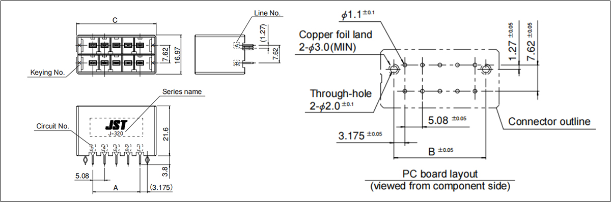
| Circuits | Keying | Model No. | Dimensions (mm) | Q'ty/box | ||
| A | B | C | ||||
| 6 | XX | B06B-F32MK-GGXXR | 10.16 | 16.51 | 24.16 | 120 |
| YY | B06B-F32MK-GGYYR | 10.16 | 16.51 | 24.16 | 120 | |
| XY | B06B-F32MK-GGXYR | 10.16 | 16.51 | 24.16 | 120 | |
| 10 | XX | B10B-F32MK-GGXXR | 20.32 | 26.67 | 34.32 | 84 |
| YY | B10B-F32MK-GGYYR | 20.32 | 26.67 | 34.32 | 84 | |
| XY | B10B-F32MK-GGXYR | 20.32 | 26.67 | 34.32 | 84 | |
| 12 | XX | B12B-F32MK-GGXXR | 25.40 | 31.75 | 39.40 | 72 |
| YY | B12B-F32MK-GGYYR | 25.40 | 31.75 | 39.40 | 72 | |
| XY | B12B-F32MK-GGXYR | 25.40 | 31.75 | 39.40 | 72 | |
Material and Finish
- Tab contact: Copper alloy, nickel-undercoated, selective gold-plated
- Housing: Glass-filled PBT, UL94V-0, black
- Reinforcement: Copper alloy, nickel-undercoated, selective gold-plated
Header (Side entry type)
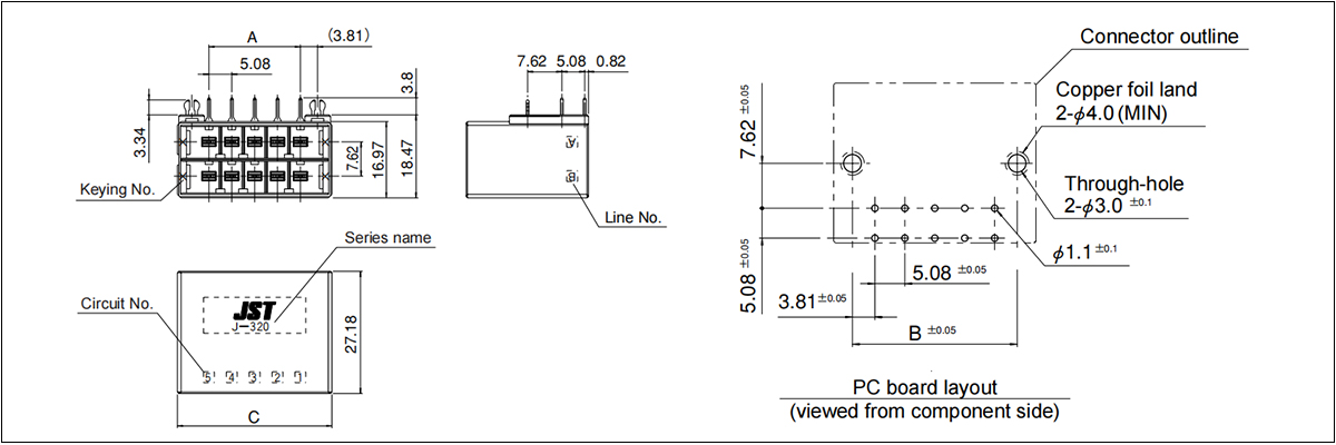
| Circuits | Keying | Model No. | Dimensions (mm) | Q'ty/box | ||
| A | B | C | ||||
| 6 | XX | S06B-F32MK-GGXXR | 10.16 | 17.78 | 24.16 | 80 |
| YY | S06B-F32MK-GGYYR | 10.16 | 17.78 | 24.16 | 80 | |
| XY | S06B-F32MK-GGXYR | 10.16 | 17.78 | 24.16 | 80 | |
| 8 | XY | S08B-F32MK-GGXYR | 15.24 | 22.86 | 29.24 | 64 |
| 10 | XX | S10B-F32MK-GGXXR | 20.32 | 27.94 | 34.32 | 56 |
| YY | S10B-F32MK-GGYYR | 20.32 | 27.94 | 34.32 | 56 | |
| XY | S10B-F32MK-GGXYR | 20.32 | 27.94 | 34.32 | 56 | |
| 12 | XX | S12B-F32MK-GGXXR | 25.40 | 33.02 | 39.40 | 48 |
| YY | S12B-F32MK-GGYYR | 25.40 | 33.02 | 39.40 | 48 | |
| XY | S12B-F32MK-GGXYR | 25.40 | 33.02 | 39.40 | 48 | |
Material and Finish
- Tab contact: Copper alloy, nickel-undercoated, selective gold-plated
- Housing: Glass-filled PBT, UL94V-0, black
- Reinforcement: Copper alloy, nickel-undercoated, selective gold-plated
Support Custom Wiring Harness Assembly
- Connector: 6, 10, 12, 20pin
- Wire gauge: 14 - 28AWG
- Wire length: as long as your needs
- Wire color: white, black, red, yellow, grey, blue, green, purple, orange, brown, etc.
- Custom type:
- wire to wire
- wire to tinned end
- wire to open end
- wire to any suitable connectors
- Minimum Order: 100 pieces per order.
Customize Your Wire Harness
Send us your sample or drawing/schematic for quote price→ Feedback with quotation(1~3 days) → Confirm quotation → Arrange sample you for approval→ [Make mold if needed (7 days) →Mold test] → Making samples(1~3 days)→Samples test(Approval) → place order for Mass production(2~3 weeks)→ Quality checking→ Packing → Delivery → After Service → Repeat Order.
