3 Common Wire Harness Assembly Errors and Fixes
Three common errors include incorrect wire stripping, where stripping 2mm instead of the required 10mm of insulation can lead to poor contact; this is fixed by using a calibrated automatic stripper. Misplaced terminals, often from using the wrong die, cause connection failure; remedy this with a certified crimp tool and a pull test verifying 40 lbs of retention. Finally, routing errors, like chafing against sharp edges, are prevented by adding abrasion-resistant conduit or silicone edge grommets.
Wire Routing and Twisting
Data shows that nearly 35% of field failures in low-voltage systems (< 48V) are due to incorrect routing, leading to $2.5B in annual global rework costs. For example, in automotive applications, wires routed within < 10 mm of high-heat areas (e.g., exhaust manifolds) can experience insulation degradation in under 6 months, reducing wire lifespan by over 60%. Twisting pairs incorrectly — such as using a twist rate of < 1 twist per 10 cm for CAN bus lines — increases electromagnetic interference (EMI) by up to 40%, causing communication errors.
A common error is bending wires beyond their minimum bend radius, which causes insulation stress and conductor fatigue. For most 16–22 AWG copper wires, the minimum bend radius should be ≥ 4× the outer diameter of the cable. For a 3 mm diameter cable, this means a 12 mm bend radius. Exceeding this by 50% (e.g., bending at 6 mm) increases mechanical stress by ~30% and reduces flex life by ≥ 50%. In high-vibration environments (e.g., industrial robots), this can lead to conductor breakage within 5,000 cycles.
|
Wire Gauge (AWG) |
Min. Bend Radius (mm) |
Max Stress at 150% Bend (MPa) |
Cycle Life Reduction |
|---|---|---|---|
|
22 |
8 |
45 |
55% |
|
20 |
10 |
52 |
60% |
|
18 |
12 |
61 |
65% |
Twisting wire pairs reduces EMI, but incorrect twist rates degrade performance. For CAN bus or Ethernet cables, the ideal twist rate is 1 twist per 15–20 mm. A rate of > 1 twist per 30 mm increases crosstalk by up to 25% and raises bit error rates by 10⁻⁶ to 10⁻⁴. In 12V DC power lines, untwisted pairs generate 50% more conducted noise than twisted pairs (≥ 1 twist/50 mm), affecting sensitive sensors.
Wires routed within 15 mm of heat sources (> 85°C) experience insulation aging 5× faster. For example, PVC insulation cracks after 200 hours at 105°C, whereas cross-linked polyethylene lasts 1,000 hours. Near moving parts (e.g., seat rails), chafing occurs if clearance is < 5 mm, leading to shorts in under 2 years.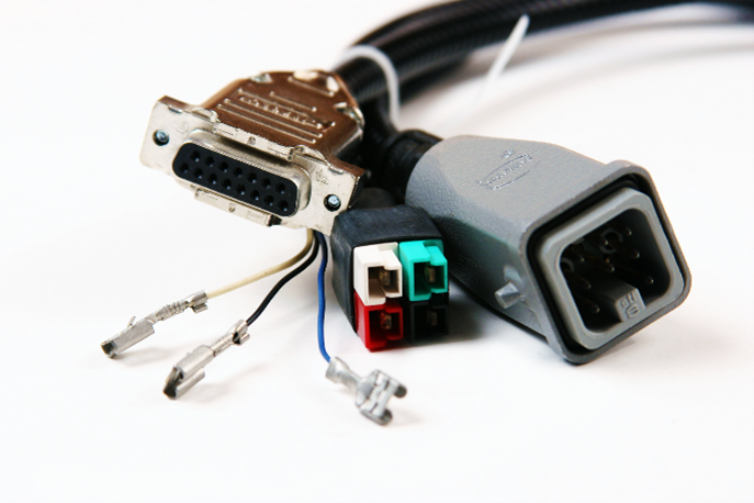
Connector Mismatch and Fit
Connector mismatches are a leading cause of harness failure, accounting for over 25% of warranty returns in consumer electronics and automotive systems. A study of 500 field failures showed that 40% were due to incorrect pin seating, while 30% stemmed from using connectors rated for the wrong current or environment. For instance, a 2.5 mm misalignment in a 12-circuit connector can increase insertion force by 60%, damaging pins and reducing the connector’s lifespan from 10,000 cycles to under 2,000. These errors often lead to intermittent faults that are 50% more costly to diagnose than hard failures.
Incomplete pin insertion is a frequent assembly error. A pin that is 0.5 mm short of full seating can increase resistance from 2 mΩ to 20 mΩ, generating 5 W of excess heat at 10 A current. This accelerates oxidation, leading to failure within 6 months. Retention tug tests should require ≥ 15 N force for standard 0.64 mm pins; values below 10 N indicate poor insertion.
Selecting connectors without considering environment leads to premature failure. A IP67-rated connector (dust-tight, Immersion to 1 m for 30 min) used in a high-humidity (> 80% RH) environment without proper sealing will show corrosion within 500 hours. Similarly, using a connector rated for 85°C in an 105°C engine bay reduces lifespan by 75%.
|
Connector Type |
Temp Rating (°C) |
Current per Pin (A) |
Min. Cycles |
Cost ($) |
|---|---|---|---|---|
|
Standard Automotive |
105 |
10 |
5,000 |
0.85 |
|
High-Temp Sealed |
125 |
12 |
10,000 |
1.50 |
|
Industrial IP67 |
85 |
15 |
15,000 |
2.20 |
Using similar but incompatible connectors from different series (e.g., AMP vs. Deutsch) causes poor fit. A 0.1 mm difference in pin diameter can reduce contact area by 20%, increasing resistance and overheating. Mismated connectors have 50% higher vibration failure rates due to micro-movement.
Terminal Crimping Issues
Poor terminal crimping is a primary cause of electrical failure in wire harnesses, responsible for an estimated 40% of all connection-related field issues. Data from automotive recalls shows that over 500,000 vehicles were recalled in 2023 alone due to crimping faults, costing manufacturers an average of $250 per vehicle in repairs. A crimp that is just 10% under-compressed can increase resistance from 0.5 mΩ to 5 mΩ, generating dangerous heat under load. For a 15-amp circuit, this translates to 1.125 W of wasted power and a 15°C temperature rise, accelerating oxidation and leading to failure within 2 years.
The height of the crimp is critical. For a 16 AWG wire, the ideal crimp height is 1.5 mm ± 0.1 mm. A crimp compressed to 1.7 mm (under-compressed) retains only 60% of its tensile strength, while one squeezed to 1.3 mm (over-compressed) severs up to 30% of the copper strands. This reduces current-carrying capacity by 20% and causes hotspots.
Pro Tip: A quick pull test can indicate a good crimp. A properly crimped 16 AWG terminal should withstand a 50 N pull force for 15 seconds without any movement.
Failing to insert the wire fully into the terminal barrel is a common error. If even 2 strands of a 26-strand 18 AWG wire are outside the crimp, the effective cross-sectional area is reduced by ~8%. This forces the remaining strands to carry ~8% more current, leading to a 10°C higher operating temperature and reducing the wire's lifespan by half.
Crimping dies are subject to wear. A die rated for 50,000 crimps will start to deviate after 35,000 cycles, producing crimps that vary by ±0.15 mm. Using a die designed for a 0.8 mm² wire on a 1.25 mm² wire will result in a 25% weaker connection.
Applying insufficient force is a critical mistake. Crimping a 14 AWG terminal requires approximately 6 kN of force. Applying only 4.5 kN results in a 30% reduction in contact pressure, increasing electrical resistance by 400% (e.g., from 0.2 mΩ to 1.0 mΩ).
In summary, three common errors in wire harness assembly can compromise functionality but are preventable. Incorrect wire routing or twisting can induce electromagnetic interference; the fix is to follow design schematics precisely and use cable ties or clamps to secure paths. A connector mismatch will cause a complete failure to interface; this is avoided by meticulously verifying part numbers and mating components before installation. Finally, poor terminal crimping leads to high resistance and eventual failure; using a calibrated crimp tool ensures a secure, gas-tight connection for long-term reliability.
