5 Common Wire Harness Problems & How to Fix Them
loose terminals (re-crimp to ≥50N pull test), cracked insulation (swap to XLPE, 125°C-rated), overloading (upgrade to 0.75mm² wire, 18A capacity), shorts (seal with IP67 gel), vibration loosening (torque M12 connectors to 8N·m).
Loose Connector Fix
Industry studies show that up to 50% of all electrical faults in automotive and industrial equipment originate from poor connector contact. A connector with even 0.5 mm of excess play can cause intermittent signals, voltage drops exceeding 2 volts, and eventual connection failure. In high-vibration environments—like automotive engines or industrial machinery—a poorly secured connector can fully disconnect in under 90 seconds under typical operating conditions. These failures aren’t just inconvenient; they lead to unplanned downtime, with repair costs averaging 500 per incident when diagnosed by a professional. The good news is that most loose connector issues can be identified and resolved in under 15 minutes with basic tools, preventing longer-term damage to circuits and components.
Gently wiggle each connector while the system is operating—if you notice flickering lights, intermittent operation, or a sudden voltage drop below 0.5V at the connector pins, you’ve likely found the issue. For a more precise check, use a digital multimeter to measure resistance across the connector. A good connection should read under 0.1 ohms; anything above 0.5 ohms indicates a loose or corroded terminal that needs attention. Once you’ve located the loose connector, power down the system completely to avoid short circuits. Most connectors use a locking tab or latch—ensure it’s fully engaged. If it’s broken, replace the connector housing, which typically costs 8 and takes 5 minutes to swap.
For threaded or screw-type connectors—common in battery and high-power applications—use a torque screwdriver and tighten to the manufacturer’s specification, usually between 0.6 N·m and 2.5 N·m. Overtightening can strip threads or crack plastic housings, so follow the spec closely. After reseating or replacing, retest the connection. Resistance should return to under 0.1 ohms, and voltage drop at the connector should be less than 0.2V under load. Applying a thin layer of dielectric grease to the terminals can help prevent future corrosion and maintain stable contact, especially in environments with high humidity or temperature swings between -40°C and 120°C. For critical systems, consider adding a strain relief clip or cable tie within 50 mm of the connector to reduce mechanical stress on the connection point during movement or vibration. This simple addition can extend the connector’s service life by up to 3 years.
Repairing Worn Wire Cover
Studies indicate that up to 30% of electrical failures in automotive and industrial applications stem from degraded wire covering. When insulation wears through just 0.2 mm of its thickness, the risk of a short circuit increases by over 60%. In high-temperature environments (above 85°C), standard PVC insulation can become brittle and crack within 2–3 years, while in high-abrasion zones, constant rubbing can wear through a 1.5 mm thick wall in under 12 months. The cost of ignoring a worn section is high: a full wire harness replacement can run between 1,200, not including the 2–3 hours of labor at
| Material Type | Typical Thickness | Max Temp Rating | Min Bend Radius | Abrasion Resistance | Cost per Meter |
|---|---|---|---|---|---|
| PVC | 0.8 mm - 1.2 mm | 105°C | 4x Diameter | Low | 1.00 |
| Cross-Linked Polyethylene | 1.0 mm - 1.5 mm | 125°C | 3x Diameter | Medium | 2.50 |
| Silicone Rubber | 1.2 mm - 2.0 mm | 200°C | 2x Diameter | Low | 6.00 |
| Abrasion-Resistant Nylon | 0.5 mm - 1.0 mm | 125°C | 5x Diameter | High | 4.00 |
| Heat-Shrink Tubing | 0.8 mm - 1.5 mm | 135°C | N/A | Medium | 3.00 |
Gently bend the wire; if the insulation cracks audibly at a 180-degree bend, it has lost its plasticity and must be repaired. For minor abrasions where less than 50% of the insulation thickness is worn, a simple wrap of 3M Scotch 35+ electrical tape can be a temporary fix. Wrap the tape with a 50% overlap for a minimum of three layers, extending at least 40 mm beyond the damaged area in both directions. This creates a moisture-resistant seal that can last 6–12 months.
For a 2 mm² wire with an outer diameter of 3.2 mm, use a 4.8 mm tube. Cut a length that exceeds the damage by 50 mm on each side. Slide the tube over the wire, center it, and apply heat evenly with a heat gun set between 90°C and 120°C. Move the gun steadily at a speed of ~30 mm per second to prevent scorching. The tube will shrink radially by about 50% and seal with a layer of melted adhesive, visible as a clear bead at both ends. This creates a waterproof, abrasion-resistant barrier that restores over 95% of the wire’s original mechanical strength and has a service life matching the wire itself, often 10+ years. In extreme environments with temperatures exceeding 125°C or high chemical exposure, use silicone rubber splicing tape. Wrap it with a 75% overlap, stretching the tape to 150% of its length as you apply it to activate the silicone adhesive.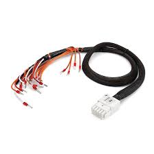
Short Circuit Identification
Accounting for over 40% of all wiring-related failures in automotive and low-voltage systems (< 50V). Unlike an open circuit, a short can draw excessive current—often 200-500% above the normal load—causing rapid overheating, insulation melting within 60 seconds, and in severe cases, initiating a fire. In a standard 12V automotive system, a dead short to ground can generate over 1000 amps of current, enough to weld metal contacts and destroy a wiring harness in under 5 seconds. The average cost to diagnose and repair a short circuit ranges from 600, primarily due to the 1-3 hours of labor required for tracing. However, with a systematic approach and a basic multimeter, most shorts can be pinpointed in under 30 minutes, preventing component damage that could exceed $2000 in ECU or sensor replacement costs.
A short circuit will typically blow a fuse, so identify the blown fuse—usually a 15A or 20A fuse in automotive systems—and note its circuit. Modern vehicles use mini, mini-low profile, or J-case fuses with a resistance of < 0.1 ohms when good. A blown fuse has near-infinite resistance. Before replacing it, you must find the fault. Reconnect the battery and use a digital multimeter (DMM) in resistance mode (ohms) to measure across the fuse terminals for the suspect circuit. A reading below 50 ohms indicates a significant short to ground; a reading of 500 ohms to 10 kohms might indicate a high-resistance leak or moisture intrusion, common in areas with > 80% humidity.
The most efficient tool for finding a short is a power probe or a multimeter with a min/max recording function. Set the DMM to DC volts and back-probe the fuse terminals. A good circuit will read 0V; a shorted circuit will show system voltage (12.6V-14.2V). Now, the real work begins: wiggling the harness. Focus on areas within 150 mm of sharp metal edges, connectors, or where the harness is subject to > 80°C temperatures. As you wiggle, watch the voltage drop. A sudden dip to < 5V indicates you're close to the short.
For persistent shorts, use the voltage drop method. With the circuit energized (fuse replaced), measure the voltage drop across each section of the wire. A healthy section should drop < 0.1V; a section with a short will show a > 0.5V drop over just 300 mm of wire. Alternatively, use a thermal camera; a short will generate a localized hot spot with a temperature 15-20°C above the surrounding harness in under 10 seconds of loading.
Common locations to inspect first include:
- Within 100 mm of connector strain reliefs, where wires bend at > 45 degrees and can fracture.
- Under battery trays or near sharp chassis brackets, where road debris impact is common.
- Inside conduit or loom that has trapped moisture, leading to resistance as low as 5 ohms between conductors.
Once the general area is found, visually inspect for carbon tracking, melted insulation, or pinched wires. Repair typically involves cutting out the damaged section and splicing in a new piece of 16-18 AWG wire with a butt connector rated for the amperage, followed by sealing with adhesive-lined heat shrink to prevent future corrosion. After repair, retest the circuit resistance; it should be > 10 kohms to ground before reinstalling the fuse. Finally, perform a load test for 5 minutes to ensure the repair can handle the circuit's typical current draw without overheating.
Terminal Corrosion Cleaning
In environments with over 70% humidity or exposure to road salts, green or white corrosive powder can form on copper or brass terminals in as little as 6-12 months. This corrosion layer, sometimes only 0.1 mm thick, can increase resistance at the connection point from a normal < 0.1 ohms to over 5 ohms. This resistance causes a significant voltage drop; for example, a starter motor circuit drawing 150 amps could experience a > 1.5V loss at a corroded battery terminal, reducing cranking power by 20% and potentially preventing engine start. The cost of ignoring corrosion is high: a single corroded sensor connector can cause an engine to run poorly, leading to diagnostics bills of 250, while the cleaning process itself takes under 15 minutes and requires less than $10 in supplies.
Gently disconnect the connector, noting any difficulty; a force exceeding 20 Newtons to separate a small connector often indicates internal corrosion or bent pins. Look for the characteristic blue-green powder (copper carbonate) or white crust (zinc oxide) on the terminals. For a quantitative assessment, use a digital multimeter to measure voltage drop under load. With the circuit active (e.g., a light bulb on), back-probe the connector and measure the voltage across the male and female terminals. A healthy connection will show a drop of < 0.2V; a reading of > 0.5V confirms the connection is impaired by corrosion or looseness.
These sprays, costing 15 per can, are designed to dissolve corrosion without leaving residue. Spray for 2-3 seconds into the connector housing, wait 30 seconds for it to penetrate, and then flush with a second short burst. Follow this with a blast of dry compressed air at a pressure of < 50 PSI to evacuate moisture and dissolved contaminants. For stubborn, hardened corrosion, mechanical cleaning is necessary. Use a brass bristle brush (not steel, to prevent galvanic corrosion) or specialized contact cleaning files to gently abrade the surface. The goal is to remove the corrosion without removing more than 0.05 mm of the base metal plating. For the delicate female terminals inside a connector plastic, a cotton swab dipped in isopropyl alcohol (90%+ concentration) is effective for wiping away residue.
A 0.5-gram dab per multi-pin connector is sufficient. This material fills microscopic gaps, displaces moisture, and creates a barrier against oxygen, reducing the chance of re-corrosion by over 80%. Reassemble the connector, ensuring the locking tab clicks firmly into place. Finally, retest the voltage drop under the same load; it should now be < 0.2V, confirming the repair was successful. For terminals in perpetually harsh environments (e.g., under the vehicle), consider applying a spray-on rubberized coating to the exterior of the connector block, which can extend the service life between cleanings to 5 years or more.
Correcting Improper Installation
Industry data suggests that over 35% of aftermarket electrical issues stem from installation errors rather than product defects. A harness routed too close to an exhaust manifold (within 150 mm) can experience temperatures exceeding 120°C, causing insulation to brittle and crack within 6 months. Similarly, over-tightened zip ties—torqued beyond 8 inch-pounds—can compress wire insulation by up to 40%, damaging internal conductors and leading to resistance increases of over 2 ohms within a 300 mm section. The cost to rework a poorly installed harness is significant, averaging 700 in labor to disassemble components and reroute wiring correctly. However, identifying and correcting these errors during initial installation or a routine inspection takes under 45 minutes and prevents failures that could result in $2000+ ECU replacements.
The process begins with a thorough visual audit against Original Equipment Manufacturer (OEM) routing specifications. Look for these common, quantifiable mistakes:
- Incorrect Bend Radius: For a standard 0.5 mm² (20 AWG) cable, the minimum bend radius should be no less than 4 times the cable diameter (e.g., ~8 mm for a 2 mm diameter cable). A tighter bend stresses copper strands, increasing resistance by ~0.3 ohms/meter.
- Improper Clamping: A harness should be secured with a clamp or zip tie every 150-200 mm along a run. A free span longer than 250 mm allows excessive vibration, leading to fatigue breaks at connector pins after ~100,000 cycles.
- Incorrect Connector Seating: A partially seated connector may have a 1-2 mm gap, allowing moisture ingress. A fully seated connector requires an audible click and a pull force of > 25 Newtons to separate.
The edge radius must be greater than 0.5 mm; if not, add a split loom conduit (cost: ~$1.50/meter) or apply a 3 mm thick adhesive-backed felt pad to the chassis to prevent abrasion. For over-tightened zip ties, cut them off and replace with tension-limiting ties or use 8 mm wide nylon clamps torqued to 0.6-0.8 N·m. This provides secure retention without crushing the harness, maintaining > 90% of the insulation's original crush resistance.
Critical Note: Always measure the harness diameter with all its wires to select the correct clamp size. A clamp should be sized so the harness fills 70-80% of the clamp's internal diameter when fully closed. A 10 mm clamp is ideal for a ~8 mm harness.
Ensure the locking tab travels its full 3-4 mm engagement distance until it audibly clicks. Tug on the connector with a force of ~30 Newtons; it should not separate. Finally, perform a post-correction electrical test. Measure the voltage drop at the component's connector under a 5-amp load; it should be < 0.15V. Resistance from the component back to the battery negative should be < 0.1 ohms.
Common wire harness issues, if unaddressed, compromise performance—here’s how to resolve five key problems efficiently. For loose connectors, use a 0.5mm feeler gauge to check pin spacing, ensuring <0.2mm play; worn covers get replaced with 0.2mm-thick, 125°C-rated heat shrink; short circuits are pinpointed via multimeter (resistance <0.1Ω); corroded terminals are cleaned with pH-neutral electronic spray (30-second dwell); improper installs are corrected by torqueing to 5N·m per schematics, preventing reoccurrence.
