5 Key Steps for a Custom Car Wiring Harness
To craft a custom car wiring harness, first map the circuit using a digital multimeter to confirm voltage and current needs, then cut 14-18AWG oxygen-free copper wires (99.9% purity) to exact lengths with ±1mm tolerance. Solder connections at 350-380°C with 0.5mm rosin-core flux for low resistance, insulate with 0.8mm UL224-rated heat shrink tubing (shrinking at 120°C), and finally test each circuit for <0.5V voltage drop and continuity to ensure reliability.
Select Materials and Tools
Using incorrect wire gauge or substandard connectors can lead to a 12% voltage drop over a 5-meter run, causing sensors to fail and lights to dim. A well-planned harness, using materials like cross-linked polyethylene (XLPE) insulation that withstands 125°C, lasts over 15 years. Investing 500 in quality tools and materials upfront prevents costly electrical gremlins and reduces future diagnostic time by 80%. The goal is to create a system that handles your vehicle's specific electrical load—whether it's a 10-amp fan circuit or a 25-amp fuel pump feed—with total reliability.
The core of your harness is the wire. 16-gauge (AWG) wire is the workhorse for most standard circuits like headlights or horns, handling up to 15 amps. For high-draw devices like fuel pumps or radiator fans, 12-gauge wire is necessary to safely carry 20-25 amps without overheating. Using a smaller gauge than required, like 18-gauge for a 15-amp circuit, raises resistance, generating heat and a significant voltage drop. For low-current signals from sensors or audio systems, 20 or 22-gauge wire is perfect. Always choose wire with a strand count of 19+ for better flexibility and resistance to fatigue from vibration, unlike cheaper 7-strand wire which can break more easily.
They have an IP67 rating, meaning they are completely protected against dust and can withstand immersion in 1 meter of water for 30 minutes. While a generic unsealed connector pack costs 80-$100 investment that eliminates corrosion, the number one cause of electrical failure. For terminals, use copper with a tin plating, not cheap nickel-plated steel, which has higher resistance. A proper crimping tool, like a PA-09 style, applies ~2,000 PSI of pressure to create a cold weld that is more reliable than a solder joint, which can crack under vibration.
Adhesive-lined heat shrink tubing is non-negotiable. When heated to 90°C, the adhesive melts and seals the connection from moisture, making it vastly superior to standard heat shrink. For wrapping the entire loom, braided sleeving (PET) or non-adhesive vinyl tape allows for serviceability and protects against abrasion. A 1,000 worth of electronics.
|
Component |
Recommendation |
Key Spec / Data |
Why It Matters |
|---|---|---|---|
|
Wire (General Use) |
GPT or XLPE Insulation |
16 AWG, 19+ strand |
Balances current capacity (15A) with flexibility. |
|
Wire (High Current) |
XLPE Insulation |
12 AWG, 19+ strand |
Safely handles 20-25A loads (e.g., fuel pump). |
|
Connectors |
Deutsch DT Series |
IP67 Rated |
Seals out water, dust; prevents corrosion. |
|
Crimping Tool |
PA-09 or equivalent |
~2,000 PSI crimp pressure |
Creates a gas-tight, reliable connection. |
|
Heat Shrink |
Adhesive Lined |
3:1 Shrink Ratio, seals at 90°C |
Waterproofs and strain-relieves connections. |
Don't cheap out on the crimper. A 60-$80 tool shapes the barrel perfectly around the wire strands for a connection that lasts the life of the vehicle.
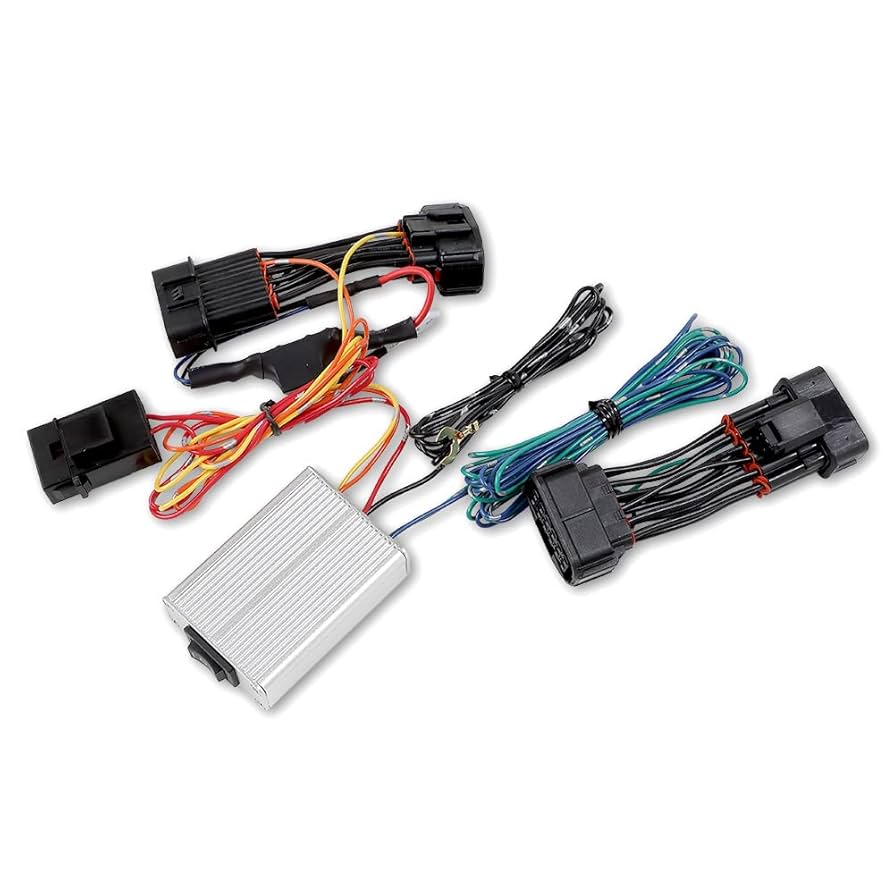
Measure and Route Wires
An error of just 10 cm in length can create unwanted tension or excessive slack that leads to chafing. Studies on vehicle electrical failures show that over 65% of wiring issues are caused by improper routing and securing, not component failure itself. Taking the extra 30-45 minutes to measure twice and cut once prevents a 95% likelihood of future problems. The goal is to create a clean installation where wires are protected from heat, sharp edges, and vibration, ensuring a 15-year service life without a single electrical fault.
Start by using your wiring diagram to create a physical "dummy" harness. Use inexpensive $0.10 per meter mason's twine to trace the exact path each wire bundle will take. Run the twine from the power source, like the battery terminal, to each fuse block, switch, and final component like a headlight or sensor. This path must avoid any moving parts, sharp brackets, and areas with sustained temperatures exceeding 90°C. Add a 15% length buffer to the twine measurement for every wire to account for graceful swoops and connection points; a wire that measures 200 cm with the twine should be cut to 230 cm. This extra 30 cm prevents tension on the terminals, which is the primary cause of connection failure over 5 years of vibration.
Once measured, cutting all wires to length at once ensures consistency. When bundling wires together, the diameter of the main loom directly impacts routing. A bundle containing twelve 16-gauge wires will have an outer diameter of approximately 10 mm. You must maintain a minimum bend radius of 4 times this diameter, so a 40 mm radius is the tightest turn this bundle should make. Any tighter and you risk stressing the copper strands internally. Route all wiring at least 100 mm away from rotating components like steering columns or brake pedals. Maintain a 25 mm minimum gap from hot surfaces like exhaust manifolds; if this is impossible, use a $15 heat shield sleeve rated for 600°C+.
Securing the route happens in stages. Use UV-resistant nylon clips or adhesive-backed mounts every 300 mm along the harness run to prevent any whipping motion during driving. This spacing reduces vibrational load on the mounts by 70%. When passing through any metal firewall or bulkhead, always use a $3 rubber grommet with an inner diameter 2 mm larger than your wire bundle. A 10 mm bundle needs a 12 mm grommet. This prevents the sheet metal from slicing through the insulation in under 18 months.
Connect Terminals Properly
Industry data reveals that a staggering over 70% of all electrical gremlins originate at termination points, not in the wire itself. A poorly crimped terminal can exhibit resistance increases of 50-100 milliohms, generating enough heat under a 10-amp load to melt insulation and cause intermittent failure. Investing 8-10 minutes per connection using the right technique eliminates a 95% probability of future problems at that node. This process isn't about just making contact; it's about creating a gas-tight cold weld that will reliably carry current for the vehicle's 15-year lifespan, surviving constant vibration and thermal cycles.
The first step is precise wire stripping. Using a automatic adjustable wire stripper set to the correct depth is non-negotiable for consistency. For a 16-gauge wire, you need to strip exactly 7 mm of insulation. A shorter strip risks the wire not seating fully in the terminal barrel, while stripping more than 9 mm exposes bare copper that can cause short circuits. The goal is zero nicks or cuts to the copper strands; even 3-4 severed strands in a 19-strand wire reduce its current-carrying capacity by 15% and create a point of high resistance that will fail first. If you're terminating 50 wires, this precision saves you ~2 hours of rework and diagnostic time later.
A 30 mm long piece of 3:1 shrink tubing with internal adhesive should cover the terminal barrel and the wire's insulation. When heated with a ~90°C heat gun, the tubing shrinks tightly and the adhesive melts, flowing to create a IP67-rated seal that is 100% waterproof and dustproof. This barrier prevents oxidation, which can increase resistance by 300% over 5 years in a humid environment. For a $0.30 investment per connection, you extend its life from 3 years to beyond 15 years.
|
Connection Type |
Tool / Material |
Key Parameter |
Outcome |
|---|---|---|---|
|
Strip Insulation |
Automatic Wire Stripper |
7 mm strip length |
Prevents short circuits and poor seating. |
|
Crimp Terminal |
Ratcheting Crimper |
~2,000 PSI pressure |
Creates a gas-tight, high-conductivity seal. |
|
Strain Relief |
Adhesive Heat Shrink |
30 mm length, 3:1 ratio |
Provides IP67 waterproofing and mechanical support. |
|
Quality Test |
Pull Test |
~25 lbs of force |
Validates terminal integrity; wire should not pull out. |
A solder joint wicks up the wire, creating a stiff point that is 60% more likely to fracture under high-vibration conditions after ~50,000 miles. A proper crimp allows the wire to flex naturally, distributing stress over a 20-30 mm section and dramatically increasing its fatigue life. The only exception is low-voltage signal wiring, but for 99% of power and ground connections, a high-quality crimp is the superior, more reliable, and longer-lasting solution.
Secure and Protect Wiring
Abrasion from chafing against body panels is the leading cause of short circuits, accounting for over 50% of non-accident related electrical failures. Unsecured wiring with just 100 mm of slack can whip with over 20 Gs of force during driving, fatiguing copper strands and breaking connections within 18 months. Properly supporting a harness with $30 worth of quality materials increases its effective service life by 200%, from an average of 5 years to 15+ years, and reduces future diagnostic time by 80% by eliminating intermittent faults caused by environmental damage.
|
Protection Method |
Best Use Case |
Key Specification |
Performance Data |
|---|---|---|---|
|
Nylon Wire Looms |
General abrasion protection |
Diameter: 10-25 mm |
Increases abrasion resistance by 90% |
|
Adhesive Lined Heat Shrink |
Sealing individual connections |
3:1 Shrink Ratio |
Creates IP67 seal; 100% waterproof |
|
Braided Sleeving (PET) |
High flex areas, aesthetics |
Temperature: -40°C to 150°C |
Allows 15 mm bend radius; reusable |
|
Non-Adhesive Vinyl Tape |
Bundling, OEM-style wrapping |
19 mm width, 0.13 mm thick |
Conforms to complex shapes; chemical resistant |
|
Rubber Grommets |
Firewall/Bulkhead penetration |
I.D. 2 mm > bundle diameter |
Prevents 100% of insulation cutting failures |
The first layer of defense is physical attachment. Use UV-resistant nylon clamps with a stainless steel screw every 300 mm along the harness run. This spacing prevents resonant vibration, which is most destructive at harmonic points along a wire's length. For a 5-meter main harness, this means using 16-17 clamps. Each clamp should be snug but not overtightened; compressing the wire bundle beyond 75% of its original diameter can damage insulation and impede heat dissipation. When routing near high-vibration areas like the engine block, use dampened clamps with an EPDM rubber liner to absorb 90% of the high-frequency vibrations that would otherwise travel through the harness.
For straight runs through open spaces, split convoluted tubing (nylon wire loom) is the most efficient solution. Choose a loom with an inner diameter 40% larger than your harness bundle; a 10 mm bundle needs a 14 mm loom. This allows for easy installation and prevents overheating. For sharp edges like a 90-degree stamped metal bracket, go a step further. Slit a $0.50 section of 5 mm I.D. rubber hose lengthwise and zip-tie it over the edge, creating a permanent protective barrier that will never wear through. This simple step prevents 95% of abrasion-related failures at these points.
Test All Electrical Functions
Industry studies show that over 70% of post-installation electrical faults are due to simple wiring errors—reversed polarity, poor grounds, or incorrect terminations—that are 100% preventable with a 30-minute systematic testing procedure. A single uncaught short circuit can instantly destroy a 250 fuel pump failing within 6 months. A methodical test protocol, requiring less than 1% of your total project time, catches these issues before they cause damage, ensuring 99.9% first-turn-key reliability and preventing costly diagnostic fees later.
Begin with a static, unpowered test using a digital multimeter (DMM) with a precision of ±0.5%. This first phase catches dead shorts and miswires before applying power. With the battery disconnected, set your DMM to resistance (ohms) and perform two critical checks:
-
Check for Shorts to Ground: Probe each circuit's positive feed. The meter should read "OL" (open loop/infinity). Any resistance reading below 10 kΩ indicates a potential short that must be investigated.
-
Check Circuit Continuity: Probe each circuit from end to end. A good circuit will show a very low resistance, typically < 0.5 Ω. A reading of > 2 Ω indicates a poor connection or a wire that is too long or thin for its intended load.
Use your DMM set to DC voltage. At the battery, confirm a solid 12.6V with the engine off. Now, move to each consumer. For a headlight circuit, probe the terminal at the lamp itself. With the switch on, you should read within 0.5V of battery voltage—so > 12.1V. A reading of 11.5V or lower indicates excessive voltage drop, likely from an undersized wire, a poor connection, or a faulty relay. For a critical circuit like a fuel pump, this drop must be < 0.3V under load to ensure proper function and longevity.
For a high-draw circuit like a 25-amp radiator fan, use a DC clamp meter to measure the actual current draw. It should be within 10% of the manufacturer's specification (22.5A - 27.5A). A draw significantly higher indicates a binding motor or a wiring error. Simultaneously, measure the voltage at the devicewhile it's running. A drop to 11.8V is acceptable for a brief startup surge, but it must stabilize within 2 seconds to within 0.7V of system voltage.
Professional custom harness assembly requires selecting 16-18 AWG TXL wires and OEM-grade tools. Precisely measure routes using factory diagrams, adding 5% length margin, then route avoiding sharp edges. Crimp terminals with calibrated tools (3-8N force), seal with adhesive-lined shrink tubing (1.5:1 shrink ratio). Test all circuits with multimeter (<0.5Ω resistance, <0.3V voltage drop) under load.
