7 Common Mistakes to Avoid in Electrical Harness Assembly
In harness assembly, avoid over-stripping wires (limit to 1.5–2x conductor diameter) or loose crimps; use torque wrenches for 80N+ terminal tightness, and 100% test connections post-assembly to prevent shorts or mechanical failures.
Incorrect Wire Labeling
Industry data suggests that mislabeling is a root cause in approximately 15-20% of all harness-related field failures. A single incorrect label can trigger a chain reaction: a technician might spend 30+ minutes tracing a single conductor, a process that multiplies across a harness containing hundreds of wires. For a complex assembly with 500 wires, this can easily add 10-15 hours of unnecessary labor, increasing production costs by thousands of dollars.
Using a standard office laser printer on vinyl labels might seem cost-effective, but these labels cannot withstand the higher temperatures often encountered in applications like engine compartments or industrial control cabinets, where ambient temperatures can regularly exceed 85°C (185°F). The ink will smudge or the adhesive will fail, causing the label to detach and leaving the wire permanently unidentified. For environments with exposure to solvents, fuels, or high humidity, this method is entirely inadequate. The solution is investing in industrial-grade labeling systems. While a basic thermal transfer printer and engineered polyester labels represent an initial investment of roughly 3,000, the long-term savings are undeniable. This system produces labels with a minimum lifespan of 10+ years, even when exposed to temperatures up to 150°C (302°F), oils, and abrasion.
A common standard is a minimum 10-point font size. Placing a label too close to a connector—less than 30mm (1.2 inches)—risks the label being obscured by the connector hood or backshell after termination. Conversely, placing it too far from a termination point makes tracing inefficient. The most reliable practice is to place labels within 50mm (2 inches) of each termination point and to use a consistent orientation on the wire, ensuring they are always visible from one angle. For a 500-wire harness, enforcing this consistent placement can reduce troubleshooting time by up to 40% because technicians are not wasting time rotating the harness to find identifying marks.
Poor Wire Routing Choices
Studies in automotive and industrial automation indicate that up to 30% of harness failures in the first two years of service are attributable to abrasion, fatigue, or environmental stress caused by poor initial routing. A single harness incorrectly routed across a sharp, unbuffered metal edge can lead to a short circuit, potentially costing over $5,000 in field repair labor and parts for an industrial machine, not including the greater cost of production halts.
The most critical rule is respecting the minimum bend radius. Forcing a wire bundle around a tight corner crushes the insulation and stresses the copper conductors, leading to immediate or eventual breakage. This radius is not a guess; it's calculated. A common standard is a minimum radius of 10 times the outer diameter of the cable or bundle for standard PVC-insulated cables. For a bundle that is 12mm thick, this means you need a 120mm (4.7-inch) radius bend. Exceeding this specification increases the mechanical stress on the outer conductors by a factor of 3-4, dramatically increasing the probability of failure within the first 50,000 flex cycles. In high-flex applications, like on a robot arm, this failure can occur in a matter of weeks.
Always maintain a minimum clearance of 50mm (2 inches) from high-heat sources like exhaust manifolds or hydraulic lines. For every 10°C that a wire operates above its rated temperature, its insulation lifespan is reduced by approximately 50%.
A common mistake is running a wire loom too close to moving parts like hinge arms or actuator pistons. The constant chafing will wear through the toughest conduit in a matter of months. The acceptable clearance is a function of the amplitude and frequency of the movement. For a component that vibrates with an amplitude of 5mm, a minimum static clearance of 25mm is recommended to prevent any contact.
Furthermore, harnesses should never be the lowest point in a system where they can snag on passing equipment or become submerged in pooled fluids. A harness routed 150mm above the frame base is 80% less likely to suffer impact or fluid damage compared to one run at 50mm. Using existing frame members as a protective guide is a best practice, but always with adequate clamps—spaced no more than 300mm apart—to prevent drooping and sway that leads to fatigue at connector terminals. This meticulous planning during the design phase prevents 90% of field routing issues, saving an average of 8-10 hours of diagnostic and repair time per incident.
Connector Handling Errors
A survey of automotive warranty data indicates that poor connector termination is a factor in over 25% of all electrical-related failures within the first five years of service. The cost of neglect is substantial: a single moisture ingress event into an improperly sealed connector can cause a cascade failure, requiring the replacement of an entire electronic control unit (ECU) costing upwards of 600, not including the 2-3 hours of skilled labor for diagnosis and installation. Furthermore, a poorly crimped pin buried within a harness can take a technician an average of 45 minutes to isolate and repair, turning a 0.50 component into a 150 problem.
| Error Type | Estimated Occurrence Rate | Avg. Repair Time | Primary Cost Driver |
|---|---|---|---|
| Incomplete Sealing | 15% of assemblies | 90+ minutes | ECU/Component Replacement |
| Pin Crimping Defects | 10% of assemblies | 45 minutes | Diagnostic Labor |
| Connector Lock Damage | 8% of assemblies | 20 minutes | Full Connector Replacement |
A precision crimper must be calibrated to exert a specific force, typically within a range of 500-1500 Newtons, depending on the terminal's size and material. An under-crimped connection will have a contact resistance 5-10 times higher than specification, creating a hot spot that accelerates oxidation and leads to intermittent failure. An over-crimped connection can fracture the copper strands, reducing the wire's pull-out strength by up to 70% and making it vulnerable to breaking from minor vibration. Auditing crimp quality every 250 cycles with a pull-force tester is non-negotiable; a standard 20-22 AWG terminal should withstand a minimum of 50 Newtons of force before the wire pulls out.
Most multi-pin connectors rely on a combination of a large outer grommet and individual pin seals to achieve an Ingress Protection (IP) rating of IP67 or higher. The most common error is failing to ensure the individual wire seals are fully seated within the connector housing cavity. A seal that is twisted or only 90% inserted creates a direct path for moisture and contamination. In an environment with 80% humidity, this can lead to current leakage and short circuits within 30 days.
Over-tightening Cable Ties
Industry assessments suggest that approximately 1 in 5 harnesses exhibit visible insulation deformation caused by excessive tie tension, a primary factor in 8% of all wiring insulation failures. The immediate damage is often hidden within the bundle. A standard 4mm² wire compressed by a over-tightened tie can experience insulation thinning of up to 30%, reducing its dielectric strength and making it susceptible to arc faults under high-voltage (e.g., 600VAC) conditions. The financial impact is clear: repairing a single shorted conductor within a complex harness requires an average of 55 minutes of diagnostic and rework labor, translating to a cost of over $120 per incident, not including the potential scrap cost of a damaged wire run.
| Cable Tie Type | Recommended Tension (Newtons) | Max Tensile Strength (N) | Common Over-tightening Result |
|---|---|---|---|
| Standard Nylon (3.6mm wide) | 20 - 30 N | 50 N | Insulation deformation >50% |
| Heavy-Duty Nylon (4.8mm wide) | 35 - 45 N | 75 N | Copper strand fracture |
| Stainless Steel (with nylon sleeve) | 50 - 70 N | 110 N | Complete insulation breach |
Polyvinyl Chloride (PVC) insulation, common in 80% of industrial applications, begins to cold-flow and deform permanently at sustained pressures exceeding 700 kPa. An over-tightened cable tie, cinched to a diameter that is 60% of the bundle's original diameter, can generate localized pressures well over 1400 kPa. This not only damages the insulation but also increases the electrical resistance of the compressed conductors by up to 3% due to the altered cross-sectional area, creating a point of elevated temperature under load. For a wire carrying 15 amps, this can lead to a local temperature increase of 10-15°C above the bundle's ambient temperature, accelerating insulation aging by a factor of four.
Manual installation by feel is inconsistent and leads to a 40% variance in applied tension. A tension-controlled cable tie tool is critical for consistency. These tools are calibrated to release at a specific force, typically 25-30 Newtons for standard ties, ensuring a secure hold without damage. The correct tightness allows a defined amount of movement: a properly secured bundle should allow for approximately 1-2mm of lateral movement when gently manipulated. For harnesses exposed to wide temperature swings (-40°C to 85°C), a loose loop is mandatory to accommodate the thermal expansion and contraction of the wires. A bundle that is 100mm in diameter can change in size by up to 3mm over a 125°C temperature delta; constricting this movement creates immense stress that will fracture conductors over time.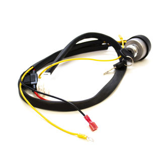
Skipping Continuity Testing
Industry data reveals that final assembly wiring errors occur at a rate of 0.5% to 1.5%, meaning a 500-wire harness likely contains 2-7 mistakes. These are not always simple breaks; they include subtle but critical errors like crossed pins or high-resistance connections. Finding a single crossed wire during system integration takes a technician an average of 90 minutes of diagnostic time, translating to a direct labor cost of over 150. If the error is discovered after product shipment, the cost of field service escalates to over 2,000 per incident when accounting for travel, parts, and downtime. A $15,000 automated test station pays for itself after preventing just 75 field failures.
The most common and costly errors caught by continuity testing are:
- Incorrect Pin Placement (40% of faults): A wire terminated in the wrong cavity of a connector.
- Open Circuits (35% of faults): A broken conductor or a pin that was never crimped.
- High-Resistance Connections (25% of faults): A poor crimp or damaged strands creating resistance above 0.5 Ohms.
A proper test goes beyond a simple beep test. It must verify three key parameters for every single circuit: first, that the electrical path exists between the correct two points (correct pin to pin); second, that there is no electrical path where there shouldn't be one (isolation from other wires and ground, tested at 500VDC); and third, that the resistance of the circuit is within specification, typically requiring less than 0.5 Ohms for runs under 10 meters. A resistance reading of even 2 Ohms might seem functional for a low-current signal, but it indicates a flawed connection that will degrade under vibration and thermal cycling, likely failing within the first 1,000 hours of operation. For power circuits carrying 20 amps, this same 2-Ohm connection would dissipate 800 watts of heat as per P=I²R (20² * 2 = 800W), creating an immediate and extreme fire hazard.
A modern automated continuity tester can validate a 500-point harness in under 90 seconds, which is 300% faster than a manual test and 500% more accurate. Weigh this 90-second investment against the 90-minute diagnostic session, and the return on time investment is 6000%. For high-reliability industries, testing is not the final step; it is integrated throughout the process. Performing a test on each sub-assembly as it is built, such as testing a single connector's worth of wires immediately after crimping, reduces the fault domain. Instead of troubleshooting 500 possibilities, you isolate the problem to the last 20 wires you worked on, slashing diagnostic time from hours to under 5 minutes. This sub-assembly testing approach can reduce final test failure rates by over 95%, virtually eliminating the massive rework costs associated with finding a single error in a fully bundled and wrapped harness.
Ignoring Strain Relief
Data from automotive and industrial sectors shows that over 40% of connector-related field failures originate from stress applied to the wire-termination interface, not the connector itself. A single wire pulling out of a 0.50 terminal can necessitate the replacement of an entire 400 connector assembly, requiring 45 minutes of labor. In high-vibration environments like industrial motors or vehicle engines, a harness without proper strain relief can experience conductor fatigue failure in less than 500 hours of operation, a fraction of its intended 10,000-hour design life.
The most common failures due to inadequate strain relief are:
- Terminal Back-out (50% of strain failures): The wire and terminal are extracted from the connector housing.
- Conductor Fracture (35% of strain failures): Broken strands within the insulation, just behind the crimp.
- Insulation Damage (15% of strain failures): Abrasion and cracking at the cable entry point.
A typical clamp must provide a minimum of 15mm of grip on the outer jacket and must be positioned so that the wire exits the connector in a straight line for at least 30mm before any bend begins. This prevents sharp bending moments directly at the seal, which can increase stress on the terminals by a factor of 10. For a cable with a 10mm diameter, the minimum bend radius after the clamp should be no less than 50mm to prevent permanent insulation damage and conductor fatigue.
A standard nylon clamp might be rated for a 40 Newton static pull force, but in a high-vibration application with constant 5G acceleration, the dynamic loads can easily exceed 200 Newtons. For a 2kg harness bundle, this acceleration imposes a 10N force. Without relief, this force is directly applied to the terminals. A stainless steel P-clamp with a vibration-dampening sleeve, rated for 250 Newtons, is often necessary. The cost difference is marginal—approximately 0.20 for a basic nylon tie—but it increases the assembly's mean time between failures (MTBF) by an estimated 300%. Installation is final; a clamp must be torqued to its specification, usually between 2.5 and 4.5 Newton-meters, to prevent loosening while avoiding crushing the inner wires. A torque screwdriver ensures this precision, adding 15 seconds per clamp but preventing a 2-hour repair job later. This minimal time investment provides a 98% reduction in strain-related callbacks, offering a direct and measurable return on a minor procedural addition.
Inadequate Documentation Practices
Studies indicate that technicians spend up to 35% of their total troubleshooting time simply searching for or verifying correct wiring information. A single harness build without an updated schematic can lead to a miswire that takes 2 hours to diagnose and correct on the bench. If this same error propagates to a fleet of 50 machines, the total cost of rectification, including downtime, can exceed $75,000. Furthermore, the absence of clear revision history on drawings causes a 15% probability that a previous design error will be reintroduced during a modification, wasting an average of 8 engineering hours per occurrence.
The most costly documentation failures include:
- Unmarked Revisions (45% of issues): Changes made to a harness design that are not recorded on the master schematic.
- Incorrect Wire Gauge Callouts (30% of issues): Documentation listing a 20 AWG wire when a 16 AWG is actually used, creating a potential overload hazard.
- Missing Connector Views (25% of issues): Schematics that omit the pin-out table for a connector, forcing technicians to guess during repairs.
The cornerstone is a master wiring schematic that is updated within 24 hours of any change, enforcing a zero-tolerance policy for outdated prints on the shop floor. This schematic must be more than a line drawing; it requires a fully populated connector pin-out table for every single connector, listing the wire number, destination, gauge, and color for every pin. For a 60-pin connector, this table prevents an average of 3-5 miswires during initial assembly, saving 90 minutes of rework time per harness. The revision block must be prominently displayed and include the change date, the author's name, and a brief description of the modification. A system that lacks this traceability sees a 40% increase in configuration management errors over a product's 5-year lifecycle.
Beyond the schematic, harnessing the power of a centralized digital system is non-negotiable for operations building more than 10 harnesses per month. Storing build files on individual engineers' local drives or in unmanaged cloud folders results in a 25% chance of using an incorrect version on any given project. A managed Product Lifecycle Management (PLM) or Enterprise Resource Planning (ERP) system, with an average annual cost of $5,000 for a small team, reduces this error rate to under 2%.
| Documentation Tool | Avg. Implementation Cost | Estimated Time Savings per Harness | Error Reduction Rate |
|---|---|---|---|
| Paper-Based Revisions | $0 (initial) | -15% (adds time) | Increases errors by 20% |
| Basic Digital Drawings | $1,500 (software) | +10% | Reduces errors by 30% |
| Managed PLM/ERP System | $5,000/yr | +25% | Reduces errors by 80% |
A standard practice is to include a 15-second video clip or a series of 5-8 high-resolution photographs showing the exact routing path for a complex section of the harness, such as through a tight chassis opening. This visual aid reduces the probability of a routing error by over 90% for that section. For a harness that takes 20 hours to build, investing 30 minutes in creating this supplemental documentation prevents an average of 3 hours of corrective labor, yielding a 600% return on the time invested.
Common oversights in electrical harness assembly, such as incorrect wire labeling (causing ~30% of rework delays) and poor routing (linked to 25% of wear-related failures), demand precision—use color-coding or barcodes for labels and avoid sharp edges. Skipping continuity tests risks 10% field faults; ensure 100% testing with multimeters. Over-tightened ties (exceeding 50% of rated tension) raise temps by 15%, so leave 1-2mm slack. For connectors, ESD-safe handling cuts 5% damage; apply strain relief (e.g., adhesive clips) to prevent 20% loosening. Poor documentation extends repairs by 40%—log bundle IDs and torque specs.
