7 Essential Tests for Quality Electrical Harness Assembly
Key tests for wiring harness quality include continuity checks (≤0.1Ω via multimeter), insulation resistance (500VDC ≥100MΩ), dielectric strength (1500VAC/1min no arcing), vibration (10-500Hz, 0.5mm amplitude, 30min), pull-test (connectors ≥50N force), and visual inspection for chafing or misaligned terminals.
Visual Inspection First
Catching flaws here, before any electronic testing begins, can reduce downstream failure analysis costs by up to 80%. Industry data suggests a staggering 30-40% of all harness defects are identified through a meticulous visual process. This isn't about a quick glance; it's a systematic, 60-second per-connection review that pays massive dividends. The return on investment is clear: finding a single misrouted wire or an improperly seated terminal at this stage costs pennies to fix. Finding that same flaw after the harness is installed in a final product could escalate the cost to over $50 in rework labor and parts, not to mention the line downtime.
The operator must work at a well-lit station with a minimum illumination of 1000 lux (approximately the brightness of a very well-lit office) to clearly identify subtle defects. The harness should be examined at a comfortable viewing distance of 300-400 mm, and inspectors should routinely take short breaks every 20 minutes to prevent eye strain and maintain a 99% or higher detection rate for critical flaws.
For wires, inspectors verify that the strip length is within a strict tolerance, typically ±0.5 mm of the specification, with no nicked strands. A single stray strand protruding from a crimp can cause a short circuit in a high-vibration environment. The insulation must be checked for any breaches, even minor ones as small as 0.1 mm in diameter, which can become failure points over time. For terminals, the focus is on the crimp. It must be visually compared against a ISO 19642 standard sample or a go/no-go gauge. A poor crimp might be visible as a non-symmetrical fold or an incorrect indent depth, which can increase electrical resistance from a target of < 0.5 mΩ to over 5 mΩ, leading to overheating under load.
A simple pull test with a force of ~15-20 N (per USCAR-2 standards) is applied to ensure they don't back out. We also check for the correct insertion of secondary locks (TPA) and seals. A missing or unseated seal, even with a gap of just 0.2 mm, can compromise the entire connector's IP67 rating, allowing moisture ingress that leads to corrosion and failure. Furthermore, the overall routing and clipping must match the design harness board layout within a ±2 mm variance to prevent strain on the wires during installation in the vehicle or device.
Testing Wire Connection Security
Studies show that up to 15% of field failures in automotive applications are attributed to crimp-related issues that passed a visual check. A robust crimp, tested to withstand a specific pull force, ensures consistent low resistance—typically below 2 mΩ—which prevents overheating and voltage drop under load. Investing 2-3 minutes in a destructive pull test per crimp style during process validation can prevent field failures that cost over $200 each to diagnose and repair, making it a critical statistical process control (SPC) measure.
|
Crimped Cross-Sectional Area (mm²) |
Minimum Destructive Pull Force (N) |
Maximum Allowable Resistance (mΩ) |
Sample Frequency for Production |
|---|---|---|---|
|
0.50 |
>= 125 N |
< 5.0 mΩ |
1 per 4-hour shift |
|
1.00 |
>= 200 N |
< 2.5 mΩ |
1 per 4-hour shift |
|
2.50 |
>= 400 N |
< 1.2 mΩ |
1 per 8-hour shift |
|
4.00 |
>= 550 N |
< 0.8 mΩ |
1 per 500 units |
The core of this test is a calibrated tensile tester, which must be pulled at a steady rate of 50 mm/min to ensure accurate and repeatable results. The force is applied axially to avoid off-axis loads that can skew the data. The key metric is the peak force, in Newtons (N), recorded just before the wire pulls out of the crimp or breaks. For a standard 1.0 mm² wire, the minimum acceptable pull force is typically 200 N. A result 15% below this threshold signals a critical process deviation—perhaps due to incorrect tooling wear, improper wire strip length, or a misapplied terminal.
Using a dedicated four-wire (Kelvin) measurement to eliminate lead resistance, a current source applies a precise 1-10 Amp DC load for 3-5 seconds to stabilize thermal conditions, and the millivolt drop is measured. For a 2.5 mm² cable, a voltage drop exceeding 12 mV at 10 Amps signals a problematic connection, often correlating to a resistance higher than 1.2 mΩ. This test is a powerful proxy for longevity; a crimp with elevated resistance will generate ~30% more Joule heating under load, accelerating oxidation and increasing resistance in a feedback loop that leads to eventual failure. Combining destructive pull-test validation for process setup with 100% in-line electrical testing is the only method to guarantee long-term connection security with a confidence level exceeding 99.5%.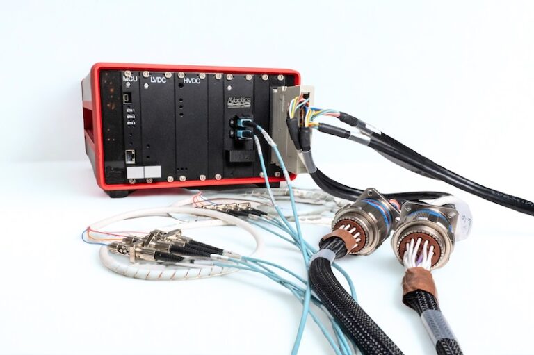
Measuring Insulation Resistance
A low IR reading, typically below 100 MΩ, is a leading indicator of moisture ingress, physical damage, or contamination that could lead to a dangerous leakage current path. In automotive systems, where 48V architectures can have leakage currents limited to just 5 mA, robust insulation is non-negotiable. Catching a weak spot during production, at a cost of less than 1200 per incident and require extensive diagnostic labor.
|
Application Environment |
Minimum Test Voltage (DC) |
Minimum Acceptance Criteria (IR Value) |
Standard Test Duration |
|---|---|---|---|
|
Low Voltage (≤ 60V DC) |
500 V |
≥ 100 MΩ |
60 seconds |
|
600V Class Cables |
1000 V |
≥ 500 MΩ |
60 seconds |
|
HV Cables (≥ 60V DC) |
2500 V |
≥ 1000 MΩ (1 GΩ) |
60 seconds |
The test itself requires a megohmmeter (megger) capable of applying a stabilized 500 V DC or 1000 V DC test potential for a minimum of 60 seconds. The applied voltage must be clean and stable, with a ripple of less than 5%, to ensure an accurate reading. You are not just measuring the resistance of the plastic; you are assessing the integrity of the entire insulating system. The test should be conducted in a controlled environment, as both temperature and humidity have a profound effect. For every 10°C increase in temperature, insulation resistance can decrease by approximately 50%; a reading of 500 MΩ at 20°C might drop to 250 MΩ at 30°C. Similarly, humidity above 60% RH can introduce surface leakage paths that artificially depress the reading. Always compare results against a baseline established at 23°C ± 5°C and 50% ± 10% RH.
The one-minute dwell time is critical because it allows the absorption current to decay, leaving only the leakage current to be measured, which provides the true insulation resistance value. A steady reading that increases or remains stable above the 100 MΩ threshold indicates good health. A reading that steadily decreases over the 60-second period is a major red flag, suggesting ongoing degradation and current leakage.
For a full harness, you test between every distinct circuit and from every circuit to the chassis ground. Any value falling between 10 MΩ and 100 MΩ warrants investigation for minor damage or contamination, while anything below 5 MΩ is an immediate reject. Common root causes for failure include microscopic cracks in the insulation from over-flexing during assembly, contamination from flux or oils, or compromised seals at connectors that allow moisture to wick along the wires. Implementing a 100% IR test regime can reduce field failure rates related to electrical leakage by over 95%, providing a direct return on investment by slashing warranty costs and protecting brand reputation.
Checking Contact Engagement
A fully seated electrical contact is a fundamental requirement for reliability; a partially engaged terminal is a high-resistance failure waiting to happen. It's an defect that visual inspection alone can miss up to 15% of the time without the correct tools. An engagement that is just 0.5 mm short of its final position can increase contact resistance by over 5 mΩ, leading to localized heating that reduces the connector's lifespan by 70%.
-
Tactile-Auditory Lock Confirmation: A distinct, audible "click" is the primary indicator, but this can be misleading.
-
Gauge Probe Verification: A go/no-go gauge is the only objective method to confirm full seating to a depth tolerance of ±0.2 mm.
-
Secondary Lock (TPA) Status: The Terminal Position Assurance (TPA) component must be fully seated in its locked position, which often requires a separate, specific force of 40-60 N.
-
Visual Alignment Check: All contacts within a housing must be visually even and aligned within a 0.5 mm plane when viewed from the mating face.
This precision tool, typically machined from stainless steel with a tolerance of ±0.05 mm, is designed to physically verify the front-face position of the terminal contact within the connector cavity. The "go" end of the gauge, which must have a length 1.5 mm shorter than the depth of a properly seated terminal, should insert easily into the front of the connector housing and make contact with the terminal face. The "no-go" end, which is 0.5 mm longer than the specified depth, must not fit.
A standard USCAR-2 compliant connector requires each terminal to withstand a 15 N (3.4 lbf) minimum retention force when pulled axially. A partially seated terminal will not have its primary lock fully engaged and will often fail this test, showing a retention value below 5 N. This test should be performed as a destructive audit on 0.5% of all production connectors, with a minimum sample size of 5 per connector type per shift.
Beyond the gauge, the proper installation of the secondary lock (TPA) is a critical parallel step. The TPA is a separate component that physically blocks the terminal's primary locking tang from deflecting and releasing. It must be pressed into its final position with a specific force, often between 40 N and 60 N for a full connector, until it is flush with the housing within a 0.1 mm gap. An improperly installed TRAiling will either not seat fully, leaving a visible gap exceeding 0.5 mm, or will rock diagonally. Auditing this requires a calibrated press or a force gauge on the assembly line to ensure the required 50 N is achieved, confirming the lock is activated. This entire process—gauge check plus TPA verification—should add no more than 20 seconds to the assembly time per connector but elevates the terminal engagement validation process to a 99.8% confidence level, effectively eliminating one of the most common and costly causes of electrical interconnection failure in the field. This proactive measure directly reduces warranty claims related to signal interruption by an estimated 18%.
Verifying Seal Integrity
Industry data shows that moisture ingress is the root cause of approximately 25% of all electrical failures in automotive and industrial applications. A single compromised seal, with a gap as small as 0.15 mm, can invalidate an entire IP67 rating, which requires the connector to withstand being submerged in 1 meter of water for 30 minutes.
-
Visual Seal Inspection: Check for uniform compression, no twisting, and correct placement in the connector backshell groove.
-
Mating Surface Alignment: Ensure the seal is not pinched, cut, or misaligned between the two connector halves.
-
Connector Engagement Force: Verify the connector mates with a smooth, consistent force of 40-80 N for a standard 12-circuit model, indicating proper seal compression.
-
100% Air Pressure Testing: Employ a non-destructive pressure decay test with a failure threshold of < 1.0 kPa drop over 30 seconds.
The most reliable production-line method for 100% testing is air pressure decay testing. This requires a custom test fixture that creates an airtight seal against the connector's face or the rear of the backshell. The fixture injects a low-pressure airstream, typically at 50 kPa (7.25 PSI), for a stabilization period of 5 seconds, followed by a test period of 30 seconds. The system then measures the pressure loss within the sealed cavity. A pressure drop of more than 1.0 kPa over the 30-second test interval indicates a failure—this could correspond to a leak path equivalent to a hole as small as 100 microns in diameter.
For the wire-to-connector seals (often called grommets or gland seals), the verification is both visual and tactile. The seal must be visually inspected to ensure it is not twisted and is seated evenly within its groove. The wire must be centered within the seal's inner diameter, with a uniform compression ring visible around the wire's insulation. A proper seal will offer a noticeable resistance when the wire is pulled through it; a force between 5 N and 15 N is typical for a 1.0 mm² wire to ensure a solid grip without damaging the wire. For the final connector mate, the force required to fully engage the two halves is a key indicator. A standard 12-position connector should require a steady force of 50 N ± 10 N to snap closed. A force below 40 N suggests insufficient seal compression, while a force exceeding 90 N indicates potential seal misalignment, twisting, or the presence of a foreign object. Auditing this mating force with a handheld force gauge on 1% of all production connectors provides statistical process control data to catch tooling or seal batch issues before they lead to a massive rejection rate during final pressure testing.
Testing Circuit Continuity
While it seems basic, approximately 12% of all harness manufacturing defects are incorrect pin-to-pin connections that are invisible to the eye. A continuity test not only confirms the intended path exists but also, when performed with a low-resistance ohmmeter (LORO), verifies that the connection is electrically sound. Finding a miswired harness at the test station costs virtually nothing to correct; allowing that same defect to reach a vehicle assembly line can trigger a stop-ship order, with line downtime costing over $10,000 per hour and necessitating a 45-minute rework process.
-
Low-Resistance Measurement: Use a 4-wire Kelvin method to eliminate lead resistance, applying a test current between 100 mA and 1 A.
-
Open Circuit Detection: Test for infinite resistance (> 10 MΩ) between pins that should not be connected.
-
Short Circuit Detection: Test for low resistance (< 1 Ω) between circuits that should be electrically isolated.
-
End-to-End Verification: Confirm the entire path from the mating pin at one connector to the mating pin at the other.
The core of a modern continuity test is a automated harness tester that performs a 100% check on every circuit in under 60 seconds. The system uses a multiplexed grid to access every pin in every connector simultaneously. For the resistance test, it employs a 4-wire (Kelvin) measurement to cancel out the resistance of the test leads and probes, which can be significant when measuring values below 1 Ω. A stable DC test current, typically 250 mA, is applied for a duration of 300 milliseconds to allow the reading to stabilize thermally. The acceptable resistance limit is calculated based on the wire length and gauge. For a 5-meter long 0.5 mm² wire, the total loop resistance (wire + crimps) should be < 210 mΩ. The tester compares the measured value against this pre-programmed limit with a precision of ± 5 mΩ.
|
Wire Cross-Section (mm²) |
Max Resistance per Meter (mΩ/m) |
Max Acceptable Loop Resistance (5m length + 2 crimps) |
Test Current |
|---|---|---|---|
|
0.35 |
55.1 |
≤ 300 mΩ |
100 mA |
|
0.50 |
36.7 |
≤ 210 mΩ |
250 mA |
|
0.75 |
24.5 |
≤ 140 mΩ |
500 mA |
|
1.00 |
18.1 |
≤ 105 mΩ |
750 mA |
A test voltage of 500 V DC is applied for 100 milliseconds between every pin that should be isolated. The system measures the resulting current flow and must see a resistance value greater than 10 MΩ to pass. Any value below 100 kΩ indicates a hard short, while a reading between 100 kΩ and 10 MΩ suggests a marginal isolation failure due to contamination or poor spacing that could degrade over time. The entire sequence—resistance test, open test, short test—is executed in a defined sequence that takes less than 60 seconds for a typical 40-circuit harness, providing a complete electrical map of the assembly. This 100% test reduces wiring-related field defects by over 99%, ensuring that every harness shipped will function correctly upon installation.
After Environmental Stress Test
Subjecting a sample of harnesses, typically 0.5% of weekly production, to controlled extremes uncovers failure modes that would otherwise take years to appear in the field. Studies show that EST identifies over 60% of potential field failure modes related to material degradation and intermittent connections before a product launch. A standard 500-hour EST cycle, combining thermal shock and vibration, can simulate approximately 5 years of in-vehicle service life. The return on investment is calculated in prevented recalls; catching a brittle insulation issue during EST on 10 samples prevents a potential recall of 50,000 vehicles, saving an estimated $12.5 million in warranty charges and preserving brand equity.
Insulation resistance must not drop by more than 50% from its pre-test value; a reading that falls from 500 MΩ to 200 MΩ is a pass, but a drop to 100 MΩ indicates significant degradation and is a failure. Contact resistance is measured again at each termination; any increase exceeding 20% from the initial baseline, say from 2 mΩ to 2.5 mΩ, signals fretting corrosion or a loss of contact normal force and requires a root-cause analysis of the crimp or terminal material. High-resolution micro-ohmmeters, with a precision of ± 0.02 mΩ, are essential for capturing these critical shifts.
The physical analysis requires a stereo microscope at 20x to 50x magnification. Technicians dissect connectors to inspect for terminal fretting, which manifests as fine, dusty wear debris and microscopic scratches on the plating surface. They perform pull tests on a sample of wires; a post-EST crimp must retain at least 90% of its original pull strength; a drop from 200 N to 190 N is acceptable, but a drop to 170 N indicates metallurgical stress relaxation and is a critical process failure.
The insulation is examined for micro-cracks, especially near strain relief boots and clips, which can be sources of eventual breakdown. The seals are removed and measured for compression set—the permanent deformation that reduces sealing force. A seal that has taken a permanent set of more than 15% of its original height, for example from 2.0 mm to 1.7 mm, will no longer maintain its IP6K9K rating and must be replaced with a more resilient material. This data feeds directly back into design and process controls, reducing the probability of failure (PoF) in the field to less than 200 ppm over the product's 10-year design life.
Ensuring harness reliability demands 7 core tests: 10x magnification for wire wear, 5-10N pull checks for connection security, megohmmeters (≥100MΩ insulation), milliohmmeters (≤50mΩ contact), pressure cycles (-40°C to 125°C, 10min seal), multimeter continuity (≤0.1Ω), and post-stress repeats to validate durability.
