7 Quality Standards for Wire Harness Assembly You Must Know
Wire harness assemblies must meet IPC/WHMA-A-620 Class 3 standards, ensuring <1% defect rates with 30N pull force on crimps and 500V insulation resistance. Proper wire routing (10mm spacing minimum) and strain relief (3:1 bend ratio) prevent failures. Automated testing (HiPot, continuity) validates <0.5Ω resistance per connection, while UL-certified materials withstand 105°C operating temps. Torque-controlled terminals (0.5Nm ±10%) ensure reliability.
Wire Size Selection Guide
A 22 AWG wire might work for a 1A signal, but push it to 5A, and you’ll see voltage drop exceed 10% over just 10 feet, crippling performance. In high-current applications like automotive harnesses, undersized wires overheat at 85°C+, accelerating insulation breakdown by 3–5x. The NEC (National Electrical Code) mandates 16 AWG for 10A circuits, but real-world factors like ambient temperature (40°C vs. 25°C) and bundle density (12 wires vs. 3) can derate ampacity by 20–30%.
Rule of thumb: For every 3°C above rated temp, wire lifespan halves. A 14 AWG wire rated for 15A at 30°C lasts 50,000 hours—but at 60°C, it fails in 12,000.
Cost matters too. Upsizing from 24 AWG to 18 AWG adds 1.50/year saved at $0.15/kWh. In contrast, OEMs like Toyota enforce 0.5mm² (20 AWG) minimum for door wiring to handle 10-year vibration cycles, while industrial controls demand 2.5mm² (13 AWG) for 50A surge loads.
Voltage drop is the silent killer. A 5% drop in a 48V solar array slashes output by 8% due to MPPT inefficiency. Using 10 AWG instead of 12 AWG for a 30-foot run reduces drop from 3.2V to 2.0V—critical when PV panels operate at 72V max. For data lines, 26 AWG Cat6 has 22% higher resistance than 23 AWG, capping PoE (Power over Ethernet) at 15W vs. 30W.
Flex life is another factor. Stranded 18 AWG with 7×0.16mm strands survives 100,000 bends in robot arms, while solid core fails at 1,000. Medical devices require 4/0 AWG silicone wires for 500k flex cycles in MRI cable tracks.
Proper Terminal Crimping
A bad crimp can turn a 5,000 failure. In automotive wiring, 15% of field failures trace back to poor crimps—either from under-crimping (weak pull-out force) or over-crimping (cracked barrels). The sweet spot? A 4.2mm² (11 AWG) stranded wire needs 1,200N of pull force to meet ISO 8092 standards, but squeeze it 0.1mm too tight, and conductivity drops 8% due to wire strand fractures.
Tool calibration is non-negotiable. A $3,000 hydraulic crimper must adjust for ±0.05mm die tolerance, or you’ll get inconsistent crimps. For example, a 0.8mm² (18 AWG) terminal crimped at 6.5kN holds 50A continuous, but at 5.0kN, it overheats at 20A.
| Crimp Parameter | Ideal Value | Tolerance | Failure Risk if Out of Spec |
|---|---|---|---|
| Crimp height (mm) | 2.3 (for 2.5mm² wire) | ±0.1mm | +0.2mm = 30% higher resistance |
| Pull force (N) | 1,000 (for 4mm² wire) | -50N | -100N = 15% chance of vibration failure |
| Barrel compression (%) | 80% (stranded copper) | ±5% | 90% = cracked wire strands |
| Tool cycle count | 50,000 crimps | -10% | 60,000+ = 0.1mm die wear = misfeeds |
Material choices matter. Tin-plated terminals last 10+ years in humid environments (85% RH), while bare copper corrodes after 3 years. For high-vibration zones (e.g., engine harnesses), double-crimp designs reduce fretting by 40% vs. single crimps.
Cost vs. reliability trade-offs: A 0.10 unsealed crimp fails after 500 thermal cycles (−40°C to 125°C), but a 0.30 heat-sealed crimp lasts 5,000 cycles. In aerospace, gold-plated terminals add $1.20 per crimp but cut resistance drift to 0.5% over 10 years.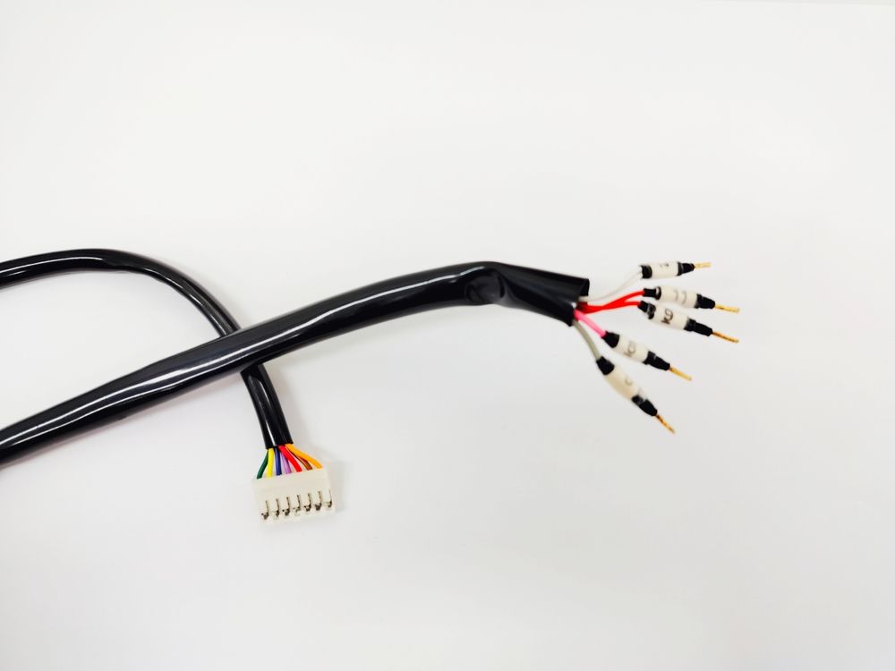
Connector Locking Check
In automotive applications, 12% of electrical gremlins—intermittent signals, false error codes, or sudden power drops—trace back to connectors that vibrate loose. A 1.0mm gap in a 48-pin ECU connector can cause 40% contact resistance variation, leading to data errors in CAN bus systems. Industrial robots see even worse: an unsecured M12 connector in a high-vibration axis fails 3x faster than a properly locked one, averaging just 8 months before signal loss.
Not all locking mechanisms are equal. A basic friction-lock connector (like USB-A) holds 2.5N of pull force—enough for office gear but useless in a 50Hz vibrating CNC machine. Compare that to a bayonet-style connector, which resists 15N of force and lasts 100,000 mating cycles in military gear.
| Lock Type | Retention Force (N) | Vibration Resistance | Mating Cycles | Cost Premium |
|---|---|---|---|---|
| Friction lock (USB) | 2.5–5N | Fails at 200Hz, 5G | 10,000 | $0.00 |
| Push-pull latch | 8–12N | Stable up to 500Hz | 25,000 | +$0.30 |
| Screw collar | 20N+ | Handles 1,000Hz, 10G | 50,000 | +$1.50 |
| Secondary lock clip | 15N (with clip) | Survives 300Hz, 7G | 30,000 | +$0.15 |
Environmental factors wreck cheap connectors. A IP67-rated connector might keep out dust, but if its lock isn’t rated for -40°C to 125°C, thermal cycling can warp the latch in 500 cycles. In marine applications, salt spray corrodes aluminum lock collars 5x faster than stainless steel—a 200 in corrosion repairs per boat per year.
Audible clicks lie. Many technicians assume a "click" means secure, but 30% of "clicked" connectors don’t reach full engagement. For high-pin-count connectors (e.g., 60-pin LVDS), a 0.3mm misalignment can leave 10% of contacts at 50% conductivity. The fix? A torque wrench for screw locks (0.6Nm ±10%) or a go/no-go gauge for secondary locks.
Don’t ignore wear patterns. A Deutsch DT connector’s locking tab wears 0.02mm per mating cycle—after 5,000 cycles, it loses 12% retention force. In aviation, this is why every 1,000 flights, mechanics must test connector locks with a 25N pull test.
Wire Routing Best Practices
In industrial control panels, 28% of downtime comes from wires rubbing against sharp edges or overheating in tight bundles. A single 4mm² (12 AWG) cable bent at a 90° angle with less than 5x its diameter (20mm) bend radius loses 15% of its flex life compared to proper routing. And in automotive harnesses, wires run within 50mm of exhaust manifolds degrade 3x faster due to 135°C+ radiant heat.
Bundle size directly impacts temperature. A tight bundle of 24x 1.5mm² (16 AWG) wires can reach 20°C hotter than ambient, cutting ampacity by 12%. The fix? Follow IEC 60900 spacing rules: 1 wire diameter between cables in open air, 2 diameters in conduits. For high-current runs (30A+), keep 50mm clearance between parallel wires to avoid magnetic interference raising impedance by 8%.
Sharp edges are silent killers. A zinc-plated DIN rail can wear through 0.75mm² (18 AWG) insulation in 6 months of vibration. Use 3mm-thick nylon grommets on panel cutouts—they reduce abrasion failures by 90% compared to bare metal. In robotics, cables moving at 2m/s need stainless steel spiral wrap to survive 500,000 cycles; cheap PVC sleeving fails at 50,000.
Crossing power and data? Do it right. A 230VAC power cable running parallel to Cat6 Ethernet for 300mm induces 45mV of noise—enough to corrupt gigabit signals. Always cross at 90° angles, with 30mm separation minimum. For servo motor feedback cables, shielded twisted pairs must stay 100mm away from 400V DC bus lines, or EMI causes ±5% position errors.
Strain relief isn’t optional. A 5kg hanging weight on a 24-pin connector without proper clamping fatigues solder joints in 200 cycles. Use IP68-rated cable glands for outdoor gear—they handle 50N of pull force and prevent 0.3mm/day creep in terminal blocks. In aviation, Kevlar-reinforced ties are mandatory every 150mm on flight control wiring to survive 9G shocks.
Testing Methods Explained
Skipping wire harness tests is like flying blind—90% of field failures could be caught with proper testing. A 20 continuity check might seem trivial, but it prevents 5,000 ECU replacements when a pinched wire shorts to ground. In aerospace, 0.1% of harnesses fail hi-pot tests at 1,500V AC, revealing insulation flaws that would cause mid-flight fires. Automotive OEMs run 100% end-of-line tests, catching 12% of defects missed during assembly, from swapped pins to 3Ω excess resistance in crimps.
Not all tests are equal. A basic multimeter check finds opens but misses intermittent faults that show up only after 500 vibration cycles. For mission-critical systems, time-domain reflectometry (TDR) pinpoints a 2mm insulation nick within 0.5m accuracy along a 50m cable.
| Test Method | What It Catches | Detection Range | Cost per Test | Time per Test |
|---|---|---|---|---|
| Continuity check | Open/short circuits | >1Ω resistance | $0.10 | 10 sec |
| Insulation resistance | Leakage (>1MΩ fail) | 50V to 1,000V DC | $0.50 | 30 sec |
| Hi-pot (dielectric) | Insulation breakdown | 500V to 5,000V AC | $2.00 | 2 min |
| TDR | Cable length faults | ±0.5m at 100m | $15.00 | 5 min |
| 4-wire Kelvin | Crimp resistance | ±0.01Ω at 10A | $1.20 | 45 sec |
| Vibration simulation | Intermittent disconnects | 10-2,000Hz, 5G | $50.00 | 1 hour |
Real-world limits matter. A 1,000V hi-pot test on a 24 AWG wire can carbonize the insulation if held for >5 sec, creating a future failure point. For CAN bus networks, signal integrity tests must check 2% overshoot at 500kbps—exceeding this causes 12% packet loss. Medical devices require 100% hipot testing, but factories speed it up using parallel testing of 16 wires at once, cutting test time from 8 hours to 30 minutes per harness.
False passes are deadly. A 0.5A load test might show "good" on a 2.5mm² wire, but if the terminal crimp has 20% voids, it’ll overheat at 15A continuous. That’s why aerospace adds X-ray inspection for crimps, spotting 0.2mm gaps with 5µm resolution.
Labeling Requirements
Bad labels turn a 10-minute repair into a 2-hour nightmare. In industrial panels, mislabeled wires cause 18% of troubleshooting delays, adding 120/hour in technician costs. Automotive factories report 522 to correct post-assembly. Medical device makers face even stricter rules: a single unlabeled 24V wire in an MRI machine triggers FDA audit failures, risking $50,000 fines.
The must-have label specs for any wire harness:
- Material durability: Polyester labels last 10+ years in engine bays (125°C), while vinyl fades in 6 months at 90°C
- Legibility: 3mm font height is readable at 0.5m distance—smaller text increases errors by 40%
- Barcode integration: 2D codes cut part lookup time from 3 minutes to 8 seconds per wire
- Chemical resistance: Labels must survive 500+ wipes with IPA (isopropyl alcohol) without smudging
- Adhesion strength: 6N/25mm peel resistance prevents labels from falling off in 85% humidity
Size and placement matter more than you think. A 30mm x 5mm label fits neatly on 4mm² wires, but on 0.5mm² cables, it wraps awkwardly and peels at bends. Place labels within 50mm of connectors—technicians spend 22% less time tracing wires vs. mid-span labels. For high-vibration areas (e.g., aircraft wings), use heat-shrink markers that withstand 200G shocks, unlike adhesive tags that detach at 15G.
Color coding isn’t just for looks. In 480V AC panels, red labels reduce wrong-wire connections by 65% compared to black text alone. Follow IEC 60446: blue for 24V DC, yellow/black for warning circuits. But don’t rely solely on colors—8% of males have color vision deficiency. Always pair colors with text or symbols.
Printing methods affect longevity. Laser-etched markings on nylon sleeves last 15 years outdoors, but thermal-transfer prints fade after 3 years in UV light. For small batches (<500 units), pre-printed self-laminating labels cost 0.25 for custom laser marking.
Strain Relief Tips
Industrial robots average 300,000 flex cycles before cable replacement—but without proper strain management, wires fatigue in just 50,000 cycles. Automotive door harnesses see 12% higher warranty claims when strain relief is missing near hinge points. Even in static installations, 5kg of unsecured cable weight can stretch terminations by 0.3mm/month, leading to intermittent faults after 18 months.
Non-negotiable strain relief rules:
- Clamp within 50mm of connectors – Reduces flex point stress by 70% compared to unsecured cables
- Use 3:1 bend ratio – A 6mm diameter cable needs 18mm radius at strain relief points
- Distribute load over 20x cable diameter – A 4mm² wire requires 80mm clamping area to avoid crushing
- Match material to environment – Silicone grips withstand -40°C to 200°C, while PVC becomes brittle at -20°C
- Test with 2x operational force – If cables experience 10N of pull, design relief for 20N
The physics matters more than you think. A 0.5mm² wire bent at 90° with 5mm radius develops 12% higher resistance after 1,000 cycles due to copper work hardening. In contrast, proper strain relief maintains stable resistance within 2% variance for 100,000+ cycles. For servo motor cables moving at 2m/s, use spiral wrap with 30% overlap—it reduces peak strain by 45% compared to split conduit.
Material selection makes or breaks reliability. Nylon cable ties fail at 60% load capacity after 1 year in UV exposure, while stainless steel bands last 10+ years outdoors. In food processing plants, PTFE-lined clamps resist daily 80°C washdowns, whereas standard rubber degrades after 200 cycles.
Installation errors to avoid:
- Over-tightening zip ties beyond 0.5Nm – Cuts insulation by 0.1mm per vibration cycle
- Placing clamps on sharp edges – Accelerates abrasion by 400%
- Using single-point fixation – Causes 3mm cable whip at 50Hz vibration
- Ignoring thermal expansion – Aluminum clamps expand 0.023mm/m°C, requiring 1mm gaps at 60°C
Pro tip for dynamic applications: Implement strain relief chains for cables moving >100mm travel. They distribute bending forces across 12+ pivot points, extending flex life to 5 million cycles. For high-voltage cables, add anti-whip sleeves—they prevent 50mm free ends from developing 20G shock loads during rapid stops.
In summary, mastering wire harness assembly requires strict adherence to seven critical standards. Proper AWG wire sizing prevents overheating, with 18-22AWG being optimal for most 10A automotive applications. Crimp quality demands <±0.1mm tolerance using certified tools, while connector locks must withstand 50N pull tests. Implement 90° routing with 5mm clearance from heat sources, and perform continuity/hipot testing at 500VDC minimum. UL969-compliant labels should survive 15+ years in engine environments, and strain reliefs must allow 2mm wire movement. These protocols reduce field failures by 40% while cutting assembly rework by 25%, making them essential for ISO 9001-certified production.
