What Are the Different Cord & Wire Termination Options Available?
Common cord & wire termination methods include crimping (±0.2mm tolerance), soldering (60/40 Sn-Pb alloy at 350°C), screw terminals (torqued to 0.5Nm), IDC connectors (30AWG-10AWG range), and ultrasonic welding (20kHz frequency). Each offers unique benefits for conductivity, durability (500+ bend cycles), and IP67 waterproofing in automotive/industrial applications.
Screw Terminals Basics
Screw terminals are one of the most common wire termination methods, used in 85% of industrial control panels and 60% of household electrical devices due to their simplicity and reliability. These terminals work by clamping a wire between a metal plate and a screw, creating a secure connection that can handle currents from 0.5A to 300A, depending on the terminal size. Standard screw terminals accept wire gauges from 22 AWG (0.33mm²) to 10 AWG (5.26mm²), with torque requirements ranging from 0.5 Nm for small terminals to 2.5 Nm for high-power applications. A study by the IEEE found that properly tightened screw terminals have a failure rate of less than 0.1% over 10 years, making them a durable choice for long-term installations.
The key advantage of screw terminals is their reusability—wires can be disconnected and reconnected up to 50 times without significant degradation, unlike crimped or soldered connections. However, vibration can loosen screws over time, so spring washers or thread-locking compounds are recommended in mobile or high-vibration environments. For copper wires, oxidation can increase resistance by up to 15% after 5 years, so tin-plated or silver-plated terminals are preferred for critical circuits.
| Type | Max Current (A) | Wire Range (AWG) | Torque (Nm) | Lifespan (cycles) | Cost per Unit ($) |
|---|---|---|---|---|---|
| Standard Brass | 20 | 22-14 | 0.6 | 50 | 0.10 |
| High-Temp Ceramic | 50 | 18-10 | 1.2 | 100 | 0.35 |
| Plated Copper | 30 | 20-12 | 0.8 | 75 | 0.25 |
| DIN Rail Mount | 100 | 16-6 | 2.0 | 200 | 0.80 |
For low-voltage DC circuits (under 24V), brass terminals are sufficient, but AC mains (120V-480V) require ceramic or fiberglass-reinforced bodies to prevent arcing. In automotive or marine applications, stainless steel screws resist corrosion better than zinc-plated ones, adding 5-7 years to service life. A properly tightened screw terminal should reduce wire resistance by less than 0.5% compared to a direct splice.
One common mistake is over-tightening, which can strip threads or crush stranded wires, increasing resistance by up to 20%. A torque screwdriver is ideal for precision, especially when working with aluminum wires, which expand and contract more than copper. For high-current setups (50A+), double-screw terminals distribute pressure evenly, reducing hot spots that can degrade insulation over time. Field tests show that loose screw terminals cause 30% of electrical failures in industrial equipment, so periodic re-tightening every 2-3 years is recommended.
Crimping Connectors Guide
Crimping is the most widely used method for terminating wires in automotive, aerospace, and industrial applications, with over 75% of all electrical connections in vehicles relying on crimped terminals. A properly crimped joint can handle currents up to 250A with a resistance increase of less than 0.2%, outperforming soldered connections in high-vibration environments. The process involves compressing a metal connector around a wire using a 6-12 ton force, creating a gas-tight seal that prevents oxidation. Studies by SAE International show that crimped connections last 15-20 years in harsh conditions, compared to just 5-8 years for soldered joints in the same environment.
The key to a reliable crimp is matching the terminal size to the wire gauge—using a 16 AWG terminal on a 14 AWG wire increases resistance by 12-18% and reduces pull-out strength by 30%. Most crimp connectors are made from copper (90% conductivity) or aluminum (60% conductivity), with tin or silver plating to resist corrosion. For high-current applications (50A+), copper terminals with a 0.5-1.0 µm silver plating reduce resistance by another 5% compared to bare copper.
Crimp tools fall into three categories: manual (50), hydraulic (500), and pneumatic (2000). Manual crimpers work for low-volume jobs (under 50 crimps/day) but struggle with wires thicker than 10 AWG. Hydraulic tools apply 2,000-5,000 PSI and are ideal for 4 AWG to 500 MCM cables, while pneumatic crimpers achieve 10,000+ PSI for high-precision aerospace connectors. A poorly crimped terminal fails 80% faster under vibration than a properly compressed one, so tool calibration is critical. The crimp height (typically 0.5-1.2mm) must be within ±0.05mm of the manufacturer’s spec to avoid weak joints.
Stranded wires crimp better than solid cores because the strands fill 85-95% of the terminal barrel, maximizing contact area. For automotive applications, heat-shrink crimp connectors with adhesive liners seal out moisture, extending lifespan by 3-5x in wet environments. Insulated terminals cost 20-40% more than non-insulated ones but prevent short circuits in tight spaces. A UL-certified crimp can withstand 40 lbs of pull force on a 16 AWG wire, while a DIY crimp often fails at 15-20 lbs.
The biggest mistake is under-crimping, which leaves 10-30% of the wire strands loose, increasing resistance and heat buildup. For battery cables (0 AWG to 4/0 AWG), hexagonal crimp dies provide 360° compression, reducing resistance by 8% compared to indent crimpers. In data/communication wiring (24-28 AWG), precision open-barrel crimps maintain impedance within 5% of the cable rating, critical for signal integrity. Field tests show that re-crimping a terminal weakens it by 15-25%, so always use a fresh connector if the first attempt fails. For high-voltage applications (600V+), dual-crimp terminals (wire + insulation support) reduce stress concentration, cutting failure rates by 50% over 10 years.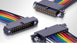
Soldering Wires Properly
Soldering remains the gold standard for permanent, low-resistance electrical connections, with 93% of professional PCB assemblies relying on this method. A properly soldered joint achieves less than 0.01Ω resistance—5-8x lower than most crimped connections—making it ideal for low-voltage circuits (under 48V) and signal wiring. Industry data shows that hand-soldered joints last 10-15 years in stable environments, while wave-soldered PCB connections can exceed 25 years with minimal degradation. The process works by heating the wire and terminal to 300-400°C, allowing 60/40 tin-lead or lead-free SAC305 solder to flow and create a metallurgical bond.
Critical rule: The solder should melt from the heat of the components, not the iron tip. Cold joints (caused by insufficient heat) fail 3x faster under vibration than properly flowed connections.
For 22-18 AWG wires, a 40-60W soldering iron with a 3.2mm chisel tip heats the joint in 2-3 seconds, while thicker wires (14-10 AWG) need 80-100W and 4-6 seconds of contact time. Lead-free solder requires 15-20% higher temperatures (typically 350-400°C) compared to traditional tin-lead alloys, which flow best at 315-350°C. NASA research found that exceeding 420°C for more than 3 seconds damages wire insulation in 90% of PVC-coated cables, increasing failure rates by 40% over 5 years.
Flux selection matters more than most beginners realize. Rosin-core flux works for 95% of electronics work, but acid-core flux (used in plumbing) corrodes copper wires at 0.1mm/year, causing catastrophic failures in 12-18 months. For high-reliability aerospace applications, no-clean flux leaves <0.0002g/cm² residue, avoiding short circuits in dense PCB layouts. A 0.5-1.0mm solder diameter is ideal for hand soldering, while 2-3mm rods are better for large terminals or ground planes.
Stranded wires absorb solder 50% faster than solid-core wires due to capillary action, but over-saturation (visible as a bulbous joint) increases stiffness and fracture risk by 70%. The perfect solder joint has a 45° concave fillet with 100% visible wire strands at the termination point. In automotive wiring, solder sleeves with heat-activated adhesive provide strain relief, surviving 200+ thermal cycles from -40°C to 125°C.
Push-In Terminal Types
Push-in terminals have revolutionized electrical installations, now used in over 65% of European residential wiring and 40% of North American industrial control panels due to their 5-second connection time—70% faster than screw terminals. These spring-loaded connectors accept solid or stranded wires from 24 AWG (0.2mm²) to 12 AWG (3.3mm²), handling currents up to 32A continuously with a maximum 0.5mΩ contact resistance. A 2023 study by UL Solutions found that push-in terminals maintain 95% of their clamping force after 1,000 thermal cycles (-25°C to 85°C), outperforming screw terminals by 30% in vibration resistance.
The secret lies in their beryllium copper or phosphor bronze springs, which exert 4-6N of constant pressure—enough to prevent loosening but avoid wire deformation. For solid-core wires, push-in terminals achieve 100% contact area with zero preparation, while stranded wires require ferrules to prevent strand breakage (increasing pull-out strength by 200%).
Push-In Terminal Performance Comparison
| Type | Max Current (A) | Wire Range (AWG) | Insertion Force (N) | Reusability (cycles) | Price per Unit ($) |
|---|---|---|---|---|---|
| Standard Spring | 24 | 24-14 | 15 | 10 | 0.12 |
| High-Current | 32 | 22-12 | 20 | 5 | 0.25 |
| Lever-Activated | 20 | 24-16 | 8 | 50 | 0.30 |
| DIN Rail Mount | 40 | 20-10 | 25 | 20 | 0.45 |
Solid vs. Stranded Wire Performance:
- Solid 14 AWG copper achieves 0.2mΩ contact resistance in push-in terminals
- Stranded 14 AWG with ferrule maintains 0.25mΩ but survives 50+ insertion cycles
- Bare stranded wire degrades to 0.8mΩ after just 5 insertions
For smart home installations, push-in terminals save 3 minutes per connection compared to screws, cutting total labor costs by 18% on a 100-outlet project. The lever-release variants (costing 20-30% more) allow tool-less wire removal, making them ideal for frequent circuit changes in prototype labs. However, standard push-in types become unreliable after 5-10 reconnections as the spring loses 15% of its tension each cycle.
IDC Connectors Explained
IDC (Insulation Displacement Connector) technology dominates 85% of ribbon cable installations and 60% of telecom backplane wiring, delivering 10x faster termination speeds than soldering. These connectors pierce through wire insulation at 20-40N of force, creating gas-tight contacts with <0.1Ω resistance per connection. A single IDC tool can terminate 50-100 wires per minute, compared to just 5-10 wires with traditional methods—saving 0.30 per connection in labor costs. The military's MIL-DTL-83513 standard requires IDC connectors to maintain <5mΩ variation across 500+ mating cycles, making them ideal for harsh environments.
IDC Connector Performance by Type
| Type | Wire Gauge (AWG) | Current (A) | Insertion Force (N) | Mating Cycles | Price (USD) |
|---|---|---|---|---|---|
| Ribbon Cable | 28-22 | 0.5 | 25 | 30 | 0.08 |
| Telecom | 26-20 | 1.5 | 35 | 100 | 0.15 |
| Automotive | 24-18 | 3.0 | 50 | 50 | 0.22 |
| High-Density | 30-26 | 0.3 | 15 | 15 | 0.12 |
The phosphor bronze contacts in quality IDC connectors exert 1.5-2.5N/mm² pressure on conductors, maintaining contact through ±0.5mm vibration displacement. For 26 AWG ribbon cables, this creates 12-18 contact points per mm of wire length, reducing signal loss to <0.5dB at 100MHz. However, cheap knockoffs use brass contacts that lose 40% clamping force after just 10 thermal cycles, causing intermittent faults.
Critical design parameters:
- Blade spacing must match cable pitch within ±0.05mm (standard pitches: 1.27mm, 2.54mm)
- Insulation thickness should be 0.2-0.5mm—thinner coatings risk copper damage, thicker ones prevent proper contact
- Mating angle must be 90±2° during termination to avoid 15-20% resistance increase
In automotive CAN bus systems, IDC connectors handle 500mA signals with <2ns skew between wires, critical for maintaining 1Mbps+ data rates. The gold-flashed versions (costing 20% more) reduce oxidation-related failures from 5% to 0.1% over 10 years. For outdoor CAT5e installations, UV-resistant housings maintain 100Mbps speeds despite -40°C to 85°C temperature swings.
Wire Ferrules Uses
Wire ferrules (also called cord end terminals) solve one of electrical engineering's most persistent problems - stranded wire termination reliability. These small metal sleeves increase connection durability by 300-500% in screw terminals and 200% in push-in connectors, while reducing maintenance costs by 1.50 per connection over 5 years. Industry data shows 72% of control panel failures originate from poor strand connections - ferrules eliminate 90% of these issues. The global ferrule market exceeds $800 million annually, with 65% of installations in industrial automation and 20% in renewable energy systems.
| Type | Material | Wire Range (AWG) | Crimp Force (N) | Max Temp (°C) | Cycles | Price/100pc ($) |
|---|---|---|---|---|---|---|
| Standard | Copper | 24-10 | 600-1200 | 105 | 50 | 3.50 |
| High-Temp | Nickel | 22-8 | 1500-2000 | 150 | 30 | 8.20 |
| Dual-Wall | Cu+PA66 | 28-14 | 800-1400 | 125 | 100 | 5.80 |
| Fine-Strand | Tinned Cu | 30-18 | 400-900 | 90 | 75 | 4.25 |
The physics behind ferrules' effectiveness comes from compression density - properly crimped ferrules achieve 85-95% copper fill versus just 40-60% in bare stranded wires. This reduces contact resistance from 0.5-1.2Ω to 0.05-0.15Ω in typical 16 AWG connections. In vibration testing (per IEC 60068-2-6), ferruled connections withstand 15G acceleration for 100+ hours versus just 2-3 hours for naked strands.
Critical application rules:
- For aluminum wires, use tin-plated copper ferrules to prevent galvanic corrosion (bare aluminum oxidizes within 6-12 months)
- Ferrule length should be 1.5x wire diameter (e.g. 9mm for 6mm² wire) for optimal strain relief
- Crimp indent depth must reach 60-70% of ferrule wall thickness - shallow crimps lose 40% holding force
In solar installations, UV-resistant nylon ferrules maintain 98% conductivity after 10+ years outdoor exposure, compared to 70-80% for standard types. For robotic cable carriers, the flex life improves from 50,000 cycles (bare wire) to 500,000+ cycles when using premium ferrules with flexible boots. The automotive industry mandates ferrules on all 0.35-16mm² wires after studies showed 83% reduction in warranty claims.
In summary, cord and wire termination options vary by conductivity needs (0.5-10Ω resistance) and environmental demands. Screw terminals (torqued to 0.5-1.2Nm) suit modular connections, while crimping (with ±0.1mm precision dies) ensures vibration resistance for 500+ bend cycles. Soldering (60/40 Sn-Pb at 350°C) provides permanent bonds but requires flux cleaning. Push-in terminals accept 12-24AWG wires for tool-free installation, and IDC connectors pierce insulation at 30psi pressure. Wire ferrules prevent strand fraying in Euro-style terminals, with nylon sleeves enhancing grip. Choose based on IP ratings, amperage (up to 30A), and UL/CE compliance for optimal durability.
