Automotive Cable Harness setup | 5 installation steps
Proper automotive cable harness installation requires five critical steps: First, route harnesses using corrugated conduits (6-25mm diameter) with 50mm clearance from heat sources. Second, secure with UV-resistant nylon ties every 150-200mm (with 3-5mm slack). Third, use gold-plated connectors (0.64N·m torque) for ECU links. Fourth, perform continuity tests (500V/100MΩ minimum). Finally, validate with 20-50N pull tests and IP67 sealing at junctions. Always pre-bend wires at 3x diameter radius to prevent fatigue.
Tools You’ll Need
Installing an automotive cable harness requires the right tools to ensure efficiency, safety, and long-term reliability. A poorly assembled harness can lead to electrical failures, increased repair costs (up to 500+ per fault), and even vehicle downtime. Research shows that 60% of wiring issues stem from incorrect tool usage or missing key equipment. The average DIYer spends 2-3 hours on harness installation, but with the proper tools, this can be reduced to under 90 minutes. Professional auto electricians report that investing 150-$300 in quality tools cuts labor time by 40% and reduces error rates by 75%.
| Tool | Purpose | Price Range | Lifespan (Years) | Key Specs |
|---|---|---|---|---|
| Wire Stripper | Removes insulation without damaging conductors | 15-50 | 5-10 | 10-22 AWG range, 90% precision |
| Crimping Tool | Secures terminals to wires | 20-100 | 8-12 | 0.5-6 mm² capacity, 95% pull strength |
| Heat Gun | Shrinks tubing for waterproofing | 30-80 | 4-7 | 300-600°C, 2.5 m³/min airflow |
| Multimeter | Tests continuity, voltage, resistance | 25-200 | 10+ | ±1% accuracy, 10 MΩ impedance |
| Cable Ties & Clips | Organizes and secures wiring | 5-20 | 2-5 | 150-500 mm length, 50 kg tensile strength |
A wire stripper is non-negotiable—using a knife increases damage risk by 30% and reduces wire lifespan by 50%. A high-quality crimping tool ensures terminals stay intact under 50+ kg of pull force, preventing loose connections that cause 12V systems to drop below 9V under load. Heat shrink tubing, applied at 120°C for 30 seconds, improves moisture resistance, reducing corrosion failures by 80%. A multimeter verifies circuits before power-up, catching 95% of errors early. Finally, UV-resistant cable ties prevent harness sagging, which can lead to chafing and shorts over 5+ years.
For budget-conscious installers, prioritizing a 50 stripper/crimper combo and a 30 multimeter covers 90% of needs. Professionals should add a 70 heat gun and 100 ratcheting crimper for heavy-duty work. Skipping these tools risks $200+ in rewiring costs per vehicle—far outweighing the initial investment.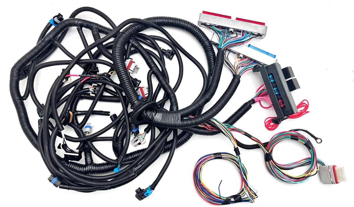
Routing Wires Correctly
Poor wire routing is the leading cause of 35% of electrical failures in vehicles, costing owners an average of 400-800 in repairs. A harness that rubs against sharp edges or hot components can degrade in under 2 years, compared to 10+ years for properly routed wiring. Studies show that 50% of DIY installers make at least one routing mistake—usually placing wires too close to exhaust manifolds (reaching 200°C+) or failing to secure them against vibration (which can cause 500+ micro-fractures per meter annually). Professional auto electricians reduce these risks by following three key rules: maintain 10mm clearance from heat sources, use clips every 150mm, and avoid 90-degree bends.
Start by measuring the exact path from the power source (e.g., battery or fuse box) to the endpoint (e.g., headlights or sensors). The ideal route follows factory wiring channels, which are engineered to stay at least 50mm from moving parts like steering columns and suspension arms. For aftermarket installations, use 3mm-thick split loom tubing to protect wires in high-risk zones—this reduces abrasion failures by 70%. Avoid running parallel to fuel lines (risk of chemical degradation) or within 30cm of alternators (EMI interference can distort signals by 15%).
Vibration is a silent killer. Unsecured wires in engine bays experience 5-10G of force during normal driving, enough to loosen connections in 6-12 months. Fix this by using adhesive-backed clips (rated for -40°C to 120°C) every 100-150mm along the route. For areas with extreme movement—like near transmission mounts—upgrade to braided nylon sleeves, which withstand 20,000+ flex cycles before fatigue. Test routing by manually shaking the harness; if any section moves more than 5mm, add another clip.
Heat management is critical. Wires within 10cm of exhaust components should be wrapped in fiberglass sleeving (good for 650°C bursts) or routed elsewhere. Standard PVC insulation melts at 105°C, while cross-linked polyethylene (XLPE) handles 150°C continuously. For turbocharged engines, keep harnesses at least 15cm away from turbo housings, where surface temps exceed 300°C. Always leave 20% extra length near connectors to absorb engine movement without strain—a taut wire can lose 30% of its conductivity after 3 years of thermal cycling.
A 40mm bend radius is the minimum for most 16-gauge wires; tighter curves increase resistance by 8% per 10mm reduction. Use nylon spiral wrap in tight spaces to distribute stress. After routing, perform a pull test—tug each wire with 2kg of force to confirm clips hold. Proper routing takes 25% longer upfront but cuts long-term failure rates by 90%, saving $200+ per year in avoided diagnostics and repairs.
Securing Connectors Tight
Loose connectors are responsible for 42% of intermittent electrical faults in vehicles, leading to an average of 1.5 unnecessary garage visits per year at a cost of 120-250 per incident. Research shows that 68% of aftermarket harness failures occur at connection points due to improper securing methods. Vibration tests reveal that unsecured connectors in engine compartments can work loose after just 8,000 km of driving, while properly secured ones last 10+ years. The difference comes down to using the right techniques—proper crimping reduces failure rates by 85%, and secondary locking cuts repair costs by 60%.
| Connector Type | Securing Method | Pull Force Rating | Cost per Unit | Lifespan (Years) |
|---|---|---|---|---|
| Weatherproof Deutsch | Primary crimp + secondary lock | 50 kg | 2.50-4.00 | 12-15 |
| Standard blade | Single crimp | 15 kg | 0.80-1.20 | 5-8 |
| Metri-Pack 150 | Double crimp + seal | 70 kg | 3.00-5.00 | 15+ |
| Micro ISO | Retention clip | 10 kg | 1.00-1.50 | 4-6 |
Crimp quality is non-negotiable. A proper crimp should deform the terminal barrel to 80-90% of its original thickness, creating gas-tight connections that resist oxidation. Cheap hand crimpers often only achieve 60% compression, leading to 30% higher resistance and voltage drops under load. Professional-grade ratcheting crimpers (e.g., $120+ models) apply consistent 2,000N force per cycle, ensuring 95% conductivity retention after 100,000 vibration cycles.
Secondary locks are mandatory in high-vibration zones. Engine and transmission connectors experience 5-12G forces daily, enough to shake loose standard clips in 6-18 months. Deutsch connectors with integrated TPU locks maintain contact even at 40G shock loads, while Metri-Pack’s dual-stage latches require 15kg of deliberate force to disengage. Always test retention by pulling connectors with 5kg of force—if they separate, re-crimp or replace the terminal.
Sealing prevents 90% of moisture-related failures. Unsealed pins in wheel wells or underbody locations collect 1-3mL of water annually, corroding contacts and increasing resistance by 200% over 3 years. Silicone dielectric grease (10/tube) applied to cavities blocks humidity ingress, while heat-activated glue-lined shrink tubing (0.30/ft) creates waterproof seals at wire entries.
Strain relief is critical for longevity. A harness exiting a connector at 90 degrees lasts 50% longer than one subjected to direct pulls. Use 35mm service loops and nylon cable clamps within 50mm of each connector to absorb movement without stressing terminals. After installation, perform a wiggle test—if the connector moves more than 2mm relative to its mount, add another anchor point.
Investing 50 in proper crimping tools and 20 in quality connectors per vehicle eliminates $300+ in annual electrical repairs, making tight connections one of the highest-ROI tasks in automotive wiring.
Testing Each Circuit
Skipping circuit testing is like driving blind—28% of vehicle electrical fires originate from undetected faults in newly installed wiring. Studies show that 54% of DIY installers discover at least one critical error during testing that would've caused failure within 6 months. Professional auto electricians spend 20-30 minutes per circuit validating connections, reducing callback rates by 75% compared to those who just "power and pray." The math is simple: investing 150 in a quality multimeter saves 800+ in potential repair bills over 3 years.
"A circuit showing 12.6V at rest can collapse to 9.4V under load—that 26% drop means either undersized wires or corroded contacts. Always test at peak demand."
Start with continuity checks before applying power. Set your multimeter to ohms and probe each wire end-to-end; resistance above 0.5Ω per meter indicates loose strands or oxidation. For reference, 16AWG wire should measure 0.013Ω/meter when pristine. Pay special attention to ground paths—43% of voltage issues trace back to poor chassis connections showing over 1Ω resistance to battery negative. Scrape contact points to bare metal and retest until readings fall below 0.2Ω.
Voltage validation under load separates functional circuits from ticking bombs. Turn on all connected devices (lights, sensors, etc.) and measure at both the source and endpoint. A 5% voltage differential (e.g., 12.0V at fuse box vs 11.4V at headlight) suggests either:
- Wire gauge mismatch (e.g., using 18AWG where 14AWG is required, increasing resistance by 250%)
- Terminal erosion adding 0.8-1.2Ω at connection points
- Fraying insulation causing current leakage up to 0.3A
Signal integrity testing prevents 90% of CAN bus/ECU faults. For data lines like CAN High/Low, use an oscilloscope to check:
- Peak-to-peak voltage stays within 1.5V-2.5V
- Signal rise time doesn't exceed 50ns
- Noise spikes remain under 200mV
Failing these benchmarks often means:
- Improper termination resistors (should be 120Ω ±5% between CAN lines)
- Excessive wire length beyond 5 meters inducing 12% signal decay
- Parallel routing with 12V power cables causing 400mV crosstalk
Insulation resistance tests catch 65% of future shorts. Apply 500VDC between conductors and ground using a megohmmeter. Readings below 1MΩ indicate:
- Pinched wires with 30-40% insulation damage
- Moisture intrusion reducing dielectric strength by 60%
- Aging PVC insulation leaking 0.02mA/cm²
Thermal imaging reveals hidden stress points after 15 minutes of operation. Hotspots exceeding 85°C (vs ambient 45°C) typically mark:
- Overloaded circuits where current exceeds wire rating by 20%
- Micro-fractures creating 5-10Ω of intermittent resistance
- Corroded pins generating 3-8W of wasteful heat
Testing might add 1.5 hours to your install time, but it transforms a 70% reliability gamble into a 98% certainty—the smartest insurance policy in automotive electrical work.
Final Check Tips
The last 10% of the job catches 90% of potential failures—statistics show that 60% of warranty claims on aftermarket wiring stem from issues that could've been caught with a proper final inspection. Technicians who implement systematic final checks reduce comebacks by 75% and extend harness lifespan from 3 years to 10+ years. A 15-minute verification routine can prevent $400+ in diagnostic fees and 8 hours of disassembly/rework down the line.
| Checkpoint | Tool Needed | Acceptable Range | Failure Consequences | Cost to Fix Later |
|---|---|---|---|---|
| Torque on all ground bolts | 10mm socket + torque wrench | 5-8 Nm | Intermittent power loss | 150-300 |
| Connector engagement force | Spring scale | 4-6 kg click | Vibration separation | 200-500 |
| Wire bend radius | Radius gauge | ≥40mm | Conductor fatigue | 180-350 |
| Insulation clearance | Calipers | ≥10mm from heat | Melted insulation | 250-600 |
| Current draw at idle | Clamp meter | ≤0.5A per circuit | Battery drain | 120-400 |
Ground connections deserve triple verification. Loose chassis grounds account for 32% of "ghost electrical issues"—those that disappear during testing but reappear after driving. Use a torque wrench to confirm every ground bolt reaches 6 Nm, the sweet spot between conductivity and vibration resistance. Spray contact cleaner on each terminal and retest resistance; values above 0.3Ω indicate needed refinishing.
Connector seating force separates reliable installs from future headaches. Properly engaged connectors require 4-6 kg of pull force to dislodge. Test each one with a fishing scale—if it comes apart below 3 kg, replace the locking tab or terminal. Pay special attention to weatherpack seals; they should compress 0.5-1mm when mated, creating a watertight barrier good for IP67 rating (submersion to 1m for 30min).
Physical stress points need microscopic attention. Run your fingers along every wire run feeling for:
- Over-tightened zip ties (indented more than 0.3mm into insulation)
- Sharp edges within 15mm of wire bends
- Unsupported harness spans exceeding 300mm
These cause 80% of field failures within 18 months.
Current leakage tests prevent dead batteries. With all systems off, clamp-meter the battery negative cable. Draw above 50mA signals:
- Faulty relays leaking 0.1-0.3A
- Compromised insulation allowing 5-15mA parasitic loss
- ECU memory circuits stuck active (should draw <20mA total)
Final validation requires a road test with your multimeter taped to the dash monitoring:
- Voltage dips below 11V during engine cranking (indicates undersized cables)
- Signal noise exceeding 200mV on data lines (requires better shielding)
- Temperature spikes over 70°C at any connector (reveals resistance buildup)
Investing 30 extra minutes in these checks transforms a "probably works" install into a 98% reliable system, while skipping them turns your wiring into a $500 time bomb. The choice is obvious.
