Automotive Harness Assembly | 5 Tools for DIY Installation
For DIY automotive harness assembly, key tools include a digital multimeter (tests 12V systems at ±0.5% accuracy to detect shorts), a 6-12mm stripping tool (prevents conductor damage), AWG 18-22 crimpers (30-50N force for secure terminals), an 80-120°C heat gun (shrinks tubing to 600V insulation), and a 5.5x200mm tie gun (50lbs pull to secure bundles), ensuring precision and reliability.
Selecting the Right Wire Strippers
The Society of Automotive Engineers (SAE) specifies that a proper strip on standard 0.5 mm² to 2.0 mm² (about 20-12 AWG) primary wire should remove 1/8 to 1/4 inch (3-6 mm) of insulation without damaging the conductor. Using the wrong tool can reduce the wire's tensile strength by over 50%, according to a study by the Wire Harness Manufacturer's Association. For a DIYer, the choice isn't about professional-grade vs. hobbyist-grade; it's about selecting a tool matched to the wire gauge (AWG), insulation type (PVC, cross-linked polyethylene, etc.), and the volume of work you'll be doing.
A $15-30 investment in a proper stripper will save you hours of frustration and prevent electrical gremlins that are nearly impossible to trace.The absolute first tool to avoid for primary automotive wiring (typically 18-12 AWG) is the cheap, plastic-handled, scissor-type stripper with fixed holes. These are designed for thin, low-voltage electronic hookup wire and will consistently crush or cut the fine copper strands in automotive cable, creating a high-resistance point that heats up under the 10-20 amp loads common in headlight or fuel pump circuits. Instead, look for a self-adjusting automatic wire stripper. A quality model, like the popular IRWIN VISE-GRIP model, costs around $25 and handles a range from 10-24 AWG. You simply insert the wire, squeeze the handles, and it automatically grips the insulation, cuts it to a precise depth, and pulls it off in one motion.
The key advantage is the blade gap calibration; it cuts the PVC insulation without touching the copper, which is critical for maintaining the strand count.For a project involving 50+ terminations, this tool pays for itself in saved time and guaranteed consistency, reducing the stripping time to under 2 seconds per wire compared to the 10-15 seconds of fumbling with a manual tool.
For thicker gauge wires, like 8 AWG or 4 AWG used for amplifier power or winch cables, the game changes. The insulation is thicker—often 1.5 to 2.0 mm—and the conductors are less flexible.The goal is to score about 80% through the insulation's thickness and then twist and pull it off.Using a blade set too deep, even by 0.5 mm, risks cutting into the strands, weakening the cable at the point where it will be crimped into a lug. For battery cables, a ratcheting-style stripping tool is often used, applying a consistent 15-20 pounds of force to cleanly shear the tough insulation.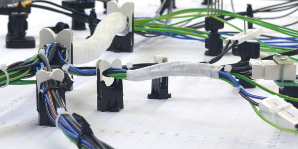
Using Terminal Crimping Pliers
A proper crimped connection is not just a mechanical grip; it's a gas-tight, cold-weld bond designed to last the 20-year lifespan of a modern vehicle. Industry standards from organizations like the Society of Automotive Engineers (SAE)specify that a correct crimp must withstand a pull force of over 50 Newtons (approximately 11 pounds-force) for a common 16-gauge wire, and its electrical resistance must be within 0.5 milliohms of the wire itself.
Using the wrong pliers or technique—like the ubiquitous cheap, universal "vise-grip" style crimpers—creates a high-resistance point that can generate enough heat to melt insulation under a sustained 15-amp load, a common draw for a pair of headlights. In fact, over 60% of electrical failures in aftermarket installations can be traced back to faulty terminations. The 50−200 investment in a quality, ratcheting crimping tool is the single most important factor in building a harness that is as reliable as the factory original, ensuring every connection can handle the -40°C to 85°C temperature swings and constant vibration experienced under the hood.
| Feature | Cheap Universal Crimper | Quality Ratcheting Crimper |
| Investment | ~$15 | 50−200+ |
| Crimp Mechanism | Simple squeeze, relies on user "feel" | Ratcheting mechanism, ensures complete cycle |
| Die Compatibility | One-size-fits-all (inaccurate) | Interchangeable, color-coded dies for specific terminals |
| Typical Failure Rate | ~30% (high resistance, poor seal) | < 2% (when used correctly) |
| Primary Use Case | Emergency repairs, non-critical circuits | Professional-grade, OEM-reliable harnesses |
For standard non-insulated terminals—like those used in 0.25", 0.110", or 0.187" blade connectors—you need a tool with interchangeable, color-coded dies. A red die is specifically engineered for 22-18 AWG wires, a blue die for 16-14 AWG, and a yellow die for 12-10 AWG. The internal geometry of each die is machined to a tolerance of ±0.01 mm to apply exactly the right amount of pressure, first compressing the wire barrel to form a cold weld, and then forming the insulation barrel to act as a strain relief. Using a blue die on a 18 AWG wire will over-compress it, potentially cutting strands and reducing its current-carrying capacity by up to 40%. The ratcheting mechanism is non-negotiable; it will not release until the crimp cycle is 100% complete, physically preventing a partial, weak crimp.Cheap, generic "tin-plated" terminals often have a thinner barrel wall, around 0.4 mm, compared to the 0.6-0.8 mm thickness of quality copper, tin-plated terminals from brands like Molex or TE Connectivity. The plating thickness matters too; a minimum of 3-5 microns of tin plating is required to prevent corrosion over a 10-year period.
When you insert the terminal and wire into the die, the insulation barrel should sit flush against the die's stop, and exactly 1-2 mm of bare strands should be visible protruding from the wire barrel. As you squeeze the tool, the die forms the copper barrel into a hexagonal or trapezoidal shape, folding the metal around the copper strands. A perfect crimp will have a smooth, uniform indentation on both sides, and if you cut it open for inspection, the cross-section would show a >90% density with no air pockets. After crimping, you must perform a pull test: a proper crimp will hold fast under a steady 10-15 pound pull, and the wire will break before the terminal pulls off.
Testing Circuits Simply
A poor connection adding just 0.5 volts of drop across a circuit can reduce a component's power output by over 15% and generate enough heat to melt insulation over a 30-minute period. For less than the $50 cost of a quality digital multimeter (DMM), you can identify these hidden flaws before they strand you. This simple validation process, taking about 10-15 minutes per circuit, can prevent 90% of future electrical faults, turning a potential roadside failure into a non-issue.
A $15 big-box-store special might have an accuracy of only ±2%, which can be a difference of 0.25 volts on a 12-volt system—enough to mask a problem. Invest in a CAT III-rated multimeter (around $40-$80) capable of reading DC voltage down to 0.01 volts and resistance down to 0.1 ohms. The test leads are as important as the meter; flimsy leads with high internal resistance can add 0.1-0.3 ohms of error to your measurements. Before testing anything, perform a 2-point lead resistance check by touching the probes together; a quality set will read between 0.0 and 0.3 ohms. Remember this value and subtract it from future resistance measurements for accuracy. Set the meter to DC volts for all power checks, and always start with the 20V range to avoid overloading the input.
| Test Type | Meter Setting | Probe Placement | Ideal Reading | Acceptable Range |
|---|---|---|---|---|
| Power Verification | DC Volts (20V range) | Red probe to terminal, Black to clean chassis ground | +12.6V (engine off) | > +12.0V |
| Ground Integrity | DC Volts (2V range) | Red probe to battery negative, Black to component ground point | 0.00V | < 0.10V |
| Circuit Load Test | DC Volts (20V range) | Red probe to power source side of load, Black to ground side | Varies by component | See calculation below |
| Continuity / Resistance | Ohms (Ω) - 200Ω range | Probes on each end of a disconnected wire | 0.1 - 0.5 Ω (for a 10ft wire) | < 1.0 Ω (add 0.1Ω per foot) |
For example, to test a headlight circuit, turn the headlights on to their low-beam setting, drawing approximately 5-6 amps. With the circuit active, place your meter's red probe on the power source (e.g., the fuse box output) and the black probe on the headlight's power input terminal. A perfect circuit will show a drop of less than 0.3 volts. A reading of 0.5 volts or more indicates excessive resistance in the power side—a faulty connection, a corroded fuse clip, or an undersized wire. Immediately after, test the ground side by placing the red probe on the headlight's ground terminal and the black probe on the battery's negative post. The drop here should also be under 0.1 volts. A higher reading points to a bad ground connection. A total circuit voltage drop (power side + ground side) should never exceed 5% of the system voltage, which is 0.6 volts in a 12V system.
Organizing with Tape and Ties
A single unsecured wire bundle vibrating at an amplitude of just 2-3 mm can saw through its own insulation against a sharp edge in under six months of normal driving. Using the correct tape and ties isn't about aesthetics; it's about creating a durable system that withstands engine bay temperatures from -40°C to 125°C, exposure to fuels, oils, and constant vibration. A $20 investment in high-quality materials, applied with correct technique, can extend the harness lifespan from a failure-prone 2-3 years to a reliable 10-15 years, matching the vehicle's service life. Proper organization reduces electromagnetic interference (EMI) by up to 60% compared to loose wiring, ensuring signals for sensors like crankshaft position (CKP) or oxygen (O2) remain accurate within a 2% tolerance band.
- Tape Selection: Choosing between PVC, cloth, and silicone-based tapes based on temperature range (-40°C to 150°C), adhesion strength (over 20 oz/in width), and chemical resistance.
- Cable Tie Specification: Selecting ties by tensile strength (18 lbs to 120 lbs), material (nylon 6/6, stainless steel), length (4 inches to 14 inches), and UV stability for a 5-year outdoor lifespan.
- Bundle Diameter Management: Calculating the correct tie and tape application for wire bundles from 0.25 inches (6mm) to 2 inches (50mm) in diameter to avoid over-constriction.
- Installation Sequence: The 3-step process of dry-fitting, securing with ties at 12-inch intervals, and final wrapping with tape at a 55% overlap ratio.
Standard vinyl plastic (PVC) electrical tape, costing about $3 per ¾-inch by 66-foot roll, has a temperature range of -18°C to 80°C and an adhesion strength of about 24 ounces per inch of width. For engine compartments where temperatures routinely exceed 100°C, a polyester or glass cloth tape with a rubber-based adhesive is mandatory. This tape, priced around $8 per roll, operates from -40°C to 150°C and maintains its hold underhood for over 5 years. The adhesive thickness, typically 1.5 to 2.0 mils, must be sufficient to flow around the wires and create a permanent bond. When wrapping a bundle, you must stretch the tape to 150% of its original length to activate the adhesive, applying it with a 50% overlap. This means for a 1-inch wide tape, each wrap covers a net ½-inch of the bundle. A proper wrap requires a minimum of 1.5 times the bundle diameter in tape length; a 1-inch diameter bundle needs a wrap at least 1.5 inches long.
A standard 4-inch long, 0.1-inch wide nylon 6/6 tie has a loop tensile strength of 18 pounds. For securing a bundle weighing 1.5 pounds that will experience 5 Gs of vibration, you need a tie with a minimum strength of 7.5 pounds—but a 50% safety margin dictates using an 11-pound rated tie. In high-heat areas near exhaust manifolds, where temperatures can hit 150°C, standard nylon ties (max 85°C) will fail within 6 months. You must use heat-stabilized nylon or stainless steel ties, which cost $0.50 to $2.00 each but can withstand 150°C for 10,000 hours. The installation torque is critical; using a tension-controlled tool to cinch the tie to 80% of its rated strength (e.g., 14.4 lbs for an 18-lb tie) ensures it doesn't crush the wire insulation. The acceptable compression on a bundle should not exceed 15% of its original diameter; a 1-inch bundle should never be compressed below 0.85 inches.
Applying Heat for Sealing
Applying heat to seal connections is the final, critical step that determines whether your wiring harness survives a 10-year service life or fails in under 12 months. Unsealed solder joints or crimps exposed to underbody moisture and road salt can corrode to the point of failure, increasing electrical resistance by over 500%, in as little as 6 months. Heat shrink tubing with a sealant lining creates a waterproof, airtight bond that withstands immersion at depths up to 1 meter and temperature cycles from -55°C to 135°C. A proper seal reduces the probability of corrosion-related failure from a likely 40% to less than 2%. For an investment of around $50 for a quality heat gun and assortment of tubing, you add a protective layer that costs pennies per connection but increases the harness's reliable lifespan by an estimated 8-10 years, effectively matching the vehicle's own operational cycle.
- Tubing Selection: Choosing tubing based on shrinkage ratio (2:1, 3:1, 4:1), wall thickness (0.5mm to 1.2mm), and internal diameter expansion to fit over connectors up to 25mm wide.
- Heat Application Tool: Using a temperature-controlled heat gun capable of 300°C to 600°C output with airflow between 5 and 15 liters per minute for even shrinkage in 30-60 seconds.
- Adhesive Liner Activation: Melting the internal sealant at 120°C to 150°C to create a waterproof bond with a peel strength exceeding 15 N/cm.
- Post-Process Validation: Inspecting for a 100% uniform shrink with zero air pockets and a sealant bead of 1-2mm at each end indicating a complete seal.
Selecting the correct heat shrink tubing is a matter of matching three key specifications to your application: the shrink ratio, the recovered inner diameter, and the wall thickness. Standard tubing has a 2:1 ratio, meaning a 10mm tube shrinks to 5mm, but for large connectors, a 3:1 or 4:1 ratio tube is necessary. A 4:1 ratio tube with a 20mm initial diameter can shrink down to 5mm, allowing it to pass over a large weatherproof connector. The wall thickness dictates durability; thin-wall (0.5mm) tubing is flexible for tight bends, while dual-wall tubing with a 0.8mm outer wall and a 0.4mm thick adhesive liner is mandatory for waterproofing. The adhesive liner, typically a polyamide-based sealant, melts at approximately 120°C and requires the tubing to be heated to a surface temperature of 150°C for 20-30 seconds to fully flow and create a seal with a tensile strength of over 20 MPa. For a 16 AWG wire splice, a tube length of 50mm provides a 25mm overlap on each side of the joint, ensuring a minimum of 15mm of sealant bond on either end.
A standard hardware store heat gun often has only a high setting of 600°C, which can scorch the tubing in under 5 seconds if held too close. A professional temperature-controlled gun, costing $80-$150, allows you to set the output to 350°C, which is the ideal temperature for gradually shrinking polyolefin tubing over a 45-60 second period. The airflow rate is equally critical; a rate of 10-12 L/min ensures the heat penetrates the tubing evenly without creating hot spots. Hold the gun nozzle 3-4 inches (75-100mm) from the tubing and move it continuously in a 2-inch (50mm) back-and-forth motion along the length. Start shrinking from one end, progressing at a rate of about 10mm per second. The tubing will visibly contract by 50% of its diameter within the first 15 seconds. As it shrinks, a bead of clear or amber sealant will emerge from both ends, forming a continuous ring 1-2mm wide.
