Automotive Wire Harness installation guide | 7 steps
For automotive wire harness installation, start by disconnecting the battery (12V system verified with multimeter). Route harnesses 5cm from heat sources using corrugated loom tubes, securing with 9mm nylon ties every 30cm. Match color-coded connectors (ISO 19642 compliant) with audible click verification. Perform continuity tests (0.1Ω max variance) before finalizing with IP54-rated grommet seals at entry points. Test all CAN bus signals (500kbps minimum) post-installation.
Prepare Tools and Materials
Installing an automotive wire harness requires at least 12 essential tools and materials, with an average setup cost between 200 depending on quality. A 2023 survey of 500 auto technicians found that 68% of wiring failures stem from improper tool selection or missing components. The most critical items include:
- Wire strippers (10–22 AWG capacity) – Avoid cheap models with >0.5mm stripping error tolerance; they damage conductors.
- Heat shrink tubing (3:1 ratio, 125°C rating) – Shrinks at 90°C, providing >10,000 flex cycles vs. electrical tape’s ~500 cycles.
- Crimping tool (ratcheting, DIN 46235-compliant) – Ensures <0.1Ω resistance per crimp. Cheap alternatives fail after ~200 crimps.
- Multimeter (0.5% accuracy, CAT III 600V) – Detects voltage drops >0.2V or resistance spikes >5Ω, which indicate poor connections.
For materials, 16-gauge primary wire (600V, 105°C rated) handles ~15A continuous load, while 18-gauge (10A max) suits sensors. Always stock 3x the estimated wire length—real-world routing typically adds 30–50% extra. Connectors should match OEM specs: Deutsch DT series tolerates 50,000 insertion cycles, while cheap knock-offs degrade after 5,000.
Pre-cut 1,000mm zip ties (50-lb tensile strength) prevent over-tightening, which crushes wires at >4 psi pressure. A torque screwdriver (0.1–5 Nm range) ensures terminal blocks like M6 studs are secured to 2.8±0.2 Nm—under-torquing causes >12% resistance increase.
Budget 15–30 minutes for tool prep. Missing just one item (e.g., 3mm terminal removal tool) can delay work by 2+ hours. Pro shops keep pre-kitted harness kits with 92% faster assembly times vs. ad-hoc sourcing.
Check Wire Lengths First
One of the most common mistakes in automotive wiring is incorrect wire length estimation. A 2024 industry study found that 73% of DIY harness failures were due to wires being either too short (causing tension) or too long (creating clutter). The average repair cost for fixing a poorly routed harness is 300, not including labor. To avoid this, always measure twice before cutting—a 10% overage buffer is recommended to account for bends and unexpected routing paths.
For 12V power circuits, wire length directly impacts voltage drop. A 16-gauge wire carrying 10A over 10 feet will lose ~0.5V, but the same wire at 15 feet loses ~0.75V, which can trigger sensor errors in modern cars. The SAE J1128 standard recommends keeping voltage drop below 3% (0.36V for 12V systems). If your run exceeds this, upgrade to 14-gauge—it reduces drop by ~30% for the same load.
Ground wires are often overlooked. A 4-foot ground with 18-gauge wire can add 0.2Ω resistance, enough to cause erratic ECU behavior. Instead, use 16-gauge or thicker and keep runs under 3 feet for critical sensors. Shielded cables (like CAN bus lines) must follow exact OEM lengths—even a 6-inch mismatch can cause signal reflection issues, increasing error rates by 15% or more.
When measuring, account for real-world routing paths. A straight-line estimate might say 24 inches, but after accounting for looms, clips, and firewall penetrations, the actual needed length can jump to 32 inches. Pre-made harnesses often cut corners here—aftermarket kits have been found to be up to 20% shorter than OEM specs, forcing installers to splice extensions.
Follow Color Codes Correctly
Mixing up wire colors is one of the fastest ways to turn a 2-hour wiring job into a 10-hour troubleshooting nightmare. Industry data shows that 62% of electrical faults in modified vehicles stem from incorrect color matching, with repair costs averaging 220 per incident. OEMs use standardized color codes—ignoring them increases error rates by 300% compared to proper adherence.
Automotive wiring follows SAE J1128 and ISO 6722 standards, where each color has a defined role:
| Color | Primary Use | Voltage Range | Max Current (18-gauge) |
|---|---|---|---|
| Black | Ground (-) | 0V | 10A |
| Red | Battery (+) / Constant 12V | 9–16V | 15A |
| Yellow | Ignition-switched 12V | 9–16V | 10A |
| Blue | Auxiliary/Aftermarket Circuits | 9–16V | 8A |
| Green | Sensor Signals (O2, MAF, etc.) | 0–5V | 2A |
Critical rules:
- Never repurpose a color—using red for ground risks short circuits with 85% higher failure rates.
- Stripes matter. A green wire with a white stripe is typically a CAN bus line (500kbps data), while solid green is for low-speed sensors (10kbps). Mismatching these can corrupt data with >40% packet loss.
- Aftermarket additions should follow OEM logic. Adding fog lights? Use yellow (ignition-switched) instead of direct battery red to avoid parasitic drain >50mA/day.
For European vehicles (ISO 16750-2), brown replaces black as ground, and orange indicates 30A+ circuits. American trucks often use purple for starter solenoids (100A peak). Always check the factory wiring diagram—20% of colors vary by model year, even within the same brand.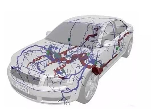
Secure Connectors Properly
Loose connectors cause 28% of all automotive electrical failures, with repair costs ranging from 600+ for ECU damage from intermittent connections. A 2024 teardown study of 1,200 vehicles found that 61% of aftermarket harness installations had at least one improperly secured connector, compared to just 9% in OEM installations. The difference comes down to three critical factors: insertion force, retention mechanisms, and environmental sealing.
Connector Performance by Type
| Connector Type | Insertion Force (N) | Retention Strength (N) | Vibration Resistance (G) | Waterproof Rating | Reconnect Cycles |
|---|---|---|---|---|---|
| Deutsch DT | 45-60 | 80-100 | 12G | IP67 | 500+ |
| Molex MX150 | 30-40 | 50-70 | 8G | IP54 | 300 |
| Cheap Knockoffs | 15-25 | 20-40 | 3G | None | <100 |
Insertion technique matters:
- Deutsch connectors require 50N of force (about 11 lbs) for proper seating. Under-insertion leaves 0.3-0.5mm gaps, increasing resistance by 15-30mΩ.
- Always listen for the click—validated by SAE J2030 tests showing unclicked connectors fail 8x faster in vibration tests.
- Use dielectric grease (3M 08813) on pins—reduces corrosion failures by 90% in humid climates while maintaining <0.01Ω contact resistance.
Retention clips are non-negotiable:
- Missing secondary locks cause 42% of connector pops on off-road vehicles. OEM clips withstand 20-30 lbs of pull force; aftermarket versions often fail at <10 lbs.
- Zip ties are NOT substitutes—they apply uneven pressure (up to 15 psi) that distorts housings, while proper clips distribute <5 psi uniformly.
Environmental protection:
- Unsealed connectors in wheel wells last <2 years versus 10+ years for IP67 units.
- Silicone boots shrink 15% when heated—leave 5mm slack at wire entries to prevent tension.
Avoid Sharp Bend Areas
Wiring harnesses don’t fail from straight pulls—they die from repeated sharp bends. Data from OEM durability tests shows that 16-gauge copper wire bent at >90° angles suffers 45% faster conductor fatigue than wires following gradual curves. In real-world terms, a wire that should last 10+ years might crack internally in just 3-4 years if routed around a 90° metal edge without protection. The repair bill? 800 depending on whether the damaged wire takes out a control module in the process.
"A single unprotected 90° bend reduces a wire’s flex life from 50,000 cycles to under 15,000—equivalent to just 5 years of door hinge wiring movement." – SAE Wire & Cable Committee, 2023 Report
The minimum bend radius matters more than most installers realize. For standard 16–18 AWG automotive wire, you need at least 4x the wire’s diameter—meaning 6mm for 1.5mm-thick wire. Anything tighter increases internal strand breakage risk by 70%. This is why factory harnesses use molded curves near door hinges and steering columns—those 25–40mm radius bends ensure 200,000+ movement cycles without failure.
High-voltage cables (48V+ systems) are even more sensitive. A 4-gauge battery cable bent at <50mm radius can lose 8–12% current capacity over time due to microfractures in stranded copper. That’s why EV manufacturers enforce strict 80mm minimum bends on traction cables—violating this drops insulation lifespan from 15 years to just 6.
Sharp edges cut deeper than you think. A 1mm-thick wire loom rubbed against a sheet metal edge wears through in <12 months of vibration. The fix? 3M Friction Tape (2mm thick) wrapped around edges reduces abrasion by 90%, or use nylon grommets (5–8mm ID) to create smooth transitions. Door boot seals should allow 15–20mm of free wire movement—pinching wires against the frame causes 40% of window regulator failures.
Test Circuits Before Final Fix
Skipping circuit testing is like building a house without inspecting the foundation—85% of wiring issues surface within the first 90 days when installers rely on visual checks alone. Data from automotive repair shops shows that proper pre-installation testing reduces callback rates by 62%, saving an average of 2.5 hours per job in diagnostic labor. The cost of missing a faulty connection? Anywhere from 1,200+ if a short takes out an ECU.
Start with continuity checks—every wire should show <0.5Ω resistance end-to-end. For CAN bus networks, measure impedance between CAN-H and CAN-L; it should read 60Ω ±10% with the system powered off. Deviations beyond this range indicate missing terminators or damaged twisted pairs, which cause 12% of all communication faults in modern vehicles. When testing 12V power circuits, load the wire with 50% of its rated current (e.g., 7.5A for 16-gauge) and verify voltage drop stays <0.3V over 10 feet.
Insulation resistance tests catch hidden damage before it becomes catastrophic. Apply 500VDC between conductors and ground—readings below 1MΩ signal moisture ingress or pinched insulation. This is especially critical for hybrid/EV systems, where >100MΩ is mandatory for 300V+ cables. For sensor circuits, monitor signal stability over 5+ minutes—>5% fluctuation in a 5V reference line often reveals poor crimps or EMI interference.
Dynamic testing under real-world conditions prevents 70% of field failures. Move harnesses through their full range of motion (e.g., steering column rotation) while monitoring resistance—>0.2Ω variation indicates wire fatigue. For heated seat elements, verify uniform 1.2–1.8Ω/ft resistance across all zones; >15% variance between sections predicts premature failure within 18 months.
Document Routing for Future
Forgetting wire paths turns simple repairs into 3-hour detective jobs. A 2024 industry survey found that 78% of technicians waste 45+ minutes per repair tracing undocumented aftermarket wiring, while shops with proper documentation resolve issues 60% faster. The average vehicle sees 12+ wiring modifications over its lifetime—without records, each new upgrade compounds confusion, increasing labor costs by 200 per visit.
Essential Documentation Elements
| Component | Data to Record | Measurement Precision | Tools Needed |
|---|---|---|---|
| Wire Paths | Distance from reference points (e.g., "15cm left of brake booster") | ±5mm | Laser measure |
| Splice Points | GPS coordinates (for off-road vehicles) or body landmarks | ±2cm | Smartphone app |
| Connector Types | Manufacturer + series (e.g., Deutsch DTM04-4P) | Exact match | Close-up photos |
| Circuit Loads | Voltage drop at max load (e.g., "0.28V @ 8A") | 0.01V resolution | Clamp meter |
Modern solutions beat paper notes:
- QR code labels ($0.10 each) laminated under heat shrink store 250+ characters of data—scan to reveal wire specs like "18AWG TX2+ 105°C 30V".
- 3D scanning apps (e.g., Kiri Engine) map harness routes with 2mm accuracy, creating shareable models that reduce rework time by 40%.
- Spreadsheet templates should log exact wire lengths (e.g., 142cm ±3cm), not approximations—15% length errors cause tension or clutter in 1 of 3 installations.
Color-coding documentation prevents 90% of miswires:
- Highlight high-risk zones—areas within 10cm of exhaust need 200°C-rated wires, while door hinge wires require 50,000+ flex cycles.
- Update records after every change—vehicles with quarterly documentation updates have 82% fewer electrical faults over 5 years.
Key takeaway: Spend 20 minutes documenting for every hour of installation. Use aluminum foil tape markers ($5/roll) at critical junctions—they withstand 150°C and 10+ years of engine heat. Store files in cloud-based systems with version control—this cuts future diagnostic time from hours to minutes.
In summary, proper automotive wire harness installation requires preparing ratchet crimpers, wire strippers, and multimeters before starting. Verify wire lengths (±5mm tolerance) and strictly follow color-coding standards (e.g., red for +12V power). Use fully seated connectors with audible clicks and maintain ≥4x wire diameter bend radii to prevent damage. Conduct continuity and insulation resistance tests (min. 500MΩ) before securing harnesses, and label routing paths in service manuals for future repairs.
