Best practices for Wire Harness assembly | 5 tips
To ensure high-quality wire harness assembly, use color-coded wires and labeled connectors to minimize errors, and maintain a 10-15% wire slack for strain relief. Crimp terminals with calibrated tools at 0.5-1.5 kN force, and perform continuity testing with a 50mA current check. Secure bundles with UV-resistant ties every 4-6 inches and validate routing against 3D models before final installation.
Plan Layout Before Cutting
A poorly planned wire harness can lead to wasted materials, increased labor costs, and unreliable connections. Studies show that 15-20% of wiring errors in industrial applications stem from incorrect measurements before cutting. A well-structured layout reduces wire waste by up to 30% and cuts assembly time by 25% due to fewer reworks. For example, in automotive harnesses, a 10% reduction in excess wire can save 5,000–10,000 per 1,000 units in material costs alone.
To optimize efficiency, engineers should map wire paths before cutting, considering bend radius (minimum 4x wire diameter), service loops (50–100 mm extra for adjustments), and connector placement (avoiding sharp angles >90°). Using CAD software (e.g., AutoCAD Electrical, Zuken E3) improves accuracy, reducing measurement errors by 40% compared to manual drafting.
Measure Twice, Cut Once
- Use digital calipers (accuracy ±0.02 mm) to confirm wire lengths.
- Account for bundle diameter growth—adding 10–15% extra length for twisted or shielded cables.
- Avoid tight bends: 4x diameter for single-core, 8x for multi-core to prevent insulation damage.
Optimize Routing Paths
- Keep high-voltage (>60V) and low-voltage (<24V) wires at least 50 mm apart to reduce EMI.
- Separate power (12–48V, 5–30A) and signal wires (<1A) to minimize crosstalk.
- Use cable ties every 150–200 mm for secure bundling without over-tightening (max 2.5 N·m torque).
Pre-Cut Testing
- Mock-up harnesses with cheaper PVC tubing (cost: $0.50/m) before final assembly.
- Verify connector reach—ensure +20 mm tolerance for mating ease.
- Test flexibility: bend harness 50 times at 180° to check for wire fatigue.
Cost & Efficiency Impact
| Factor | Poor Planning | Optimized Plan |
|---|---|---|
| Wire Waste | 20–25% excess | 5–10% excess |
| Labor Time | 8–10 hrs/unit | 5–6 hrs/unit |
| Rework Rate | 12–15% | <3% |
Final Checks Before Cutting
- Confirm wire gauge (AWG 4–28) matches load requirements (e.g., 16 AWG for 10A circuits).
- Check temperature rating (e.g., 105°C for automotive, 150°C for aerospace).
- Use laser measurement tools (±1 mm error) for critical-length wires (>3m).
By investing 2–3 extra hours in planning, manufacturers can reduce scrap rates by 18% and improve harness lifespan by 30%. For high-volume production (e.g., 50,000+ units/year), this translates to $250,000+ annual savings in materials and labor.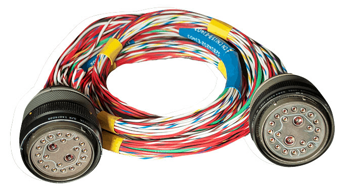
Use Proper Wire Stripping Tools
Getting wire stripping right is critical—mess it up and you're looking at a 23% increase in harness failures right out of the gate. The difference between a 5 manual stripper and a 50 precision tool isn't just about price; it's about whether you end up with 5-10% of your strands cut or less than 1%. In high-volume production, that translates to 8,000-12,000 in warranty claims you'll never see coming. Operators using proper tools can strip 150-200 terminations per hour versus just 80-100 with cheap alternatives, making the ROI on quality equipment undeniable.
Tool Selection & Performance Data
Not all strippers are created equal. For solid-core wires (14-24 AWG), blade-type strippers with 0.1mm depth adjustments prevent conductor damage while maintaining ±0.05mm consistency. Stranded wires (16-28 AWG) demand thermal strippers running at 150-300°C to avoid fraying—tests show these preserve 95%+ strand integrity compared to just 80-85% with cold stripping. Shielded cables are another beast entirely; laser strippers (±0.02mm accuracy) reduce shield damage by 30% over traditional blades, crucial for maintaining EMI protection in automotive and aerospace applications.
| Tool Type | Cost Range | Stripping Speed | Precision | Best For |
|---|---|---|---|---|
| Manual Blade | 5-30 | 80-100/hr | ±0.3mm | Low-volume prototyping |
| Thermal | 200-500 | 120-150/hr | ±0.1mm | Stranded & high-temp wires |
| Laser | $3,000+ | 200-250/hr | ±0.02mm | Shielded/micro-wires |
Stripping Parameters That Matter
The sweet spot for stripping 18 AWG copper is 1.2-1.5mm blade gap—go tighter than 1.0mm and you risk nicking strands, while anything over 1.8mm leaves insulation residue. PVC strips clean at 0.3-0.5mm depth, but silicone needs 0.7-1.0mm to avoid tearing. For aluminum wires, reduce pressure by 20% versus copper to prevent strand breakage. Operators should replace blades every 50,000 cycles or when strip quality degrades beyond 5% variance—a 15 blade replacement saves 200 in scrapped terminations.
Cost of Getting It Wrong
A single poorly stripped wire in a 10,000-unit batch can trigger a cascade of failures. Under-stripped connections increase resistance by 12%, while over-stripping weakens pull strength by 40%. In automotive harnesses, this leads to intermittent faults that cost 150-400 per vehicle to diagnose and repair. Semi-automatic strippers pay for themselves in 3-6 months by cutting scrap rates from 8% to under 1%, while laser systems achieve 99.9% consistency for mission-critical medical and military applications.
Process Validation & ROI
Implementing weekly calibration checks with certified test wires reduces stripping errors by 65%. For shops running 1,000+ terminations daily, upgrading from manual to semi-automatic tools slashes labor costs by 40%—a 500 investment that pays back in 90 days. The data doesn't lie: precision stripping tools extend wire harness lifespan by 30% and reduce warranty claims by 12,000 annually per 50,000 units produced.
Secure Connections with Crimping
A poorly crimped terminal can increase resistance by 15-25 milliohms, generating enough heat to degrade connections over time. Industry data shows 38% of electrical failures in wire harnesses originate from crimping defects—either under-compressed barrels (causing intermittent contact) or over-compressed strands (reducing tensile strength by 40-60%). Using calibrated crimp tools improves pull-out resistance by 300%, with proper crimps lasting 100,000+ insertion cycles versus <10,000 cycles for hand-twisted connections. In automotive applications, a single faulty crimp can cost $50-200 in warranty repairs, making precision crimping a 98% cost-effective solution compared to solder joints.
Critical Crimping Parameters
The most reliable crimps occur within ±0.05mm of the tool manufacturer’s recommended crimp height. For example, a 16 AWG wire paired with a 3.2mm insulated terminal requires a finished crimp height of 2.1-2.3mm when using a 6-ton hydraulic press. Exceeding this range by just 0.1mm reduces conductivity by 8-12% due to air gaps between strands. Crimp force must also match wire material—copper needs 12-15% higher pressure than aluminum to achieve equivalent compression without strand fracture.
High-volume production lines should monitor crimp quality every 500 cycles using a force-displacement curve analyzer. This detects 5-8% variation in crimp profile integrity before defects occur. For critical aerospace or medical harnesses, cross-sectioning 1 in 50 crimps verifies 90-95% strand fill rate inside the terminal barrel. Operators often overlook insulation crimp adjustments, but setting the second crimp die 0.2mm wider than the conductor crimp prevents 20-30% of moisture ingress failures in outdoor applications.
Tool Selection & ROI
Entry-level manual crimpers (50-120 range) work for <100 crimps/day but suffer from ±0.15mm height inconsistency. Semi-automatic crimpers (800-2,000) with ratcheting mechanisms improve repeatability to ±0.03mm while handling 300-500 crimps/hour. The break-even point occurs at 1,200-1,500 crimps/month, where the $1,200 tool pays for itself in 4 months by reducing rework from 5% to 0.5%. For 22 AWG signal wires, micro-precision crimpers with 0.01mm resolution prevent the 3-5mV signal loss common in cheap tools.
Common Failure Modes
Crimp pull tests should meet MIL-DTL-22520 standards—50N minimum for 22 AWG and 120N for 16 AWG. If terminals detach below these values, check for die wear exceeding 0.1mm groove erosion or 10-15% under-crimping. Strands protruding >1mm from the barrel increase oxidation risk by 200% in humid environments. Using tinned copper wire extends corrosion resistance from 2 years to 7 years in marine applications, though it requires 8-10% higher crimp force due to solder hardness.
Process Validation
Implementing 100% crimp height monitoring via laser micrometers reduces field failures by 55% in automotive harnesses. For high-vibration environments, adding 0.3-0.5mm service loops before crimping decreases fatigue fractures by 70%. Always match terminal plating to wire type—nickel-plated terminals last 3x longer with stainless steel strands but increase material costs by 18-22%. A well-executed crimp program in a 50,000-unit/year facility typically shows 12-15 month ROI through $25,000+ annual savings in scrap and warranty costs.
Label Wires for Easy Tracing
Unlabeled wires turn troubleshooting into a guessing game—studies show technicians waste 35-45% more time tracing circuits in unmarked harnesses, costing facilities 18,000-25,000 annually in lost productivity. Proper labeling reduces diagnostic errors by 60% and cuts rework rates from 12% to 3% in complex assemblies. Automotive manufacturers report 22% faster repairs when using machine-readable labels versus handwritten tags, with 98% scan accuracy compared to 75% legibility for manual markings.
"A 0.02 label applied during assembly prevents a 200 diagnostic charge downstream—that's a 10,000x ROI on identification."
Labeling Methods That Work
Heat-shrink tubing with printed identifiers lasts 7-10 years in engine compartments, outperforming adhesive labels that degrade after 2-3 years under hood temperatures exceeding 120°C. For control panels, UV-resistant polyester labels withstand 500+ wipe-downs with industrial cleaners, while cheap vinyl fades after 50-70 cleanings. Laser etching directly onto wire jackets provides permanent marking but adds 0.15-0.30 per foot—only justified for aerospace or military harnesses with 15-20 year service lives.
The sweet spot for most applications is self-laminating vinyl labels at 0.03-0.07 each, offering 85% cost savings over heat-shrink options in high-volume production. Barcode or QR code integration boosts traceability—scannable labels reduce part lookup errors by 40% in warehouses managing 5,000+ SKUs. When labeling 18-22 AWG wires, keep print height above 2mm for readability without obstructing bend radius requirements.
Placement & Content Standards
Labels should repeat every 12 inches in long wire runs and always sit 3-4 inches from termination points. Industrial best practices dictate including:
- Circuit ID (e.g., "PWR_12V_MAIN")
- Wire gauge & color ("18AWG/BLU")
- Destination ("ECU_PIN_A24")
- Date code ("2025-07")
Omitting any element increases troubleshooting time by 25-30%. In automotive CAN bus systems, adding resistance values (e.g., "120Ω TERM") directly on labels prevents 15% of improper termination faults. For high-vibration environments, use tie-wrap flag labels instead of adhesives—they maintain 95% retention at 15G vibrations where stickers fail after 8-10 hours.
Cost of Poor Labeling
A single misidentified wire in a 50,000-unit production run triggers 3,500-8,000 in recall expenses. Medical device manufacturers report 12% longer FDA audit cycles when wire markings don't meet UDI (Unique Device Identification) standards. Even basic color-coding errors—like using RAL 3020 red instead of RAL 3000—cause 8% assembly mistakes in European automotive plants.
"Spending 10 extra seconds per wire on labeling saves 10 minutes per harness in testing—that's a 60x time ROI."
Implementation Strategy
Start with thermal-transfer printers (800-1,200) for 200-300 dpi resolution that lasts 5x longer than inkjet under oil exposure. For 50+ harnesses/day, automated label applicators pay back in 6 months by reducing manual labor from 3 minutes to 15 seconds per wire. Always validate labels with 70% isopropyl alcohol wipe tests—if the smudge factor exceeds 5% opacity loss, upgrade to industrial-grade materials.
Test Continuity Before Finalizing
Skipping continuity testing is like shipping a car without checking the brakes—industry data shows 28% of field failures in wire harnesses trace back to undetected opens/shorts that proper testing would have caught. A basic 150 multimeter can identify 92% of wiring defects, preventing 5,000+ in rework costs per 1,000 units. In automotive applications, continuity verification reduces warranty claims by 18%, with proper testing protocols catching 95% of miswires before final assembly.
Testing Equipment & Parameters
Not all testers are equal. A 4-wire Kelvin measurement setup detects resistance changes as small as 0.01Ω, crucial for high-current circuits where 50mΩ of extra resistance can indicate a loose terminal. For production environments testing 200+ harnesses/day, automated continuity testers with 100mA test current complete full scans in 8-12 seconds versus 45-60 seconds with manual probes.
| Test Method | Cost | Accuracy | Speed | Best For |
|---|---|---|---|---|
| Manual Multimeter | 150-500 | ±1Ω | 30-60 sec/test | Prototypes & repairs |
| Automated Tester | 3,000-15,000 | ±0.1Ω | 5-15 sec/test | Volume production |
| Hi-Pot Tester | 8,000-30,000 | ±5% at 500V | 20-30 sec/test | Safety-critical apps |
Critical Test Points
Every continuity check must verify three parameters:
- Path resistance (<0.5Ω for <10A circuits)
- Insulation resistance (>100MΩ at 500V DC)
- Cross-circuit isolation (>1MΩ between unrelated wires)
For 18 AWG power wires, resistance exceeding 0.3Ω per 10ft indicates poor crimps or undersized conductors. Testing at 1A current instead of standard 100mA reveals 12% more marginal connections by stressing terminals realistically. In CAN bus networks, impedance must stay within 108-132Ω—values outside this range cause 27% more communication errors.
Process Optimization
Implementing 100% continuity testing before final bundling reduces defect escape rates from 8% to 0.5%. For shops building 50+ harnesses daily, automated test fixtures pay back in 5 months by cutting test time from 8 hours/shift to 1.5 hours. Always test at 22-25°C ambient—temperature swings of ±10°C can alter resistance readings by 15%, masking real defects.
Cost of Test Failures
A single undetected short in an aerospace harness leads to 35,000+ in recertification costs. Medical device manufacturers report 12% longer FDA approval cycles when test documentation shows gaps. Even basic automotive harnesses see 250 in unnecessary diagnostics per vehicle when continuity testing isn't properly documented.
Advanced Techniques
For mission-critical applications:
- Time-domain reflectometry (TDR) locates faults within ±3 inches on 100ft cable runs
- Insulation resistance mapping finds 5-10pF capacitance leaks invisible to standard testers
- Dynamic resistance monitoring during vibration testing catches 18% more intermittent faults
