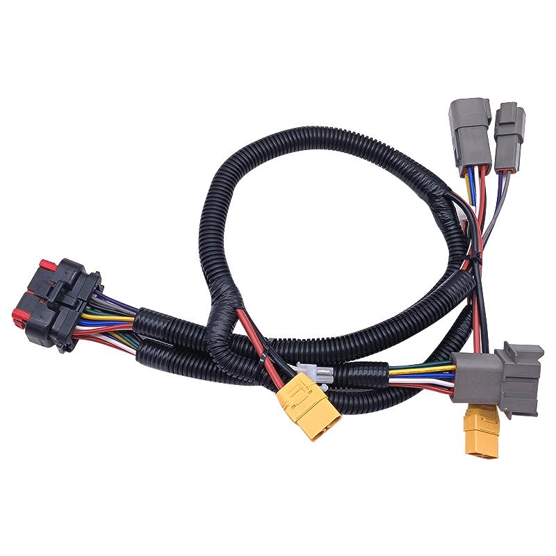
Custom Molex Wire Harness Design | Specifications & Manufacturing process
Customizing a Molex harness requires providing terminal part numbers, cable specifications (e.g., 22AWG), and connector pinouts.
The manufacturing process involves crimping with specialized tooling and performing mating force tests to ensure over 5000 mating cycles and reliable electrical performance.
Specifications
A typical specification sheet must be precise, covering: wire range from 26AWG (0.13mm² / 0.5A) to 14AWG (2.08mm² / 15A), operating temperature range such as -40℃ to 105℃, and clearly specifying connector series (e.g., Mini-Fit Jr. 5566 series) and required safety certifications (e.g., UL/CSA).
Electrical Performance
Current Carrying Capacity and Wire Selection
Current carrying capacity is the fundamental basis for selecting wire gauge. It primarily depends on the conductor's cross-sectional area (expressed in AWG) and the operating environment's temperature.
-
Current and Temperature Rise: When current flows through a wire, heat is generated due to conductor resistance, causing the wire temperature to rise. Standard ampacity tables (as defined in UL 1015, IEC 60287) typically provide rated current values at a specific ambient temperature (e.g., 30°C). For example, a 22AWG wire might be rated for 7A at 30°C ambient. But if the ambient temperature rises to 80°C, its safe current-carrying capacity must be derated, possibly to 4A or lower, to prevent insulation aging or melting from overheating.
-
Derating for Wire Bundles: When multiple wires are tightly bundled together, their heat dissipation capability decreases. Typically, for a bundle containing more than 3 wires, the ampacity of each wire needs to be derated by 20% or more compared to a single wire.
Voltage Rating and Insulation Effectiveness
-
Working Voltage vs. Test Voltage: The voltage a harness must withstand includes not only the normal operating voltage but also transient surge voltages that may occur in the system. For example, a harness for a 24V DC system might require its insulation system to withstand a Hi-Pot test of at least 1500VAC for 60 seconds without breakdown.
-
Insulation Resistance: This measures the insulation material's ability to prevent current leakage. Typically measured after applying 500VDC, requiring insulation resistance greater than 1000 Megohms per kilometer of cable.
Signal Integrity Considerations
-
Characteristic Impedance and Matching: High-speed signal lines (e.g., USB, HDMI, differential pairs) require constant characteristic impedance (e.g., 90Ω±10%).
-
Shielding Effectiveness: To prevent external Electromagnetic Interference (EMI) from affecting signals, or internal signals from radiating and interfering with other equipment, shielded cables are used. Shielding effectiveness is determined by the shield type and coverage:
-
Foil Shield: Provides 100% coverage, often used for high-frequency interference suppression.
-
Braided Shield: Coverage typically between 70% and 95%, provides better low-frequency interference protection and mechanical strength.
-
Shielding effectiveness is usually expressed in decibels (dB); for example, achieving 60dB attenuation at 100MHz reduces interference to one-millionth.
-
-
Crosstalk: When multiple wires (especially mixed power and signal) run parallel over long distances, a signal on one wire can be induced onto an adjacent wire.
Voltage Drop Calculation
For harnesses transmitting power over long distances, voltage drop is a parameter that must be calculated. Excessive voltage drop can cause insufficient voltage at the load end, affecting equipment performance.
The voltage drop (ΔV) calculation formula is: ΔV = I × R × L × 2
Where I is the current (A), R is the resistance per unit length of the wire (Ω/m, available from standard tables, e.g., ~52.0 mΩ/m for 22AWG copper wire), L is the cable length (m), multiplied by 2 accounts for the round trip (two conductors).
For example, a 12V system, using 22AWG wire to power a device 2 meters away with a continuous current of 2A:
ΔV = 2A × 0.052Ω/m × 2m × 2 = 0.416V
The voltage drop rate is 0.416V / 12V ≈ 3.5%, which is generally acceptable. However, if the current or length increases, the voltage drop might exceed the allowable limit (typically <5%), necessitating the selection of a thicker wire (e.g., 20AWG or 18AWG) to reduce resistance.
Physical Specifications
Connector Mating is the Physical Foundation
-
Series and Model: For example, Molex Mini-Fit Jr. 5566 series, or Micro-Fit 3.0 43025 series. Different series have different latch mechanisms, current ratings, and pin pitches.
-
Pin Positions and Cavities: A detailed pinout diagram must be provided, indicating the signal or power corresponding to each terminal cavity.
-
Connector Keying and Color: Many Molex connectors offer physical polarization keying options and different colored housings to prevent mis-mating when interfaces are similar.
Wire Length and Tolerances Control Installation Accuracy
-
Nominal Length and Tolerances: For example, a main trunk length specified as 450mm ±5mm. The tolerance band should be set according to the total harness length; short wires (<100mm) might have a tolerance of ±2mm, while long wires (>1m) might have ±10mm.
-
Branch Point Locations: Dimensional drawings must indicate the distance of branch points from connectors, e.g., branch point B is located 150mm from connector A on the main trunk.
-
Harness Shrinkage Factor: When wires are bundled, their effective length is shorter than individual wires. This shrinkage factor, typically 1-3% of the bundle diameter, must be considered during design.
Harness Diameter and Bend Radius Determine Routing Path
-
Bundle Diameter Calculation: Estimated formula for harness outer diameter: 1.2 × √(sum of squares of all wire diameters). For example, a bundle containing 20 wires with 0.8mm outer diameter ≈ 1.2 × √(20 × 0.8²) ≈ 4.3mm.
-
Minimum Bend Radius: During installation, the harness must not be bent beyond its minimum bend radius to avoid damaging internal wires. Typically, the minimum bend radius for static installation is 5 times the harness diameter; for dynamic, repeated bending applications, it may require 10-15 times.
Wire Color and Marking for Quick Identification
-
Basic Color Code: Use standard colors to indicate circuit function, e.g., Black for ground, Red for positive power, White/Blue for signal lines.
-
Zebra Stripe Marking: When colors are insufficient, use base color with contrasting stripe wires, e.g., Green with Yellow stripe.
-
Inkjet Marking: Directly print numbers or function codes on the wire insulation, e.g., "SENSOR_5V", "MOTOR_A+". Marking spacing is typically 100mm to 200mm.
Protective Materials for External Stress
-
Split Sleeving: Suitable for areas requiring frequent inspection or adding branches, provides basic abrasion protection.
-
Closed-End Convoluted Tubing: Provides a higher level of mechanical protection, suitable for areas subject to crushing, abrasion, e.g., inside robotic arms.
-
Braided Sleeving: Good heat dissipation and flexibility, aesthetically pleasing, often used for visible harnesses in race cars or industrial equipment.
-
Insulation Tape: Used for bundling and insulating at harness branch points or ends.
Clamp Types and Locations Ensure Stability
-
Clamp Selection:
-
Nylon Cable Ties: Economical and universal, but may indent the harness.
-
Adhesive-Backed Clamps with Pads: Suitable for mounting on smooth surfaces.
-
Threaded Hole Mount Clamps: Provide the most secure mechanical fixation.
-
-
Clamp Spacing: The maximum distance between fixed points is typically 300mm. Stress concentration points like connector roots or branch points must have a clamp within 50mm.
-
Strain Relief: A strain relief structure must be designed at the rear of the connector, e.g., using a clamp to crimp the harness jacket to the connector, or applying a section of heat shrink tubing, to prevent pull force from acting directly on the terminal crimp points.
Environmental Durability
Definition of Temperature Range
-
Operating Temperature: Refers to the ambient temperature range the harness can withstand while powered. For example, standard PVC insulation is typically suitable for -40°C to 105°C; whereas silicone or cross-linked polyethylene materials can be used for -65°C to 150°C or even higher temperatures. Wire ampacity decreases as ambient temperature rises; design must refer to derating curves in standards like UL 1581.
-
Storage Temperature: Refers to the extreme temperature the product can withstand in a non-operating state, usually a wider range than operating temperature, e.g., -55°C to 85°C.
-
Thermal Cycling: Simulates day/night or seasonal temperature variations, and temperature changes due to equipment power cycling. Test conditions might require 500 cycles between -40°C and 125°C, each cycle including 30 minutes at extreme temperatures and 5 minutes transition time.
Dust and Water Ingress Protection (IP) Rating
-
First Digit (Solid Particle Protection): Levels from 0 to 6. For example, IP5X indicates dust-protected; while not completely dust-tight, ingress does not interfere with operation; IP6X indicates complete dust-tightness.
-
Second Digit (Liquid Ingress Protection): Levels from 0 to 9K. Common levels include:
-
IPX4: Protected against water splashing from any direction.
-
IPX7: Protected against temporary immersion (e.g., 1 meter depth for 30 minutes).
-
IPX9K: Protected against high-pressure, high-temperature jet spraying (e.g., 80°C water from close range).
-
-
For the complete interface formed after connector mating, its IP rating needs to be explicitly verified. For example, some of Molex's sealed connector series (e.g., MX150 series) are designed to meet IP67 or IP69K requirements.
Chemical Resistance
-
Common Fluids: Must explicitly list potential chemical exposures, such as engine oil, transmission fluid, brake fluid, gasoline, diesel, coolant, cleaning agents (e.g., isopropyl alcohol), acids, bases, etc.
-
Material Selection: Different jacket and insulation materials have different resistances. For example, TPU has good resistance to mineral oils and cutting fluids, while CPE has better stability against ozone and UV. Test standards (e.g., ISO 1817) evaluate material volume change rate (typically required < ±25%), hardness change, and tensile strength retention after immersion in specific fluids (e.g., IRM 903 oil) for a set time (e.g., 70 hours / 100°C).
Resistance to Vibration and Mechanical Shock
-
Vibration Testing: According to standards like ISO 16750-3, test conditions may include frequency range (e.g., 10Hz to 2000Hz), acceleration (e.g., 5g to 30g), and duration (e.g., 8 hours per axis).
-
Mechanical Shock: Simulates severe impacts during transportation or use. Test conditions might be a half-sine shock pulse, 50g acceleration, 11ms pulse duration, 3 shocks in both directions of three orthogonal axes.
-
Countermeasures: Include using secondary locks to prevent terminal withdrawal, providing sufficient clamp points along the harness route (spacing typically ≤ 300mm), and applying strain relief at connector roots.
Flammability Rating Requirements
-
UL 94 Standard: This is the most common flammability standard for plastic materials. Common ratings:
-
V-0: After two 10-second flame applications, flame extinguishes within 10 seconds, no burning drips.
-
V-1: After two 10-second flame applications, flame extinguishes within 30 seconds.
-
V-2: Similar to V-1, but allows burning particles to drip.
-
HB: Burns at a rate below a specified value in horizontal burn test.
-
-
Material selection must meet specific safety standards for the target market or industry, e.g., consumer electronics may require V-1, while automotive interior parts may require V-0.
Resistance to UV and Ozone
-
UV Aging: Long-term exposure to sunlight can make some materials (e.g., standard PVC) brittle and crack. Solutions include using materials with UV stabilizers (e.g., carbon black added to PVC) or selecting inherently UV-resistant materials (e.g., cross-linked polyethylene).
-
Ozone Attack: Ozone attacks the molecular chains of certain elastomers. For example, ordinary rubber cracks quickly in an ozone environment. Materials like EPDM, resistant to ozone, must be used. Testing is often per SAE J2020, exposing samples to 50 pphm ozone at 40°C for 70 hours, then checking for surface cracks.
Manufacturing process
Taking a standard automated cutting machine as an example, it can process up to 60 kilometers of cable per day, with cutting accuracy controlled within ±0.1 millimeters, while simultaneously stripping the insulation, ensuring consistency for the starting point of every wire.
Wire Preparation
1. Incoming Material and Loading
Wire cables are typically delivered on reels, with reel weights ranging from 100 kg to 500 kg. During loading, the cable reel is mounted on a pay-off stand equipped with a tension control system. This ensures the cable maintains a constant, moderate tension (e.g., 1.5 to 2.5 Newtons for 22AWG wire) during unwinding, preventing over-stretching or twisting of the wire.
Before entering the processing area, the cable passes through a set of cleaning brushes or an ionizing air bar to remove surface dust and static electricity that may have accumulated during transport and storage.
2. Fully Automated Precision Cutting
The cutting operation is performed by a computer numerically controlled (CNC) fully automatic cutting machine. The operator downloads or directly inputs information such as wire specifications, cut length, and strip parameters from the Manufacturing Execution System (MES) into the machine.
-
Length Accuracy: High-end cutting machines use servo motors driving feed rollers coupled with high-resolution encoders. Typical cutting length accuracy can reach ±0.5 mm or ±0.1% (whichever is greater). For example, for a required 1000 mm wire, the actual produced length will be between 999.5 mm and 1000.5 mm.
-
Blade Configuration: The machine is equipped with two sets of blades.
-
Main Cutters: Used to cut the cable to the predetermined length. Blade life is typically measured in cut cycles; when cutting copper conductors, life can reach 500,000 to 1,000,000 cycles before sharpening is needed.
-
Strip Blades: Used to remove the insulation jacket. The opening/closing depth of the blades can be finely adjusted based on the cable's outer diameter, with precision up to ±0.02 mm, ensuring only the insulation is cut without damaging any copper strands.
-
Typical Strip Blade Depth Settings for Common Wire Gauges (Example)
| Wire Gauge (AWG) | Average Outer Diameter (mm) | Recommended Strip Blade Depth (mm) |
|---|---|---|
| 24 | 1.0 | 0.4 - 0.5 |
| 22 | 1.4 | 0.6 - 0.7 |
| 20 | 1.8 | 0.8 - 0.9 |
| 18 | 2.2 | 1.0 - 1.1 |
3. Insulation Stripping and Handling
The stripping process involves three steps: cutting, gripping, and pulling. The machine first makes a circumferential cut in the insulation using the strip blades. Then, a pair of grippers tightly clamp the severed insulation section and pull it straight off the wire.
For complex cables, stripping requirements are more involved:
-
Multi-Level Stripping: Some cables require two stripping operations at the same end. For example, first stripping 5mm of the outer jacket, then stripping 3mm of the inner insulation (for twisted pairs).
-
Shield Processing: For coaxial or shielded cables, the stripping machine can be configured with three or more blade sets to sequentially strip the outer jacket, shield braid, and inner insulation, while controlling the fold-back length of the shield, e.g., requiring a fold length of 2.0mm ±0.5mm.
4. Strand Twisting and Conductor Inspection
After stripping, the exposed multi-strand copper wires may become loose due to the stripping action. Therefore, the next step is twisting.
A high-speed rotating twister head will twist the copper strands a preset number of turns (e.g., 3 turns clockwise) to make them tighter and more rounded, facilitating smooth insertion into the terminal and subsequent crimping.
Following this, a vision inspection system (e.g., a 5-megapixel CCD camera) integrated at the machine's outlet immediately captures and analyzes the end of each wire. The system checks within milliseconds:
-
Strand Damage: Detects if any copper strands are cut due to excessive blade depth.
-
Insulation Residue: Confirms the insulation is completely removed, with no residue.
-
Copper Oxidation or Contamination: Checks the conductor surface color is normal.
Any non-conforming wires are automatically ejected into a scrap bin and recorded. The First Pass Yield (FPY) for this process is typically required to be above 99.8%.
5. Process Verification and Data Recording
Besides in-line inspection, quality engineers will randomly sample from the output at predetermined frequencies (e.g., every 2 hours) for more precise laboratory measurements:
-
Use an optical comparator to measure the stripped conductor length, verifying it meets the drawing tolerance (e.g., 3.0mm ±0.3mm).
-
Use a tension gauge to test the adhesion between the copper strands and the insulation, ensuring the stripping process hasn't weakened the cable's mechanical strength.
Pre-Assembly
Formboard Preparation and Accuracy Control
The formboard is the foundation of pre-assembly, typically made from lightweight, dimensionally stable materials like Medium-Density Fibreboard (MDF) or aluminum alloy plate. The board thickness is about 19 mm, with surface flatness error less than 0.5 mm/m.
-
Locating Pin Installation: The positions of locating pins on the formboard are machined by a CNC machine directly driven by the 3D digital model of the harness product. The positional tolerance of the pin holes is typically controlled within ±0.1 mm.
-
Modular Design: For production lines requiring frequent changeovers, formboards use a modular design. Standardized modules allow for quick replacement of different functional locating blocks, reducing changeover time from several hours to under 30 minutes.
-
Information Visualization: The board surface uses high-durability labels or laser engraving to clearly mark the part number, wire number, and routing arrows for each position.
Wire Layout and Branch Handling
For complex harnesses with over 50 branch points, the assembly sequence is optimized using process simulation software to ensure an optimal operator path and reduce repetitive motions.
-
Branch Point Protection: At wire branch intersections, rubber boots or convoluted tubing are pre-installed. The boot's flare direction must align with the wire's stress direction to provide optimal strain relief.
-
Dimensional Control: Use specialized gauges to check key dimensions, such as main trunk length (tolerance ±3 mm) and branch length (tolerance ±2 mm). For areas with special requirements, like sections needing to route around mechanical components, use a protractor to confirm the bend radius is greater than 5 times the cable diameter.
Bundling and Securing
The harness shape is fixed using bundling materials, selected based on the application:
-
Cable Tie Fixing: Common nylon cable ties (e.g., M3 specification) must have a tensile strength exceeding 50 Newtons. Install using a dedicated tool to ensure consistent tightness and automatically cut the excess tail.
-
Tape Wrapping: For areas requiring overall shaping, use PVC or cloth tape for wrapping. The standard overlap ratio is 50% of the tape width, ensuring full coverage without wrinkles.
-
Spiral Wrap Protection: For wire segments subject to frequent movement, use PP or PE spiral wrap for protection. The spiral wrap should have an elongation rate greater than 300% and fully retract after stretching.
In-Line Inspection and Data Recording
After completing an assembly unit, in-line inspection is performed:
-
Quick Continuity Test: Use a handheld tester to check the currently assembled section for shorts or opens via test points on the formboard. Test voltage is 5VDC, insulation resistance threshold is set to 1MΩ.
-
Vision Comparison System: A fixed industrial camera captures an image of the assembled section and compares it to a standard template, checking items like cable tie color, boot installation orientation.
-
Data Recording: The completion status and inspection results of each assembly step are recorded in real-time.
Connector Assembly
Preparation and Inspection Before Terminal Insertion
Before starting assembly, all components need to be verified:
-
Use a microscope or magnifier to check the terminal plating surface for uniformity, free of scratches or oxidation.
-
Measure key terminal dimensions, like contact point width and thickness, ensuring they meet the drawing tolerance of ±0.03mm.
-
Verify the connector housing's batch number and production date, confirming the material complies with RoHS and REACH standards.
Manual Insertion Operating Specifications
For low-volume production, manual insertion must follow standardized work procedures:
-
Operators wear grounding wrist straps and work on an anti-static workstation (surface resistance 10^6-10^9 Ω).
-
Use dedicated holding tools to handle terminals, avoiding direct contact with the plated areas.
-
Insert the terminal perpendicular to the housing; a click sound confirms proper seating.
-
After every 20 insertions, use a magnifier to inspect the recently inserted terminals.
Typical manual insertion speed is 15-25 terminals per minute, with an accuracy requirement above 99.5%.
Automated Insertion Equipment Configuration
High-volume production uses automated equipment, with key technical parameters including:
-
Servo motor driven, with repeatable positioning accuracy of ±0.02mm.
-
Equipped with a vision positioning system, camera resolution minimum 5 megapixels.
-
Includes real-time force monitoring, insertion force monitoring range 2-15N.
-
Automatically records the insertion time and force curve for each terminal.
Equipment operating data is uploaded in real-time via the MES system, creating a quality record for each terminal.
Locking Mechanism Verification Methods
The connector's locking mechanism must pass the following checks:
-
Primary Lock (audible/feel confirmation of terminal seating).
-
Secondary Lock (TPA mechanism) requires applying 25-35N force to verify its effectiveness.
-
The complete connector assembly must withstand a 50N axial pull test.
Test data is automatically recorded and linked to the product serial number.
Sealing Component Installation Specifications
For connectors requiring waterproofing:
-
Measure the compression of the seal before installation, ensuring it's within the 20%-30% range.
-
Use dedicated tools for installation to avoid twisting or stretching.
-
After installation, check the seal lip direction to ensure it matches the design.
Special Handling for High-Speed Differential Pairs
When handling high-speed signal connectors (e.g., USB 3.0):
-
Differential pair length matching tolerance is controlled within ±0.13mm.
-
Shield termination must ensure 360-degree circumferential contact.
-
Impedance testing must be controlled within ±10% of the nominal value.
Quality Monitoring During Assembly
In-line inspection systems include:
-
Machine vision checks terminal seating status.
-
Continuity testing verifies correct circuit connections.
-
Periodic sampling for X-ray inspection of internal structures.
Functional Testing
Test Preparation and Equipment Configuration
Before testing begins, the following preparations are required:
-
Test fixture interfaces must precisely match the harness connectors, with probe diameter tolerance controlled within ±0.01mm.
-
Test systems are calibrated regularly, voltmeter accuracy ±0.1%, resistance measurement accuracy ±0.5%.
-
Ambient temperature controlled at 23±5°C, relative humidity maintained between 30%-60%.
The test system typically includes:
-
Programmable Power Supply (output 0-100VDC/0-20A).
-
Multi-channel Data Acquisition Card (minimum resolution 16-bit).
-
High-Speed Switching Matrix (switching time <1ms).
-
Insulation Resistance Tester (test voltage 50-1000VDC).
Basic Electrical Performance Test Sequence
-
Continuity Test
-
Apply 1A test current, voltage drop threshold set to 50mV.
-
Measure loop resistance, standard requirement ≤50mΩ (including contact resistance).
-
Test speed: 500-1000 points/minute.
-
-
Insulation Resistance Test
-
Test conditions: 500VDC voltage, sustained for 60 seconds.
-
Pass criteria: ≥100 MΩ (general applications), ≥1000 MΩ (medical/aerospace).
-
Data recording: Measured resistance value and time curve for each wire.
-
-
Dielectric Withstand Voltage (Hi-Pot) Test
-
Test voltage: 1500VAC (for working voltage ≤300V).
-
Duration: 60 seconds.
-
Leakage current threshold: ≤5mA (medical equipment may require ≤2mA).
-
High-Speed Signal Integrity Testing
For differential pairs with data rates ≥1Gbps, perform:
-
Impedance Test: Use TDR instrument, require impedance deviation ≤ ±10%.
-
Insertion Loss Test: Attenuation ≤ -3dB at the Nyquist frequency.
-
Return Loss: ≥ -15dB @ 1GHz.
-
Delay Skew: Between differential pairs ≤ ±5ps.
Mechanical Performance Verification
-
Terminal Retention Force Test
-
Use a digital force gauge, pulling at 25mm/min speed.
-
Minimum retention force requirement: Signal terminals ≥50N, Power terminals ≥150N.
-
After test, inspect terminal plastic body for cracks or deformation.
-
-
Connector Mating/Unmating Force Test
-
Speed: 50mm/min.
-
Maximum insertion force ≤60N, minimum retention force ≥15N.
-
Mating cycle life test: Contact resistance change ≤10% after 500 cycles.
-
Environmental Suitability Testing
Perform the following environmental tests on samples:
-
Temperature Cycling: -40°C ~ +85°C, 1000 cycles, functional performance normal after test.
-
Vibration Test: 5-500Hz, 1 hour per axis in three orthogonal directions.
-
Salt Spray Test: Contact resistance change ≤20% after 96 hours.
Test Data Management
All test data is automatically recorded and linked to the product serial number:
-
Raw data retention period ≥ 10 years.
-
Test results uploaded to the MES system in real-time.
-
Non-conforming products are automatically locked and generate a defect report.
-
Test systems perform daily self-calibration; if error exceeds tolerance, the system is immediately taken offline.
After testing, qualified products are accompanied by a complete test report, including:
-
Measured data for each test item.
-
Test equipment ID and calibration status.
-
Test time and operator information.
-
Ambient temperature and humidity record.
