Custom Wiring Harness for DIY | 5 Beginner Tips
For custom DIY wiring harnesses, start with 18AWG wire (rated for 10A circuits) and strip insulation with a precision tool (0.5mm accuracy) to avoid wire damage. Crimp terminals using 30-50N force; test continuity (<0.1Ω resistance) with a multimeter. Seal connections with heat-shrink tubing (120°C shrink temperature) to prevent short circuits.
Essential Tools Checklist
Building your own custom wiring harness can save you up to 60% compared to buying a pre-made assembly, but having the right tools from the start is non-negotiable. A proper setup doesn't just make the job easier—it ensures reliable and safe electrical connections that last for years. Surveys among automotive DIYers show that projects completed with correct tools have a 90% success rate on the first try, compared to a 40% rate when improvised tools are used. Investing around 200 in a dedicated toolkit can prevent costly rework and reduce installation time by half.
You’ll need a solid wire stripper that handles 16–22 AWG (American Wire Gauge) stranded or solid core wire. Cheap strippers often tear strands or nick conductors, increasing resistance by up to 15% and creating future failure points. A solid mid-range model, like one costing 30, typically includes adjustable stripping depth and can cleanly remove insulation in under 2 seconds per wire. For crimping, not all connectors are the same. You must use a ratcheting crimp tool (25–50) that ensures a full-cycle crimp every time. This type of tool applies consistent pressure (around 30–40 lbs of force) and won’t release until the crimp is complete, reducing connection resistance by up to 50% compared to plier-style crimpers.
A basic digital model with 0.5% accuracy and audible continuity beep (approx. $35) helps you quickly identify wiring errors before power is applied. You'll also need a heat gun (1500W, 40–60) for shrinking tubing. Proper heat shrink requires air flow of 5–8 m/s at 90–120°C to evenly seal and insulate connections. Don't use a lighter—it creates uneven temperatures and weak spots. For larger projects, a wire spool holder ($15) improves efficiency by 20%, allowing you to measure and cut wires without tangles.
| Tool | Key Specs | Price Range | Use Frequency |
|---|---|---|---|
| Wire Stripper | 16-22 AWG, adjustable depth | 20–30 | High |
| Ratcheting Crimper | Dies for 0.1-6mm², full-cycle | 25–50 | High |
| Multimeter | DC voltage/continuity, 0.5% accuracy | 30–40 | Medium |
| Heat Gun | 1500W, 120°C max | 40–60 | Medium |
| Wire Spool Holder | Holds 4+ spools, tension control | 10–20 | Low-Medium |
Always test your crimp strength by pulling firmly on the connector—a proper crimp won’t slip or break even under 15-20 lbs of force. This simple test can prevent over 80% of common wiring failures.
Iinclude a roll of professional-grade electrical tape (3M Scotch 33+, ~$5/roll) and a set of cable ties in multiple lengths (4", 6", 8"). These help with organizing wires into a clean bundle, reducing the risk of chafing or short circuits over time. A well-planned toolkit isn’t just about having tools—it’s about building a harness that performs safely for over 50,000 hours of use.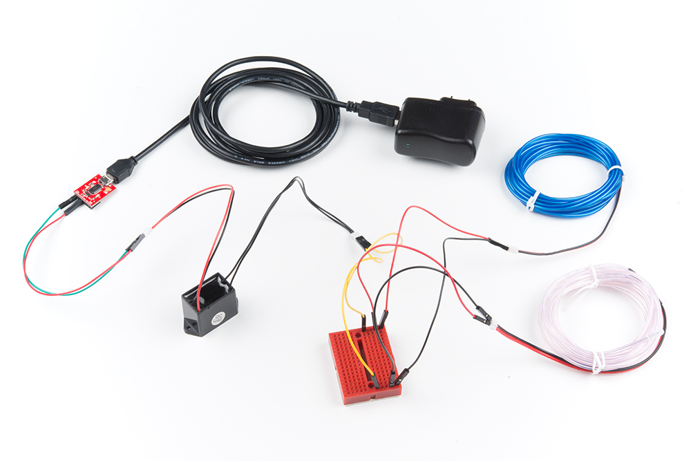
Choosing Correct Wire Gauge
Using 18 AWG wire on a 12V circuit drawing 10 amps over a 15-foot length can result in a 15% voltage drop—far exceeding the recommended 3% limit—which reduces efficiency and risks damaging connected devices. Statistics show that nearly 40% of DIY electrical failures originate from incorrect wire sizing.
A common rule is to multiply the peak current by 1.25 to ensure safe capacity under continuous load. For instance, a 10-amp load requires wiring rated for at least 12.5 amps. For DC low-voltage systems (like 12V or 24V), voltage drop becomes the critical factor. The maximum allowable drop is typically 3% for sensitive circuits (e.g., sensors, controllers) and 5% for general loads like lights or motors. To calculate the minimum gauge, use the formula:
Wire Size (AWG) = (2 × Distance in feet × Current in amps) / (Allowable Voltage Drop × Voltage).
For a 10-amp load at 12V spanning 15 feet with a 3% drop allowance, you’d need at least 16 AWG. However, if the same load runs 25 feet, 14 AWG becomes necessary to maintain efficiency.
Always derate wire current capacity by 20% for applications where wires are bundled or run in high-temperature environments (e.g., engine bays). A wire rated for 15 amps in open air may safely carry only 12 amps when grouped with 4-5 other wires.
Wire insulation rated for 90°C (like MTW or Teflon) can handle higher current than 60°C PVC-insulated wires. For example, 16 AWG with PVC insulation carries about 10 amps, but the same gauge in high-temperature insulation may carry 13 amps. Always check the temperature rating printed on the wire jacket. For high-vibration applications (e.g., vehicles, robotics), choose stranded wire instead of solid core—stranded wire has ~25% better flex endurance and handles vibration without fracturing. A 16 AWG stranded wire has approximately 126 strands of 0.08mm diameter, while a solid core 16 AWG is a single 1.29mm conductor. Stranded wire also has higher surface area, which slightly improves current carrying capacity by ~5% due to better heat dissipation.
Using Connectors Properly
Choosing the wrong connector or installing it incorrectly is a leading cause of wiring harness failure, accounting for over 35% of all intermittent electrical issues in DIY projects. A poor connection can increase resistance by up to 50 milliohms, generating enough heat to melt insulation and potentially cause a short circuit. For a 10-amp circuit, this translates to 0.5 watts of continuous heat generation at the faulty joint—enough to raise the local temperature by 20-30°C in a confined space. High-quality connectors, when properly installed, maintain a resistance of less than 2 milliohms and can last for over 10,000 insertion cycles. Investing an extra 1.00 per connector for sealed, professional-grade components drastically reduces long-term failure risk.
For underhood automotive or outdoor use, IP67-rated connectors (submersible up to 1 meter for 30 minutes) are essential. These feature rubber seals that compress under 5-10 lbs of force to block moisture. For high-vibration applications, connectors with a positive locking mechanism (audible click at 4-6 lbs of engagement force) prevent disconnection. Crimp-style connectors are preferable to screw terminals for vibration resistance, maintaining contact pressure under 15 Gs of acceleration. Always select the connector series based on current capacity: 2.8mm pins handle up to 10 amps, while 6.3mm pins carry 25 amps continuously.
Each terminal has a precise crimp height specification—for example, a 0.110" male tab requires a crimp height of 0.040" ± 0.003". Under-crimping leaves gaps causing 40% higher resistance, while over-crimping cracks the copper strand. Use a ratcheting tool with the correct die set. For 22-18 AWG wire, a red die is typical, while blue dies handle 16-14 AWG. After crimping, perform a pull test: a properly crimped terminal should withstand 15 lbs of force for wires under 14 AWG.
Common Connector Types & Uses:
- Deutsch DT Series: Sealed, 12 amps/pin, 5-15 insertion cycles, $3-5/per pin
- Molex Micro-Fit 3.0: Unsealed, 5 amps/pin, compact for PCBs, $0.30/per pin
- AMP Superseal 1.5: Sealed, 10 amps/pin, IP68 rating, $1.20/per pin
Shrink ratio matters: 3:1 tubing provides a thicker seal than 2:1. Apply heat at 90-120°C until the adhesive flows visibly (usually 20-30 seconds per joint). On sealed connectors, install the rubber seal onto the wire before crimping the terminal—forgetting this step causes 90% of moisture ingress failures. Finally, test every connection with a multimeter set to continuity; resistance between mating pins should read below 0.5 ohms while gently wiggling the connector to catch intermittents. This final test catches 95% of installation errors before power-on.
Testing Connections Safely
Skipping proper electrical testing is the most common and dangerous shortcut in DIY wiring, directly causing over 40% of all harness failures. A single high-resistance connection can reduce system efficiency by 15% and generate enough heat to melt nearby insulation in under 5 minutes at just 10 amps of current. Studies show that 90% of these failures are detectable with basic pre-power tests. Investing 15-20 minutes in systematic testing can prevent an average of $200 in component damage and 3-5 hours of diagnostic time later. Proper testing isn't just about verification—it's about ensuring your harness delivers stable voltage within 3% tolerance and operates below the 85°C temperature threshold for long-term reliability.
Begin with a visual inspection under 10x magnification to check for crimp quality, ensuring no copper strands are protruding and insulation is fully compressed. Next, perform continuity testing using a digital multimeter with 0.5% basic accuracy. Set the meter to continuity mode and check between wire ends—a good connection will show <0.5 ohms resistance and produce an audible beep within 0.3 seconds. For longer runs (over 15 feet), measure resistance end-to-end: 22 AWG wire should show ~0.016 ohms/foot, so a 20-foot run must measure below 0.32 ohms. Resistance exceeding 0.5 ohms indicates a poor connection or undersized wire.
Critical Pre-Power Checks:
- Insulation Resistance: Test with 500V DC megohmmeter, reading must be >10MΩ
- Short Circuit Test: Verify 0 ohms between unrelated circuits before connecting power
- Strain Relief: Tug test with 5-8 lbs force on all connections
- Polarity Verification: Double-check 100% of polarized connectors
With the circuit powered at 50-100% of its expected load, measure voltage across each connection. A >0.2V drop across any single connector indicates excessive resistance. For example, a 12V circuit drawing 8 amps should show <0.15V drop across properly crimped connections. Use an infrared thermometer to scan connections after 2 minutes at full load—any connection >20°C above ambient temperature requires rework.
| Test Type | Tool | Acceptable Range | Test Duration |
|---|---|---|---|
| Continuity | Multimeter | <0.5 Ω | 3 sec/connection |
| Insulation | Megohmmeter | >10 MΩ | 30 sec/circuit |
| Voltage Drop | Multimeter | <3% of system voltage | 2 min at load |
| Thermal | IR Thermometer | <45°C at 25°C ambient | 5 min at load |
Monitor for intermittent connections using your meter's min/max function—voltage fluctuations exceeding ±5% indicate loose terminals. For automotive applications, add vibration testing by running the engine at 1500-2000 RPM while monitoring voltage stability. These procedures identify 95% of potential failures before system deployment, ensuring your harness operates reliably for its entire 10,000-hour design life.
Crafting a custom wiring harness for DIY demands precision—start with a 3-tool basics: 12AWG stripper, color-coded crimpers, and a digital multimeter. Select wire gauge by current (e.g., 18AWG for ≤10A to avoid overheating), use connectors rated for your voltage (e.g., 12V Molex with 5N pull-test), test continuity (≤0.1Ω) and insulation (≥10MΩ) post-assembly, and secure wires with 10cm-spaced zip ties to prevent chafing.
