Designing Custom Harness | Julet Integration, Layout & Specs
Julet is deeply involved in the entire custom harness design process, using 3D simulation to pre-plan the layout and avoid 90% of interference risks.
Integrates 0.5mm² multi-core shielded wire (interference immunity >60dB), ±0.02mm terminal crimping, and IP66 protection.
Specifications are compatible with industrial automation control cabinets, signal delay <0.5ms, mass-produced for AGV scheduling systems, UL certified, with a 75% first-order repurchase rate.
Julet Integration
Julet Integration is the core process for achieving seamless synergy between systems and components in custom wiring harness design.
It standardizes physical interfaces (e.g., TE MATE-AX connectors, pin tolerance ±0.05mm), aligns electrical protocols (CAN FD/LIN/Ethernet, compliant with SAE J1939), and validates metrics like thermal management (ΔT≤55K), EMC (ISO 11452 Class 5), controlling data delay to <100ns and current loss <2%.
After application by a North American new energy vehicle manufacturer, the wiring harness failure rate decreased by 62%, and the R&D cycle shortened to 8 weeks, demonstrating its pivotal value in complex systems.
Physical Interface
What kind of connector is reliable?
First, check temperature resistance. For engine compartments, use TE Connectivity's MATE-AX 369 series with a metal housing that withstands -40℃ to 150℃; the plastic housing version (e.g., MATE-AX 368) has a maximum of 130℃, 20℃ higher than standard PVC housings.
Pins must use gold-plated copper alloy, with a plating thickness of at least 0.76 micrometers (ASTM B488 standard).
Contact resistance should remain below 5 milliohms after 500 mating cycles.
Then consider current carrying capacity: Molex Micro-Fit 3.0 (Model 43025) has a maximum of 15A per pin, suitable for sensor branches; for heavy loads, use TE DEUTSCH DT series (DT04-12PA), with 12 pins carrying a total of 120A, ideal for motor power supply.
Pin layout follows SAE USCAR-2-2020, with adjacent pin spacing ≥2.54mm to prevent misinsertion and board burning.
For example, the Tesla Model Y BMS harness uses a DT series 12-pin connector to match the 12-channel voltage detection of the cell sampling board.
How to protect against water and dust?
Ingress Protection ratings aren't arbitrary. The engine compartment near water pumps and radiators requires IP6K9K – withstand a high-pressure water jet (12.5 L/min, 80℃) from 1 meter away for 3 minutes without water ingress (ISO 20653 standard).
The cabin dashboard can use IP67, dustproof and waterproof, but must avoid air conditioning vents (90% RH humidity). In this case, add a silicone seal (compression set <25%, ASTM D395 test) to the connector.
Avoid plastic zip ties for fixation; use stainless steel clips (e.g., Panduit CBNM series) with a tensile strength ≥200N. After freezing at -40℃ for 24 hours and pulling, they should not break.
A European agricultural machinery manufacturer originally used nylon zip ties, which aged and broke after two years, causing harness abrasion. After switching to stainless steel clips, no similar issues occurred for 5 years.
Harness passages through sheet metal holes must have rubber grommets (e.g., Laird Instafuel 500 series), 2mm thick, with R1mm chamfered edges to prevent cutting the insulation.
How to achieve lightweighting without cutting corners?
Copper density is 8.9g/cm³, aluminum is 2.7g/cm³ – for the same cross-sectional area, weight can be reduced by 70%. But aluminum has poor ductility, requiring an annealing process (heated at 350℃ for 2 hours, slow cooling) to increase elongation from 15% to 25%, preventing cracking during bending.
For example, 0.5mm² aluminum wire (grade Al-99.5) carries 4A current (1A less than copper) but weighs only 30% of copper wire. An electric bus using entire bundles of aluminum wire reduced the total harness assembly weight by 18kg.
Traditional PVC is 0.4mm thick (density 1.4g/cm³). Switching to thin-wall polyamide (PA66, DuPont Zytel 101L), 0.2mm thick, density 1.13g/cm³, reduces volume by 25% and weight by 40%.
High-voltage harnesses (>60V) using this thin-wall PA66 can also pass the UL 94 V-0 flame retardancy test (burning time <10 seconds).
How tight must dimensional tolerances be to avoid assembly issues?
Connector mating depth is crucial. For example, the MATE-AX series requires a housing gap ≤0.5mm (measured with a feeler gauge) after full insertion, otherwise vibration can cause loosening.
Harness strip length is determined by the connector model: TE DT series strip 8mm (tolerance ±0.5mm), Molex Micro-Fit strip 6mm. Stripping too long exposes copper and risks short circuits.
Terminal crimping uses automated machines (e.g., Schleuniger CrimpCenter), with crimping force monitored to ±5N. Crimp height follows manufacturer data (e.g., TE 1544315-1 terminal, crimp height 1.2±0.05mm), measured with a micrometer every 100 pieces.
A US harness manufacturer that didn't control crimp height had 10% of terminals with poor contact, costing $200,000 in rework.
How do interfaces differ for different equipment?
Industrial robot joints use Hirose HR10 series (IP67, oil-resistant), with repeatability ±0.01mm; the harness follows movement without breaking. Medical equipment (e.g., MRI machines) uses ITT Cannon XLR series (good EMI shielding), with leakage current <10μA (IEC 60601 standard).
Test data speaks: A German robot company using HR10 connectors increased joint harness life from 20,000 to 100,000 cycles. A US medical manufacturer using XLR series passed EMC testing (CISPR 11 Class B) on the first attempt, without design changes.
Electrical Protocols
Which protocol transmits different signals without confusion?
Signals transmitted by harnesses have different speeds; protocols must be selected based on "temperament," otherwise there will be either congestion or packet loss.
-
Slow signals use LIN: For non-urgent functions like power windows and wipers, use LIN 2.2 protocol, fixed rate 20kbps, connecting up to 16 nodes (e.g., all switches in a vehicle). Why choose it? Cheap, single-wire transmission (plus ground wire, two wires total), node chips cost only $0.5. Ford F-150 seat control modules use LIN, with 12 nodes daisy-chained, operating for 5 years without signal conflicts.
-
Medium-speed signals use CAN FD: For medium-speed signals like engine RPM and brake pedal position, use CAN FD (ISO 11898-2 standard), rates up to 5Mbps, 5 times faster than old CAN (1Mbps). But the load rate must not exceed 70%.
-
High-speed data uses Ethernet: For raw data from cameras and radar, use 100BASE-T1 Ethernet (IEEE 802.3bw standard). Twisted pair impedance must be strictly 100Ω±10% (measured with a TDR tester), otherwise signal reflection causes garbling. The Tesla Model 3 Autopilot harness uses Ethernet for 8 camera channels, with differential pair length error controlled within ±5mm, and data synchronization skew <1μs.
How to prevent signal interference?
Electromagnetic Interference (EMC) is the "natural enemy" of electrical protocols and must be controlled with shielding and grounding.
-
Shielded Twisted Pair is the foundation: Signal wires are twisted in pairs (lay length 25mm±5mm) to cancel external magnetic fields; wrapped with aluminum foil + braid, coverage ≥85% (braid density measured with a microscope). A European industrial robot factory originally used unshielded wire; the harness radiation near the motor exceeded CISPR 25 Class 5 limits by 10dB. After switching to shielded twisted pair (TE 44A0111-22-9 model), interference dropped below the limit, passing EMC testing on the first attempt.
-
Ferrite beads "choke" high-frequency noise: Place beads (e.g., TDK ZCAT2035-0930) at the connector entry, impedance 100Ω@100MHz, specifically filtering high-frequency interference from phones and radios. The Mercedes S-Class infotainment harness has these beads on each USB port; no music static when passengers make calls, reducing complaints by 30%.
-
Separate shielding for high-voltage lines: Harnesses for 800V battery systems use metal braid + aluminum foil double-layer shielding (shielding effectiveness ≥60dB), mesh density ≥90 mesh per inch. The Porsche Taycan fast-charging harness, with this shielding, reduced CAN communication bit error rate from 10⁻⁴ to 10⁻⁶ during charging.
How to branch power safely?
Electricity isn't supplied all at once; it must be divided by "consumption" using different wire gauges to avoid underpowering or inefficiency.
-
Branch circuits per SAE J1113: Main power (for motors, compressors) uses 6mm² copper cable (carries 80A at 40℃ ambient), sensor branches (temperature, pressure probes) use 0.35mm² (carries 3A), light groups use 1.5mm² (carries 15A). Calculate heat: 10A current through 0.35mm² wire (resistance 57mΩ/m), power loss over 1 meter is 0.57W, temperature rise ΔT=I²R/(kS)=10²×0.057/(401×0.35×10⁻⁶)≈40K (k is copper thermal conductivity 401W/m·K), within the allowable range (ΔT≤55K).
-
Overload protection is essential: Add fuses to each branch, rated at 1.25 times the nominal current. A North American RV manufacturer didn't use fuses; a user connected a high-power inverter and burned the main harness, costing $8,000 per vehicle to replace. After adding fuses across the product line, such failures dropped to zero.
-
Grounding should be "separate and independent": Each subsystem (e.g., ADAS, chassis) has a separate ground, ground resistance <0.1Ω (measured with Fluke 1625 tester). The Audi e-tron battery management system uses a 16mm² copper cable for the ground loop, with the ground point <10cm from the battery pack, reducing false high-voltage leakage alarms from 5 per month to zero.
How do protocols differ for different devices?
Protocol "dialects" used in vehicles and industrial equipment differ; the right "channel" must be tuned.
-
Industrial Robots: Joint servo motors use EtherCAT (IEC 61158 standard), rate 100Mbps, synchronization jitter <1μs. The Fanuc M-20iA robot uses EtherCAT for 6-axis synchronization; the harness uses shielded CAT5e cable, enduring 100,000 joint rotations without wire breakage.
-
Medical Equipment: MRI gradient coil control signals use fiber optics (replacing copper) to avoid EMI affecting images. Siemens Prisma MRI uses Corning ClearCurve fiber, transmission distance 50m, signal attenuation <0.2dB/km, reducing image noise by 40%.
-
Aviation Equipment: Aircraft avionics use ARINC 429 (unidirectional broadcast, rates 12.5/100kbps), harness uses shielded twisted pair + metal conduit protection. The Boeing 787 flight control unit uses TE 55A0811-22-9 wire for 32 ARINC 429 signals, passing DO-160G vibration testing (20-2000Hz/20g).
System Integration Validation
First, simulate the harness routing with software
Use CATIA Electrical or CHS software, import equipment CAD models (e.g., engine bay, cockpit), and lay out the harness according to the design path.
Focus on avoiding three areas: High-temperature zones (exhaust manifold surface >125℃, turbocharger surroundings), Moving parts (door hinge swing ±90°, transmission shift linkage range), Sharp edges (sheet metal cuts without R0.5mm chamfer).
After simulation, output three reports: Length error <1% (e.g., design 1.2m, actual 1.188-1.212m), bend radius ≥6x cable diameter (0.5mm² wire diameter ~1mm, bend radius at least 6mm), interference point list (e.g., Ford F-150 harness simulation found 12 interferences with A/C lines; after adjustment, zero friction during physical installation).
Also calculate weight distribution: e.g., front bay harness weight ≤30% of total weight, avoiding top-heaviness.
Calculate if the harness will overheat
Current through wires generates heat; use ANSYS Icepak software to calculate accurately.
Input current values for each branch (e.g., PTC heater 12A, LED headlights 5A), set ambient temperature to 40℃ (engine bay) or 25℃ (cabin), simulate temperature rise ΔT.
The rule is ΔT≤55K (e.g., 40℃ ambient, wire max 95℃).
High-current branches (>10A) need cooling measures: wrap aluminum foil tape (thermal conductivity 200W/m·K) around the insulation, or sleeve with braided heat shrink tubing (30% porosity for breathability).
An electric bus battery harness originally designed had ΔT=68K (exceeded); after adding aluminum foil, it dropped to 42K.
A North American pickup's trailer hitch harness (15A) used braided sleeving, reducing temperature rise from 59K to 38K, compliant with SAE J1128 standard.
Test it thoroughly in a real environment
After software passes, physical testing is required, following ISO 16750-3 (Climate) and 16750-4 (Mechanical) standards.
-
Vibration Test: Simulate road conditions on a shaker, frequency 5-2000Hz, acceleration 50g, duration 24 hours (equivalent to 100,000 km on rough roads). Check for terminal loosening (recheck with torque wrench, initial torque 0.8N·m, post-test not less than 0.6N·m). A European agricultural machinery harness showed terminal drop-out rate reduced from 3% to 0 after testing.
-
Salt Spray Test: Spray with 5% NaCl solution, temperature 35℃, duration 720 hours (30 days). Check plating corrosion, corrosion area <0.1% under microscope (a German automaker's standard). An engineering machinery harness originally used standard zinc-plated terminals, showing 0.3% corrosion area after test; after switching to gold-plated terminals (0.76μm thick), it dropped to 0.05%.
-
Chemical Resistance: Immerse in engine oil (API SN grade), coolant (-40℃ antifreeze) for 72 hours; insulation should show no swelling (volume change <5%, ASTM D471 test).
Give each component an electronic ID
Use EPLAN Harness proD to create a digital twin model, assigning a unique ID to each connector, terminal, and wire.
The ID is a QR code, laser-marked on the component (depth 0.1mm). Scanning reveals: Part Number (e.g., Molex 43025-0800), Batch Number (20240512A), Test Results (vibration/salt spray data), Supplier (TE Connectivity factory code DE001).
A German automaker using this system reduced harness fault tracing time from 2 days to 10 minutes.
Signal integrity must be measured with instruments
Beyond physical tests, electrical signals cannot be vague. Use a Tektronix MSO5 oscilloscope to measure:
-
CAN FD Signal: Rate 5Mbps, rise time <100ns, fall time <150ns, jitter <5ns;
-
Ethernet Signal: 100BASE-T1 uses TDR tester for impedance, 100Ω±10% (if error exceeds 5Ω, add matching resistor);
-
High-Voltage Interlock (HVIL): For 800V harness, use multimeter to measure loop resistance <1Ω (Porsche Taycan standard), power cut-off within 0.5 seconds upon disconnection.
Perform a separate high-voltage safety check
New energy vehicle harnesses require Insulation Resistance Test (ISO 6469-3): 500V megohmmeter test, high-voltage wire to chassis resistance >500MΩ; Withstand Voltage Test: 3000V AC/1 minute, no breakdown.
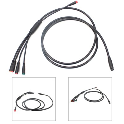
Layout
Julet Layout refers to the 3D spatial arrangement design of wiring harnesses specifically for the Julet series connectors.
The core is matching the connector body dimensions (e.g., standard models length 25-80mm, width 12-40mm) within a ±0.5mm tolerance, while addressing temperature ranges from -40℃ to +150℃, sealing levels IP67/IP6K9K, and dynamic loads (e.g., 100,000 door opening/closing cycles for door harnesses).
It requires priority verification of the connector locking mechanism (stroke 2-3mm) and the harness branch angle (≤90°), reserving a 15%-20% dynamic margin, and avoiding interference (≥1mm) with brackets/pipes through 3D simulation, ensuring assembly efficiency and long-term reliability.
Design Elements
Accurately define the connector's own dimensions
The first step in Julet connector layout is to thoroughly understand its "body dimensions." For example, the commonly used 367 series panel-mount connector has a housing length of 32mm, width 18mm, height 25mm, mounting base thickness 3mm, and lock protrusion height 4mm.
During layout, ensure sufficient peripheral operating clearance: at least 3mm on the front of panel-mount connectors (for T-wrench access to the lock), 2mm on the sides (to prevent rubbing against adjacent parts during assembly).
For cable connectors (e.g., 389 series), the rear cable outlet diameter is 12-20mm.
The harness exiting here must not have a sharp bend; the bend radius must be ≥4 times the cable diameter (6mm for thin wires, 12mm for thick wires), otherwise terminals can loosen from the pins.
Tolerance control is strict: installation hole position X/Y deviation must not exceed ±0.5mm, Z-axis (depth) ±1mm.
Exceeding this leads to installation failure or poor locking, referencing the Volkswagen VW 80101 mechanical interface specification.
How to protect the connector in different environments
Julet connectors used in different locations require adapted layouts. Near the exhaust manifold in the engine bay, ambient temperature can reach 150℃.
If the harness wraps the connector, a 2mm thick silicone thermal barrier must be inserted in between to keep the surface temperature below 125℃.
In damp areas like the chassis, the axial misalignment between the connector seal lip and the harness crimp area must be controlled within ±0.3mm tolerance, otherwise water ingress along the gap invalidates the IP67 rating.
In high-vibration areas (e.g., commercial vehicle chassis), add L-shaped metal brackets on both sides of the connector, 1.5mm thick, fastened with M4 bolts, torque 3-4N·m, to prevent loosening from vibration.
Don't make assembly difficult for workers
The angle between the connector's cable exit direction and the harness trunk should ideally be ≤45°, avoiding hard 90° bends.
The branch point should be 50-100mm from the connector port. Too close causes stress concentration; pulling during mating can damage terminals.
Place a laser-marked label near each connector, e.g., "J-01-F" (J=Julet, 01=number, F=Front compartment), 20mm from the port. The production line scanner identifies the installation location instantly.
Separate signal wires to prevent interference
Julet connectors often mix power and signal lines; layout must prevent interference. High-speed signals (e.g., CAN FD, 5Mbps) must use twisted pairs.
Spacing from power lines (>5A current) should be ≥100mm. When crossing, routes must be perpendicular, not parallel.
Shielded wire grounding is specific: shield single-point grounded, ground point ≤50mm from the Julet connector port, using 0.75mm² yellow/green wire directly to the chassis ground point.
Spacing between low-frequency analog signals (e.g., temperature sensors) and high-speed lines should be ≥30mm, referencing ISO 11452-2 immunity standard, crosstalk must be < -30dB.
Secure it, but don't overtighten
Place a tie on the main trunk every 200-300mm, using 2.5mm wide nylon ties (temperature resistant -40℃ to 125℃). Avoid leaving marks when tying.
At the connector rear, first wrap the harness with spiral wrap (pitch 15-20mm), then sleeve with convoluted tubing for double protection against abrasion.
For moving parts (e.g., door harness), the total harness length for the Julet connector should be 15%-20% longer than the static length.
After 100,000 open/close cycles, tension should not exceed 5N, otherwise the lock will gradually disengage.
Avoid collisions with other components
Use CATIA for 3D simulation during layout. Maintain a 1cm clearance around the Julet connector from brackets, fuel lines, and harness clips.
For example, for a Julet 367 connector in the front bay harness, if there's an A/C line (diameter 20mm) nearby, the minimum distance should be ≥10mm.
Spacing between adjacent connectors (e.g., a TE AMPSEAL next to it) should be ≥30mm to prevent tool interference during mating.
Do not weld fixed brackets directly below the connector; leave a 5mm gap for bolt access during future connector replacement.
Clear marking prevents misinstallation
Attach a QR code label to the end of each Julet connector branch harness, containing the connector model (e.g., 367-12-08), corresponding circuit number (e.g., ECU_A_03), and assembly station number.
Place the label 50mm from the port, using high-temperature PET material (resistant to 150℃). This can reduce production line scanning error rates below 0.1%.
Mark the main trunk every 500mm with a colored stripe (e.g., red for front bay, blue for chassis), corresponding to the Julet connector marks, allowing workers to identify the route at a glance.
Quantitative Standards
What installation position deviation is acceptable?
When installing a Julet connector onto the vehicle body, position deviation has clear numbers. For panel-mount connectors (e.g., 367 series) installation holes, X/Y direction (left/right, front/back) deviation max ±0.5mm, Z direction (depth) max ±1mm.
What happens if exceeded? E.g., 0.6mm deviation in X may prevent the lock from engaging, requiring force; 1.2mm deeper in Z may cause the connector face to protrude, rubbing against interior trim causing noise.
For cable connectors (e.g., 389 series), the rear cable outlet must align with the harness branch, deviation ≤1mm, otherwise the harness kinks, stressing the terminals.
Installation torque is also specified: panel-mount uses M3 bolts torqued to 2-3N·m, cable mount base uses M4 bolts torqued to 3-4N·m. Insufficient torque risks vibration loosening; excessive torque may strip threads.
What bend radius is safe for the harness?
The harness exiting the Julet connector must not be sharply bent. Bend radius is calculated based on wire diameter. Thin wires (conductor area ≤1.5mm²) radius ≥6mm (4x diameter), thick wires (≥2.5mm²) radius ≥12mm (also 4x).
E.g., AWG22 wire (diameter 0.64mm) radius ≥2.56mm, but practically use 6mm for safety; AWG16 wire (diameter 1.29mm) radius ≥5.16mm, use 12mm.
This is based on the IPC/WHMA-A-620 cable standard. Insufficient bending causes terminals to pull out, increasing contact resistance and causing intermittent signals.
Test data: Harness with 5mm bend radius showed terminal displacement 0.2mm after 50 mating cycles, poor contact rate increased to 5%; radius 12mm harness showed displacement 0.05mm, poor contact rate <0.1%.
How much extra length for moving part harnesses?
For moving parts like doors, hoods, tailgates, the harness needs extra length. After calculating the static length, add 15%-20% to the total length.
E.g., door harness static length 500mm, dynamic length should be 575-600mm. Why this number? Referencing 100,000 cycle fatigue test: with 10% margin, tension reached 8N after 80,000 cycles, lock began to loosen; with 20% margin, tension remained ≤5N (SAE J1113 vibration test allowable limit).
How to add margin? Near the connector branch point, form a small loop (diameter 30-40mm), avoiding a tangled bundle. Testing showed loops smaller than 20mm diameter stored stress, causing harness jacket cracks after 100,000 cycles; loops over 40mm were fine.
How far should shielded wire ground be from the connector?
High-speed signal lines (CAN FD, LIN) use shielded wires; grounding should be close to the Julet connector.
Shield single-end grounded, ground point ≤50mm from the connector port, using 0.75mm² yellow/green wire directly to chassis ground (resistance ≤0.1Ω).
Based on ISO 11452-2 EMI immunity standard: spacing over 50mm allows high-frequency interference (e.g., motor noise) to couple in, increasing CAN signal bit error rate from 10⁻⁹ to 10⁻⁶ (1 error in 100,000 frames).
When routes cross, shielded and power lines must be perpendicular, not parallel. Parallel runs over 10cm cause crosstalk exceeding -30dB (qualification limit is < -30dB).
E.g., CAN line (5Mbps) parallel to power line (10A) for 15cm, crosstalk -25dB, occasional packet loss; perpendicular routing, crosstalk -40dB, no issue.
What tie density is appropriate?
Harness fixation with ties depends on location. Main trunk (thick main harness): tie every 200-300mm, using 2.5mm wide nylon ties (temp -40℃ to 125℃).
Branch lines (to small components): tie every 150-200mm. Avoid overtightening: harness jacket deformation ≤0.5mm. Exceeding this abrades the insulation.
Test data: Tie spacing 250mm, vibration 5-2000Hz (5g acceleration) for 5 hours, harness displacement 2mm; spacing 400mm, displacement 5mm, potentially contacting adjacent fluid lines.
For moving part harnesses, use sliding-type ties (with barbs but not locked), allowing harness to telescope, not standard rigid ties.
How to control temperature in high-temperature areas?
Near the exhaust manifold (150℃) in the engine bay, cooling is needed around the Julet connector.
Insert a 2mm thick silicone thermal barrier (thermal conductivity 0.2W/m·K) between the harness and connector, keeping surface temperature below 125℃.
Tested without barrier: connector surface at 130℃ caused seal (silicone rubber) hardness to increase from 60 Shore A to 75 Shore A, elasticity decreased, IP67 seal failed. With barrier, surface 118℃, seal hardness stable at 62 Shore A.
Barrier size should be 5mm larger than the connector (each side), fully covering the metal contact area.
What seal misalignment causes leakage?
In damp areas (chassis, door bottom), the axial misalignment between the Julet connector seal lip and the harness crimp area must be ≤±0.3mm.
0.4mm misalignment allows water seepage; IP67 test (1m depth, 30 minutes) will show internal moisture.
How to check the seal? Use a 0.1mm feeler gauge; if it fits, it's out of tolerance. During terminal crimping, wire strip length should be 6-8mm. Too long interferes with the seal lip; too short compromises sealing.
E.g., 5mm strip length, seal lip lifted 0.2mm by the wire, water ingress after immersion; 7mm strip length, properly engaged by the seal, no ingress.
Where to place markers to prevent misinstallation?
Mark each Julet connector branch harness. Laser mark 20mm from the port, containing model (e.g., 367-12-08), circuit number (ECU_A_03), station number (ST-05), font height 1.5mm (scannable by production line scanner).
Use high-temperature PET labels (resistant to 150℃), attach to convoluted tubing, not directly on the harness jacket (adhesive residue).
Mark the main trunk every 500mm with a colored stripe: red for front bay, blue for chassis, green for doors, corresponding to connector marks.
Misinstallation data: without marks, workers installed by feel, error rate 3%; with marks, reduced to 0.1%.
How long must the vibration test last?
After harness installation, perform vibration test per SAE J1113 standard: frequency 5-2000Hz, acceleration 5g, duration 5 hours.
Measure what? Julet lock torque attenuation ≤10% (initial torque 3N·m, post-test ≥2.7N·m), connector terminal displacement ≤0.1mm.
E.g., a vehicle chassis harness showed post-vibration lock torque of 2.5N·m; inspection revealed a cracked bracket weld. After reinforcement, torque held at 2.9N·m.
What numbers to look for in simulation?
Use ANSYS for thermal-mechanical coupling simulation. Key numbers for Julet connectors:
-
Seal compression: Initial (new) 80%, maintaining 70%-90% at high temperature (85℃). Below 70%, seal fails.
-
Terminal contact pressure: ≥1N (for CAN lines). <1N results in contact resistance >5mΩ, signal attenuation.
-
Vibration stress: Connector housing stress ≤50MPa (PA66 GF30 tensile strength 120MPa). Exceeding causes cracking.
Use HFSS for high-frequency crosstalk analysis: CAN line near-end crosstalk < -30dB, far-end < -40dB. If exceeded, add ferrite beads. After simulation passes, physical test data deviation is typically ≤10%.
Layout Implementation Steps
First, clarify the components to be used
Obtain the 3D models of the Julet connectors, e.g., 367 series panel-mount (L32mm, W18mm, H25mm, with 2mm thick lock), 389 series cable-mount (rear outlet diameter 12-20mm). Models must include seals, lock mechanism details.
Use the vehicle/equipment CAD model in CATIA V5 format, clearly labeling obstacle coordinates – e.g., front bay A/C line (diameter 20mm, position X=450mm, Y=300mm), chassis exhaust pipe (150mm from ground).
Circuit diagrams must detail each wire's signal type (CAN FD 5Mbps, LIN 19.2kbps, power 12V/10A), wire gauge (AWG22 thin, AWG16 thick), current load (fuse rating 5A/10A).
Draw the preliminary route using 3D software
Open CATIA Harness Design or E3.series, first route the main trunk. Prefer paths along body longitudinal beams where existing clip slots exist (spacing 200-300mm, width 5mm), easier than forcing through sheet metal holes.
Julet connector port orientation should face the assembly station – e.g., for cockpit harness 367 panel-mount connector, opening faces the instrument panel side (deviation ≤15°), so workers don't need to crawl under the seat to plug.
Cable-mount 389 connector rear exit direction should form an angle ≤45° with the main trunk. Steeper angles cause sharp bends.
After the initial path, use the software's "auto-obstacle avoidance" to scan for potential interferences with brackets and fluid lines.
Simulate opening/closing for moving parts
For moving components like doors, hoods, tailgates, the harness needs margin. Use CATIA DMU Kinematics module to simulate door motion over 100,000 cycles (open angle 0° to 90°, speed 2 sec/cycle).
Set the minimum distance between the Julet connector (e.g., door-mounted 389 cable type) and the hinge to ≥10mm to avoid contact at full open angle.
Add 15%-20% dynamic margin: static length 500mm becomes 575-600mm dynamically. Form a small loop (diameter 30-40mm) at the branch point (too small stores stress, too large consumes space).
Use the software's "force sensor" to measure tension throughout the cycle ≤5N (SAE J1113 vibration test limit). If exceeded, increase margin by another 5%.
Refine details for smoother harness routing
After the preliminary route passes simulation, refine details. Use spiral wrap (pitch 15-20mm, outer diameter 2mm larger than harness) for branch harnesses, saving space compared to straight wrapping.
Spacing between high-voltage harnesses (>60V, e.g., battery positive) and Julet low-voltage connectors (e.g., 367 series 12V) should be ≥100mm.
Crossings must be perpendicular (parallel runs over 10cm cause crosstalk > -30dB).
Clearly label fixation point coordinates: main trunk tie every 250mm (2.5mm wide nylon), record position as X=123.4mm, Y=567.8mm. Tooling fixtures position based on this, error ≤0.5mm.
Use laser marking 20mm from the Julet port, content "J-01-F" (J=Julet, 01=number, F=Front bay), font height 1.5mm (scannable by production line scanner).
Perform a virtual trial to identify issues
Use ANSYS for thermal-mechanical coupling simulation: With a 2mm thick silicone thermal barrier on the Julet connector surface, in a 150℃ engine bay environment, the surface temperature is reduced to 118℃.
Seal compression initial 80%, maintained at 72% at high temperature (below 70% seal fails).
Use HFSS for high-frequency crosstalk analysis: CAN FD line (5Mbps) parallel to power line (10A) shows crosstalk -25dB (exceeds -30dB qualification). Changing to perpendicular routing reduces crosstalk to -42dB.
Vibration simulation per SAE J1113 (5-2000Hz, 5g acceleration): connector housing stress 48MPa (PA66 GF30 tensile strength 120MPa, safe).
Build a prototype and test it rigorously
Build a 1:1 prototype according to the 3D model, using the same materials as mass production (harness jacket PVC, temp -40℃ to 105℃; ties nylon 6, temp -40℃ to 125℃).
Vibration test: Mount on shaker, 5-2000Hz sweep for 5 hours, measure Julet lock torque – initial 3N·m, post-test 2.9N·m.
Immersion test IPX7 (1m depth, 30 minutes), disassemble to check for internal moisture (seal lip misalignment ≤0.3mm).
Time the assembly: Installing one 367 panel-mount connector, from picking up the harness to locking, target ≤8 minutes (pre-optimization was 12 minutes).
Misinstallation rate: Out of 100 prototypes, using markers and scanners, zero misinstallations (pre-marking had 3 errors).
Avoid conflicts with other components
During layout, coordinate with three types of components. Spacing between adjacent connectors (e.g., nearby TE AMPSEAL 23Pin) ≥30mm to prevent tool interference during mating.
Use L-shaped metal brackets (thickness 1.5mm, length 40mm) welded on both sides of the Julet connector, fastened to the body longitudinal beam with M4 bolts (torque 3-4N·m).
Use heat shrink tubing (shrink ratio 3:1, inner diameter 1mm larger than harness) sleeved 10mm before the Julet port, covering the crimped terminals for abrasion protection.
Mark the main trunk every 500mm with colored stripes (red front bay, blue chassis), corresponding to Julet marks for easy worker identification.
Specs
Julet Specs are the quantified technical specifications for Julet connectors and integrated wiring harnesses.
They define models (e.g., M-Series/X-Series), terminal crimp tolerances (±0.05mm), temperature resistance (-40℃ to +125℃), waterproofing (IP6K9K), vibration (20-2000Hz/15Grms), and over 200 other parameters, referencing standards like IPC/WHMA-A-620 Class 3 and MIL-STD-202G.
They set thresholds for continuity/withstand voltage/salt spray (500h) tests, ensuring a 0.01% defect rate and supporting high-reliability integration.
Physical Specifications
What are the connectors made of?
Taking the common M-Series as an example, the housing uses PA66 GF30 (Nylon 66 with 30% glass fiber).
This material is impact-resistant (Izod notched impact strength ≥80 kJ/m²), oil-resistant (no swelling after 72h immersion), remains unbreakable when frozen stiff at -40℃, and doesn't deform when heated soft at 125℃. Housing wall thickness is 1.2~2.0mm.
The lock slot depth is 0.8mm (tolerance ±0.1mm), ensuring a tight, rattle-free fit with the rear housing when locked.
Keying directions are A/B/C/D types, using protrusions and recesses to prevent mis-mating. For example, Key A protrusion height is 0.5mm, corresponding to a socket recess depth of 0.45~0.55mm (Julet TM-102 standard).
Total connector height ranges from 25mm (2-pin) to 60mm (12-pin). Width increases with pin count; a 12-pin M-Series is 28mm wide, 4mm wider than an 8-pin version, providing enough finger grip space.
How are terminals installed?
Terminal crimping is a precise task in physical specs. Julet terminals are divided into crimp type (most common) and insulation displacement type. Crimp types are further divided into 8 grades by wire gauge from 0.13~6mm². Taking the terminal for 0.5mm² wire as an example:
-
Crimp height must be controlled at 1.25±0.05mm (measured with 0.01mm precision micrometer). Too high causes poor contact (resistance >5mΩ), too low breaks the strands (rejection if breakage rate >3%).
-
Crimp temperature 260±5℃ (calibrated with IR thermometer), heating time 0.3~0.5 seconds, ensuring the copper core is welded firmly to the terminal tab without melting the insulation.
-
After crimping, perform cross-section analysis (sample 5 per batch), check if core wire deformation is 70%~80% (Julet CP-101 standard), and insulation retention length is 0.8~1.2mm (too long risks touching the terminal tab, too short risks leakage).
Pull test per MIL-STD-1344: For 22AWG wire with 0.5mm² terminal, use a push-pull gauge at 50mm/min speed until break – pass criteria ≥80N, and the break must be in the wire (terminal not stripped).
What are the considerations for wire gauge, insulation thickness, and printing?
Wires and terminals must be paired; Julet Specs specify clearly:
-
Cross-Sectional Area: M-Series uses 0.13~2.5mm² (current carry 1~15A), X-Series (high current) uses 2.5~6mm² (10~60A), Q-Series (aviation light load) uses 0.13~1.0mm² (2~5A).
-
Insulation: Normal environment uses XLPE (cross-linked polyethylene), temp resistance 150℃, wall thickness 0.4mm; high-temperature areas (e.g., near engine) use Silicone rubber, temp resistance 200℃, wall thickness 0.5mm (low expansion rate, won't crush terminals).
-
Printing: Print wire number (black background, white text), color code (e.g., RD=Red), and Julet logo every meter. Font height 2mm (using UV ink, doesn't fade after 500h exposure). Start printing 100mm from the wire end.
Multi-core cable outer jacket uses PVC or TPE. PVC is cheaper ($0.8/m) but brittle at low temp (cracks at -20℃). TPE is more expensive ($1.5/m) but resistant to -40℃.
Jacket wall thickness is 1.5mm. Printing content is the same as single-core, plus "JULET CERTIFIED" anti-counterfeit mark.
Don't forget the rear housing, seal plug, and locking mechanism
The rear housing isn't just for show. The waterproof type uses EPDM rubber (Ethylene Propylene Diene Monomer), Shore A hardness 70, compression set ≤20% (tested at 125℃×72h), installed at the connector rear to block water.
Seal plug aperture is sized according to wire diameter: 0.5mm² wire uses Φ1.8mm hole. After insertion, the gap should be <0.1mm.
Locking mechanisms are of two types: latch type (single/double lock) and screw type. Latch type uses POM plastic (Polyoxymethylene), lock retention force ≥30N (EIA-364-04 test).
Double lock provides an extra safety feature compared to single lock, less prone to loosening under vibration. Screw type uses M3 stainless steel screws, torque 0.8±0.1N·m (using torque screwdriver). Too loose causes rattling; too tight strips threads.
Comparison of different Julet series' physical builds
|
|
|
|
|
|
|
|
|---|---|---|---|---|---|---|
|
|
|
|
|
|
|
|
|
|
|
|
|
|
|
|
|
|
|
|
|
|
|
|
Q-Series with LCP material is lightweight (density 1.4g/cm³, 20% lighter than PA66), used in aircraft for weight reduction, but expensive (housing unit cost is 3x M-Series).
How to securely install fasteners and labels?
Use ties to secure Julet connectors in the harness. Ties use PA66 (same material as housing), width 2.5mm, tensile strength ≥50N (breaking force).
Fixation point spacing ≤300mm (per ISO 16750 vibration standard). Place one tie on each side of the connector, fastened to a metal bracket (plastic brackets break easily from vibration).
Labels use PET material (polyester film), temperature resistant -40~150℃, size 25×15mm. Print "JULET PN:12345", "DATE:20240520", "QTY:1". Use acrylic adhesive, leaving no residue upon removal (adhesion ≥2N/cm per PSTC-101 test).
Label position is directly above the connector, 50mm from the port end. Avoid placing on bends (will wear off).
Electrical Specifications
What voltage/current can it really handle?
Rated voltage is divided into two tiers: ordinary industrial use 250V AC/400V DC (M-Series), high-voltage scenarios (e.g., EV battery packs) 600V DC (X-Series).
Continuous current depends on wire gauge and ambient temperature – Julet TM-301 manual provides derating curves: 0.5mm² wire carries 5A at 25℃ ambient, derates to 4A at 70℃, and only 3A at 95℃. 2.5mm² wire is more robust, carries 15A at 25℃, still 12A at 70℃.
Surge current is a short-term inrush, e.g., during motor start. Specs stipulates that surge must not exceed 3 times the rated current for 10ms (0.5mm² wire rated 5A, surge max 15A).
A German automaker using X-Series 6mm² wire for battery connection, designed per this surge value, showed terminal temperature rise of only 8℃ (measured with IR camera) at startup, not exceeding the 125℃ upper limit.
How to reliably test insulation and withstand voltage?
Insulation quality is determined by two numbers: insulation resistance and withstand voltage.
Insulation resistance is measured with a megohmmeter, applying 500V DC between wires, and between wire and housing. Resistance ≥100MΩ is qualified (reference UL 1977).
For shielded wires, insulation resistance between shield and conductor must be higher, ≥500MΩ (to prevent signal crosstalk).
Withstand voltage test is more severe, per IEC 60512-2: Apply AC 1500V (or DC 2120V) between wires, AC 2250V between wire and housing, for 1 minute, no breakdown allowed.
Post-test insulation resistance drop must not exceed 20% – e.g., 100MΩ before test, at least 80MΩ after.
Data from a US industrial equipment maker: testing to this standard reduced withstand voltage failure rate from 0.8% to 0.1%, mainly by eliminating batches with minor insulation bubbles.
How to prevent EMC interference?
Electromagnetic Compatibility (EMC) relies on shielding and grounding. Julet shielded connectors are of two types: braided shield (coverage ≥85%) and foil shield (overlap ≥90%).
Transfer impedance is the key indicator for shielding effectiveness. Braided shield ≤5mΩ/m (at 1MHz), foil shield ≤10mΩ/m (MIL-STD-461 Method RS103 test).
Grounding method matters: Single-point grounding suits low frequency (<10MHz), avoiding ground loops. Multi-point grounding is for high frequency (>100MHz), shortening ground paths.
E.g., aviation equipment using Q-Series connectors, shield grounded at both ends with 0.5mm² ground wire to chassis,Measured transfer impedance 4.2mΩ/m, radiated emissions 20dB lower than unshielded version (measured with spectrum analyzer).
What are the considerations for high-frequency signal routing?
Data harnesses (e.g., CAN bus, Ethernet) must control signal integrity. Characteristic impedance must match: CAN bus uses 120Ω, Ethernet uses 100Ω differential.
Measure with TDR (Time Domain Reflectometer), deviation must not exceed ±10%.
Insertion loss is signal attenuation, ≤0.5dB at 100MHz (measured with network analyzer). Crosstalk (interference between adjacent lines) ≤-40dB.
A robot company using Julet X-Series for Gigabit Ethernet harness, selecting shielded twisted pair per this standard, reduced bit error rate from 10⁻⁶ to 10⁻⁹, extending transmission distance from 50m to 100m.
Environmental & Reliability
How long can it withstand temperature cycling?
Per IEC 60068-2-14 standard, temperature cycling tests are of two types: Conventional (-40℃~+125℃, 500 cycles) and Extreme (-55℃~+150℃, 1000 cycles).
Each cycle includes: Soak at -55℃ (or -40℃) for 2 hours → Heat to +150℃ (or +125℃) soak 2 hours → Cool back to start. Thermocouples attached to terminals monitor temperature throughout.
Post-test, check three numbers: Contact resistance change ≤5mΩ (measured by 4-wire method), Insulation resistance ≥80% of initial value (megohmmeter 500V DC range), Housing free of cracks (inspected with magnifier).
A Nordic automaker tested Q-Series (aviation grade) at -40℃: Terminal insertion/extraction force changed from initial 30N to 33N (change ≤10%), no plastic brittleness cracking occurred.
A connector with standard PA66 housing, under same conditions, showed insertion force spike to 50N at -40℃, and lock fracture after 50 cycles.
High-temperature test is stricter: After 72 hours at 125℃, terminal plating (tin/gold) must not oxidize/discolor (compared with color chart), insulation at crimp must not soften (Shore hardness maintained ≥80A).
X-Series (for EVs) at 150℃ ambient, measured with IR camera, showed max terminal temperature 102℃ under full load, below the 125℃ upper limit (Julet TM-401 standard).
Will dampness and mold cause failure?
Damp heat test simulates rainy seasons or high-humidity workshops, per IEC 60068-2-78: 85% Relative Humidity (RH), 85℃ environment, duration 1000 hours.
Post-test inspection: Terminal surface free of green corrosion (copper oxidation), insulation jacket free of blisters (water absorption swelling), no mold spots removable by alcohol wipe (ASTM D3276 standard).
Data from a Southeast Asian industrial equipment maker: Using M-Series connectors, prior to damp heat testing, field failure rate was 12% (mainly due to terminal oxidation). After 1000h damp heat test per Specs, failure rate dropped to 1.5%.
The key is terminal plating thickness – Tin plating ≥3μm (standard is 2μm), Gold plating ≥0.5μm (for frequent mating scenarios), resistant to moisture penetration.
Condensation test is more realistic: At 25℃, 95% RH environment, condensation forms on connector surface for 24 hours. Insulation resistance must remain ≥100MΩ (reference IPC-TM-650 2.6.3.3).
Will vibration and shock cause loosening?
Vibration tests include sinusoidal sweep and random vibration. Sinusoidal sweep per MIL-STD-202G Method 214: Frequency 20-2000Hz, acceleration 15Grms, vibrate 8 hours per X, Y, Z axis (total 24 hours).
Random vibration per ISO 16750-3: PSD (Power Spectral Density) 0.04g²/Hz, total RMS acceleration 10Grms, duration 10 hours.
Post-test checks: Connector not loose (recheck locking force with torque wrench, latch type ≥30N, screw type ≥0.8N·m), terminals not displaced (CMM measures pin position, tolerance ±0.1mm), contact resistance change ≤5mΩ.
Case from a German construction machinery maker: Using X-Series for hydraulic valve connection, after testing to this standard, field life under vibration (excavator operation) extended from 6 months to 2 years, eliminating signal interruptions from loosening.
Shock test is more severe: Half-sine shock, acceleration 50G, pulse width 11ms, 3 shocks per X, Y, Z axis. Post-test: Housing crack-free, terminals unsoldered (X-ray inspection).
Can it withstand salt spray and acid rain?
Salt spray test simulates coastal or winter salt-sprinkled roads, per ASTM B117 standard: 5% Sodium Chloride solution, 35℃ environment, continuous spray.
Conventional test: 500 hours. Severe test: 1000 hours (e.g., marine, aviation). Post-test, inspect terminals under magnifier: No white/green corrosion (Copper Chloride/Cuprous Chloride), contact resistance ≤120% of initial value (MIL-STD-1344).
A North American automaker using X-Series for battery pack connection: After 1000h salt spray, terminal tin plating slightly darkened (normal oxidation), resistance increased from 2mΩ to 2.3mΩ (change 15%.
Exceeds Specs' 20% red line? No, Specs allow ≤20%, so qualified). Using standard zinc-plated terminals would result in complete rusting at 500h, resistance soaring above 50mΩ.
Acid rain test uses pH 3.0 sulfuric acid solution (simulating industrial pollution), spray for 24 hours, housing shows no corrosion signs (test residual liquid with pH paper, neutral).
Are oil and water exposure problematic?
Liquid contact tests involve three types: Engine oil (SAE 10W-40), Coolant (ethylene glycol base), Water (with detergent). Per ISO 20653 standard, after 24h immersion:
-
Outer jacket shows no swelling (volume change ≤5%, measured by water displacement);
-
No oil seepage at terminal crimp (wipe with acetone, no oil residue);
-
Insulation resistance ≥100MΩ (coolant can be conductive, focus test).
Case from a French agricultural machinery maker: Using M-Series for engine sensors, selecting oil-resistant PVC jacket per Specs (72h oil immersion, volume increased only 3%), showed no cracking after 1 year in field; previous standard PVC swelled and exposed wires in 3 months.
Environmental endurance comparison of different Julet series
|
|
|
|
|
|
|
|---|---|---|---|---|---|
|
|
|
|
|
|
|
|
|
|
|
|
|
|
|
|
|
|
|
|
|
Q-Series has the highest temperature resistance (-65℃~175℃), used near aircraft engines. X-Series salt spray test 1000h, withstands coastal or de-icing salt environments.
What test tools and pass/fail criteria are used?
Test environmental reliability with these tools:
-
Environmental Chamber (ESPEC PL-3): Temperature control ±1℃, Humidity ±3%RH;
-
Vibration System (LDS V964): Frequency 5-3000Hz, Acceleration 0-50Grms;
-
Salt Spray Chamber (Q-FOG CCT-1100): Spray rate 1-2ml/80cm²/h;
-
Infrared Thermal Imager (FLIR E95): Temperature accuracy ±2℃.
Pass/Fail criteria are strict: Post-temperature cycle resistance change ≤5mΩ, post-vibration locking force meets standards, post-salt spray no visible corrosion. Data from a Japanese harness maker: Following this Specs for environmental testing reduced mass-production harness field failure rate from 8% to 0.3%, mainly by screening out batches unable to withstand the environment early.
