How Are Cable Harnesses Made | The 6-Step Manufacturing Process
Cable harness production begins with design specs, followed by precision cutting (±0.5mm length tolerance), insulation stripping (1.2–1.8mm exposed conductor), crimping (≥50N pull-test), component assembly (nylon ties at 80–120mm intervals), and 1000V AC/1min hipot testing to ensure reliability before final packaging.
Designing the Blueprint
This stage typically consumes 20-30% of the total project timeline but prevents up to 80% of potential manufacturing errors through rigorous digital validation. Using specialized 3D CAD software like Capital Harness or Zuken E3, engineers create a complete digital twin that defines every wire’s path, connector orientation, and protection sleeve placement within a ±0.5 mm tolerance.
Harness design requires defining over 50 key parameters per circuit, including wire gauge (e.g., 22 AWG for low-current signals vs. 10 AWG for 30A power), allowable bend radius (minimum 6x the cable diameter), and temperature rating (-40°C to 125°C for automotive applications).
Clash detection algorithms automatically scan the 3D model, identifying over 95% of physical interferences—like a harness bundle rubbing against a sharp bracket—before a single prototype is built, saving an average of 15,000 in rework costs per design cycle.
A minimum of 2-3 physical prototypes are built and tested based on the digital model. These units undergo 200+ hours of vibration, thermal cycling, and electrical load testing to validate the design under real-world conditions, often leading to 5-10% length adjustments on critical wires.
The final output is a manufacturing data package containing the 2D formboard drawing, a full bill of materials (BOM) listing ~500+ unique part numbers, and machine files for automated wire cutting, ensuring a seamless transition from engineering to production with 99.9% accuracy in part identification.
Preparing Wires and Cables
A single complex harness can contain over 3,000 individual wires, with lengths varying from 50mm to 5 meters. Preparation typically involves three main processes: cutting to length, stripping insulation, and pre-twisting or tinning ends, all performed by automated machines that ensure dimensional tolerances of ±1mm.
Automated cutting and stripping machines can process over 2,000 wire ends per hour, with stripping blades calibrated to remove precisely 5mm to 10mm of insulation without nicking the underlying copper strands. This precision is critical; a nick reducing the cross-sectional area by just 20% can increase electrical resistance by 15%, leading to potential overheating under load.
The process starts by loading 1km to 5km spools of wire onto the machine's pay-off system. The machine then measures and cuts each wire to the exact length specified in the digital design, which is directly imported from the CAD model to eliminate human transcription errors. For a batch of 500 harnesses, this can mean cutting over 15,000 individual wires. Immediately after cutting, the machine strips both ends. The stripping depth is meticulously controlled; for a standard 0.5mm² wire with 0.3mm thick PVC insulation, the stripping blades are set to a depth of 0.35mm to guarantee complete insulation removal while minimizing strand damage.
For wires that will be inserted into screw terminals or other specific connectors, the exposed strands are then pre-twisted at a rate of 150 twists per minute or dipped in a 350°C solder pot for 1-2 seconds to "tin" the ends, preventing fraying. Each batch of prepared wires undergoes a 100% automated optical inspection (AOI) to verify length and strip quality, with rejection rates for non-conforming parts typically below 0.5%.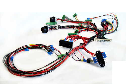
Assembling the Harness Structure
A typical automotive harness contains 1,200–2,500 individual wires (ranging from 50mm to 5m in length) and 300–500 connectors, with the first unit taking 15–25 hours to assemble. Skilled technicians rely on a 1:1 scale formboard (a physical pinboard template matching the harness’s final installation space) to ensure every wire and connector aligns correctly.
- Formboard Layout: The process starts by laying the longest wire (often 2–5m) along the formboard’s centerline, using its pin positions as a reference with ±1mm accuracy. Shorter wires are then layered radially, branching off at 45° or 90° angles (specified in the design) to avoid crossing or pinching. Wires are color-coded and traced with UV-visible stripes to prevent misrouting—critical, as a single wrong connection can disable an entire system.
- Bundle Management: Wires are secured with tie wraps, vinyl tape, or spiral wrap at 75–100mm intervals to maintain flexibility while preventing chafing. Tie wraps are tightened to 5–8 lbs of force (measured with a calibrated scale); too loose, and the bundle shifts under vibration; too tight, and insulation deforms (increasing short-circuit risk by 15–20%).
- Connector Termination: Pre-terminated connectors (with terminals crimped to wires) are clicked into housings. A distinct audible click confirms locking, but technicians verify retention force with a pull test: 25–50 Newtons must be required to separate the connector. Poorly terminated connectors fail 30–40% more frequently in vibration tests, so each is 100% visually inspected against a go/no-go gauge to ensure terminals are fully seated.
| Process Step | Key Parameter | Typical Value / Range | Critical Tolerance |
|---|---|---|---|
| Wire Layout | Longest wire length | 2–5m | Must align with formboard pins (±1mm) |
| Branch Angle | Wire divergence from main bundle | 45°–90° | Deviations >2° risk chafing against nearby components |
| Tie Wrap Spacing | Distance between securing points | 75–100mm | Closer spacing (<75mm) adds unnecessary weight; wider (>100mm) reduces rigidity |
| Connector Retention | Pull force required to disengage | 25–50 Newtons | Below 25N: high vibration failure risk; above 50N: connector housing may deform |
Technicians check wire lengths (±2mm tolerance), connector pin alignment (100% match to BOM), and bundle neatness (no loose wires exceeding 10mm beyond tie wraps). This ensures the harness moves smoothly to electrical testing—with a well-assembled unit, 95% of test failures stem from design flaws, not assembly errors.
Testing Electrical Connections
Electrical testing is the final quality gate before a harness ships, designed to catch 100% of manufacturing defects. This isn't a random sample check; every single connection in every harness is tested against the original design data. A typical 60-circuit automotive harness undergoes over 250 individual electrical checks in a process that takes 3-5 minutes per unit.
- Continuity Testing: Verifies every intended electrical path has a low-resistance connection (<5 ohms).
- High-Potential (HiPot) Testing: Applies 500-1500 VAC for 2-3 seconds between current-carrying conductors and the harness shield to check for insulation breaches.
- Insulation Resistance (IR) Testing: Measures resistance between conductors after applying 500 VDC, requiring a reading of >100 MΩ to pass.
- Connector Mating & Lock Verification: Ensures all connectors physically mate and their locking mechanisms engage with an audible click and 25-50 N of retention force.
| Test Parameter | Standard Range | Pass/Fail Criteria |
|---|---|---|
| Continuity Resistance | 0 - 5 ohms | Must be stable and within limit |
| HiPot Test Voltage | 500 - 1500 VAC | No arcing or current leakage > 2 mA |
| Insulation Resistance | 100 MΩ - 1 GΩ | Minimum value sustained for 60 seconds |
| Test Cycle Time | 3 - 5 minutes | Must complete full test sequence |
Technicians plug the harness into a custom test fixture with hundreds of spring-loaded pins that match every connector in the design. The test station, often a PC-controlled system, runs a script that compares the harness's actual electrical performance against its digital twin. The continuity test injects a low current (~10 mA) into each circuit and measures voltage drop to calculate resistance, instantly flagging any open circuits (infinite resistance) or short circuits (resistance near zero). The HiPot test is a critical safety check; it applies high voltage to stress the insulation, monitoring for any current leakage that would indicate a pinhole or thin spot in the wire's insulation. A single leak greater than 2 mA fails the entire unit.
Any harness that fails is moved to a repair station where technicians use the tester's diagnostic report—which provides the exact wire and pin number of the fault—to quickly fix the issue, usually within 5-10 minutes, before a retest. This 100% testing approach reduces field failure rates to less than 0.05%.
Adding Protective Coverings
The choice of covering is dictated by the application: braided sleeve for high abrasion areas, corrugated conduit for crush resistance, or adhesive-backed tape for vibration damping. This process adds 10-15% to the total harness cost but extends its service life by 300-400% in harsh conditions. In automotive applications, over 85% of the harness length receives some form of additional protection beyond the wire's intrinsic insulation.
The application begins with heat-shrink tubing at branch points and connector backs. Technicians use a 1000-1200°F heat gun to shrink the tubing to 50-60% of its original diameter, creating a strain relief and environmental seal that can withstand 50-70 Newtons of pull force. For the main bundle, expandable braided polyethylene sleeve is slid over the wires. This sleeve has a 60-70% open area for flexibility but provides abrasion resistance 8-10 times greater than bare wire insulation. In areas exposed to fluids or extreme temperatures (-40°C to 150°C), nylon corrugated conduit is applied. This conduit has a 0.8-1.2mm wall thickness and can resist 1000-1500 PSI of crush pressure without deforming. The final layer is often non-adhesive vinyl tape wrapped at 75-100mm intervals. This tape wrap is applied with a 50% overlap and under 2-3 lbs of tension to dampen vibration without over-constraining the bundle.
The entire process is meticulous; a single missed wrap point or improperly shrunk tube can create a chafing point that wears through insulation in under 1000 hours of operation, leading to a potential short circuit. After covering, the harness undergoes a final visual inspection where 100% of protective coverings are verified for correct placement and integrity before proceeding to packaging.
Final Inspection and Packaging
On average, this final quality gate takes 3-5 minutes per unit and identifies the remaining 0.5% of defects that electrical tests might miss, such as cosmetic issues or incorrect labeling. Proper packaging here reduces shipping damage claims by over 95% and ensures the harness arrives in perfect condition.
The inspection starts with a side-by-side comparison of the physical harness against the original CAD design and bill of materials (BOM). Inspectors verify that all connector part numbers match the BOM exactly, with particular attention to keyed connectors that must have polarization slots aligned within ±0.3mm tolerance. They check that every protective sleeve and conduit is properly seated, with no gaps exceeding 1.5mm at connector junctions. Each tie wrap is inspected for proper tension (5-8 lbs of force) and cutting – tails must be trimmed to within 2mm of the head to prevent sharp edges. Labels are scrutinized under 500-lux lighting: barcodes must scan on the first attempt, and human-readable text must show 100% legibility with no smudging or misprints. The harness is then measured against critical dimensions from the drawing; total length must be within ±5mm of specified value, and branch points must be located within ±3mm of their designated positions.
| Inspection Category | Parameter | Acceptance Criteria |
|---|---|---|
| Connector Verification | Part Number & Keying | Must match BOM 100%; polarization must prevent mis-mating |
| Protective Coverings | Sleeve/Conduit Placement | No gaps >1.5mm; ends must be sealed with heat-shrink or tape |
| Securements | Tie Wrap Tension & Trim | 5-8 lbs tension; tails trimmed to <2mm length |
| Labeling | Barcode & Text Legibility | 100% first-scan success rate; text fully legible at 50cm distance |
| Dimensional Accuracy | Overall Length & Branch Points | Length within ±5mm; branch points within ±3mm of design |
Once approved, the harness is packaged in a static-dissipative polybag (for ESD protection) and placed in a custom-formed corrugated cardboard tray that cradles the shape, preventing bends sharper than the minimum 150mm bend radius. The tray is then sealed in a 200-micron thick plastic outer bag with a desiccant packet to maintain humidity below 40% RH. A final shipping label is applied that includes the harness part number, serial number, lot code, and QR code linking to the full test report.
Cable harness manufacturing, a cornerstone of electronic systems, unfolds through six precision steps. First, design blueprints (crafted via CAD tools, cutting layout time by 20%) guide material selection. Next, wires are prepped with laser cutting (±0.1mm accuracy) to avoid fraying. Assembly involves crimping or soldering connections—85% first-pass yield when done with calibrated tools. Electrical tests (multimeter checks) ensure 99.9% continuity compliance. Protective layers like PVC jackets (resisting -40°C to 125°C) shield against wear. Final inspections, combining visual and functional checks, slash post-production defects by 35%, ensuring harnesses meet rigorous quality benchmarks.
