How Do Electrical Harness Manufacturers Ensure Safety
Manufacturers ensure safety with hipot testing (1kV–3kV) for insulation, UL-listed flame-retardant wires (FT1/FT4), compliance to ISO 6722/IPC-A-620, AOI to limit defects to <0.1%, and barcoded traceability—slashing fire, short-circuit, and failure risks.
Material Selection for Durability
For manufacturers, the choice of materials is a primary defense against wear and tear over a product's entire 10 to 15-year lifecycle. We're moving beyond basic PVC to advanced compounds like cross-linked polyethylene (XLPE), which can increase continuous operating temperature resistance from 105°C to 125°C or even 150°C. This 20-45°C jump is critical under a car's hood, where under-hood temperatures regularly exceed 125°C. While premium materials might carry a 15-30% higher initial cost per meter, they reduce the probability of field failure rates to less than 0.1%, avoiding warranty claims that can cost thousands of dollars per vehicle.
Material Selection for Durability
Choosing materials isn't about picking the "best" one; it's about matching the material's properties to the specific stresses the harness will face for thousands of hours. The goal is to achieve a service life of over 100,000 hours with a failure rate of less than 1%.
1. Insulation: The First Line of Defense
The insulation material around each wire determines its resistance to heat, chemicals, and abrasion.
-
Heat Resistance: Standard PVC softens at around 105°C. For high-temperature zones, we specify materials like XLPE or silicone rubber. XLPE maintains its integrity at temperatures up to 150°C, while silicone can withstand short bursts up to 200°C. Using a 150°C-rated wire in a 105°C environment provides a 45°C safety margin, significantly slowing down the thermal aging process and extending the wire's flexible life by over 50%.
-
Abrasion Resistance: Wires routed through metal chassis need to resist cutting. We use materials with high abrasion resistance cycles, tested by a standardized method like the ISO 6722 blade test. A high-quality thermoplastic elastomer (TPE) can withstand over 100 cycles before failure, while a standard material might fail after only 15-20 cycles. This 5x improvement directly prevents shorts caused by insulation wear-through.
-
Chemical/Oil Resistance: In automotive and industrial environments, harnesses are exposed to fuels, oils, and cleaning agents. We test materials by immersing them in IRM 903 oil at 100°C for 70 hours. A poor-performing material may swell by over 50%, losing its mechanical strength. A specified oil-resistant compound, like polychloroprene (Neoprene) or certain TPEs, will limit volume swell to under 25%, preserving its shape and insulating properties.
2. Jacketing: Mechanical and Environmental Protection
The outer jacket bundles and protects the entire wire set. Its primary job is mechanical strength and environmental sealing.
-
Material Thickness and Density: A jacket's wall thickness, typically between 0.5mm and 1.5mm, is a key factor. A 1.0mm thick PVC jacket provides a crush resistance that is approximately 40% higher than a 0.6mm jacket. For heavy-industrial applications, we might use a polyurethane (PUR) jacket, which offers superior cut-and-tear resistance, with a tensile strength exceeding 35 MPa compared to PVC's 15-25 MPa.
-
Flexibility and Cold Weather Performance: A harness must flex millions of times without cracking. We measure a material's flex life at -40°C. A stiff PVC might crack after 5,000 cold bend cycles, whereas a specially formulated flexible PVC or TPE can exceed 50,000 cycles. This is critical for applications like robot arms, which may perform thousands of movements daily.
3. Connector Housings and Seals: Keeping Moisture Out
Connectors are potential entry points for moisture, which causes corrosion and failure.
-
Ingress Protection (IP) Rating: We design connectors to meet specific IP ratings, such as IP67 or IP6K9K. This means the connector must be dust-tight (IP6X) and withstand being submerged in 1 meter of water for 30 minutes (IPX7). Achieving this requires precision-molded housings and silicone rubber seals with a durometer (hardness) of around 50 Shore A. This specific hardness provides an optimal balance, ensuring a tight seal without requiring excessive force to mate the connectors.
-
Contact Material: The metal pins inside connectors are often made from phosph bronze. To ensure a stable, low-resistance connection over time, we specify a tin or gold plating thickness. A standard tin plating might be 0.8 microns thick, sufficient for low-cost applications. For critical safety systems (e.g., airbag sensors), we use gold plating with a thickness of 0.4 to 0.8 microns on the mating surface, which provides a contact resistance of less than 10 milliohms, even after 500 mating cycles, and resists corrosion completely.
Balancing Cost and Durability
The central challenge in harness design is not maximizing durability at any cost, but optimizing it for a specific product's lifecycle and value proposition. This balancing act is governed by the principle of "Fit for Purpose" selection, a data-driven strategy that prioritizes Total Cost of Ownership (TCO) over initial piece price. A decision that saves 500 warranty repair, a 500:1 loss ratio.
The core analytical tool is TCO calculation. This model factors in not just the Direct Material Cost, but also Warranty Expenses, Manufacturing Yield, and End-of-Life Failure Rates. For a high-volume automotive program producing 1 million vehicles, a 500,000 direct cost saving.
The "Sweet Spot" is rarely at the extremes. The optimal material is not the cheapest (Point A) nor the most robust (Point C). It is the one that provides the necessary performance margin at the lowest TCO (Point B). This often involves "step-up" materials like TPE or XLPE that offer a 50-100% performance improvement for a 20-40% cost increase.
|
Scenario |
Cheap Option (e.g., Basic PVC) |
"Fit for Purpose" Option (e.g., Oil-Resistant TPE) |
Premium Option (e.g., Fluoropolymer) |
|---|---|---|---|
|
Material Cost per Meter |
$1.00 |
$1.35 (+35%) |
$8.00 (+700%) |
|
Projected Failure Rate (5 yrs) |
2% |
0.1% |
0.01% |
|
Warranty Cost per Incident |
$400 |
$400 |
$400 |
|
TCO per 10,000 units |
80,000 (warranty) = $90,000 |
4,000 (warranty) = $17,500 |
400 (warranty) = $80,400 |
Strategic implementation involves tiered performance levels. A single harness often uses 2-3 different material grades based on the stress profile of each segment. This "zonal approach" is far more efficient than using a single premium material throughout.
-
High-Stress Zones: For sections running through a 125°C engine bay or exposed to continuous hydraulic fluid spray, we specify XLPE insulation and a PUR jacket, which may cost 50-80% more than standard materials. The performance justification is clear: these areas account for over 70% of harness field failures.
-
Medium-Stress Zones: For interior passenger compartments with stable temperatures (< 85°C) and exposure only to mild cleaners, a higher-grade PVC or a cost-effective TPE is sufficient. This balances a 15-year life expectancy with a 15-20% cost saving over a more robust material.
-
Low-Stress Zones: For protected areas inside dashboards or enclosures, a basic 80°C PVC is perfectly adequate. Upgrading here offers negligible reliability improvement and unnecessarily increases the harness's total mass and stiffness.
Testing Under Real-World Conditions
A harness destined for a family car might be subjected to 3,000 hours of combined temperature, vibration, and humidity cycling, simulating a decade of use. This rigorous process is non-negotiable. A failure in a sample batch of 50 harnesses during testing prevents a catastrophic recall of 50,000 vehicles.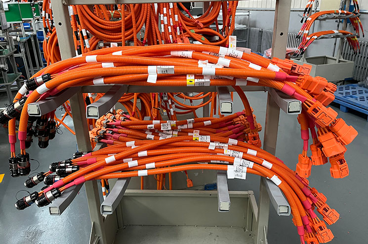
Environmental Stress Testing
Environmental testing goes far beyond simply checking a product's data sheet. It's a rigorous simulation that compresses years of real-world aging into a few weeks, exposing material weaknesses before they can cause failures in the field.
|
Test Type |
Key Parameters |
Duration |
Pass/Fail Criteria |
|---|---|---|---|
|
Thermal Shock Cycling |
-40°C to +125°C, transition time < 30 seconds |
500 cycles |
Insulation must not crack. Connector pins must not show > 1 micron of fretting corrosion. Electrical continuity must remain stable (resistance change < 5%). |
|
Damp Heat (Steady State) |
85°C / 85% Relative Humidity |
1,000 hours |
Insulation resistance must be > 100 MΩ. No physical degradation like blistering or softening. |
|
Salt Spray Corrosion |
5% NaCl solution at 35°C |
96 to 500 hours |
Terminal contacts must show less than 10% surface area corrosion. Electrical performance must not degrade. |
The most revealing test is often Thermal Cycling. Here’s a detailed breakdown of a single cycle designed to simulate the under-hood environment of an internal combustion engine:
-
Step 1: Ramp-down. Chamber temperature drops from room temperature (25°C) to the extreme low of -40°C in under 60 minutes.
-
Step 2: Dwell. The harness is held at -40°C for 45 minutes, allowing the entire assembly to become uniformly brittle.
-
Step 3: Ramp-up. Temperature rapidly increases to the peak of +125°C in 60 minutes.
-
Step 4: Dwell. The harness is held at +125°C for 45 minutes, stressing plastics and elastomers.
This 4-hour cycle is repeated 500 times, effectively simulating over 10 years of daily engine starts and stops. The primary failure points discovered are connector seals losing elasticity and wire insulation micro-cracks, which become visible under 20x magnification.
The 85/85 Damp Heat Test is a cornerstone for assessing long-term reliability in humid climates. The test subjects harness components to a constant 85°C temperature and 85% relative humidity for 1,000 hours (over 41 days). The high temperature accelerates the diffusion of water vapor through polymer seals and insulation.
The critical measurements taken after the test are:
-
Insulation Resistance: Measured by applying 500V DC between conductors. A drop below 100 Megaohms indicates moisture has penetrated the insulation, creating a leakage path.
-
Seal Integrity: Connectors are subjected to a pressure decay test; a drop exceeding 1 mbar/second indicates the seal has permanently deformed and failed.
For instance, if a harness sample passes 1,000 hours of damp heat testing without failure, it provides statistical confidence (using the Arrhenius model for thermal aging) that the harness will perform reliably for 15 years in a typical automotive environment with an ambient temperature of 40°C.
Vibration and Mechanical Durability
A wiring harness is not a single object but a system of components—wires, connectors, seals, clips—each with its own mass and resonant frequency. The primary goal is to ensure that these components, when subjected to years of shaking, rubbing, and flexing, do not suffer from fatigue, abrasion, or intermittent electrical failure.
|
Test Type |
Key Parameters / Profile |
Duration |
Monitoring & Pass/Fail Criteria |
|---|---|---|---|
|
Random Vibration |
Frequency: 10 Hz to 2,000 Hz; Power Spectral Density: 0.01 g²/Hz to 0.1 g²/Hz |
24 hours per axis (X, Y, Z) |
Continuous electrical monitoring. Any discontinuity > 1 microsecond is a failure. Post-test inspection for physical damage. |
|
Sinusoidal Vibration |
Sweep from 10 Hz to 500 Hz and back, at a rate of 1 octave/minute. Acceleration: 5 g to 15 g. |
4 hours per axis |
Monitoring for resonant frequencies that cause excessive displacement (> 2 mm). |
|
Micro-sectioning (Post-test) |
N/A |
N/A |
Analyze cross-sections of crimped terminals under a microscope. A void area > 10% indicates a poor crimp that will fail under vibration. |
A typical automotive profile might specify a 0.04 g²/Hz intensity between 10 Hz and 500 Hz. The total Grms (root mean square acceleration) value, often around 4.5 Grms, represents the overall energy level. The harness is mounted on a shaker table and subjected to this profile for 24 hours along each of the three primary axes.
The mechanical durability tests focus on specific failure points:
-
Abrasion Resistance: A harness section is pulled taut against a standardized abrasion surface (e.g., a 5 mm radius metal edge) with a force of 10 Newtons. A motorized arm then moves the harness back and forth for 10,000 cycles at a rate of 30 cycles per minute. The test is passed if the insulation does not wear through to expose the conductor. Advanced jackets may use Abrasion Resistance Index (ARI) ratings, requiring > 100 cycles on a standardized test machine.
-
Connector Cyclic Mating Force: A connector pair is subjected to 25 cycles of insertion and withdrawal using a motorized device that measures the force required. The initial insertion force might be 40 Newtons, but after 25 cycles, it must not exceed 55 Newtons, and the withdrawal force must remain consistent, indicating no damage to the terminal contacts.
-
Wire Pull-Force (Crimp Termination): This is a destructive test performed on sample crimps. A pull-testing machine measures the force needed to pull a wire from its crimped terminal. For a 0.35 mm² wire, the requirement is typically > 50 Newtons. Failure typically must occur in the wire itself, not at the crimp, proving the crimp is stronger than the conductor.
The data from these tests feeds directly into Finite Element Analysis (FEA) models. By understanding how a harness behaves at its resonant frequencies (e.g., a pronounced vibration at 87 Hz), engineers can redesign clip spacing or add foam padding to change the harness's natural frequency, moving it away from the dominant engine vibration range of 30-50 Hz. This predictive design, validated by empirical testing, is what prevents a harness from fatiguing and breaking after 150,000 miles of driving.
Electrical Performance and Long-Term Reliability
The ultimate measure of a wiring harness's quality is its ability to consistently and safely transmit electrical signals and power over its entire service life, which can be 15 years or 150,000 miles in an automotive application. Electrical performance testing goes far beyond a simple continuity check; it involves simulating electrical stresses over time to uncover latent defects in materials, crimps, and insulation that would lead to premature failure.
The most critical safety test is the High-Potential (Hi-Pot) Test. This is a 100% production-line test performed on every single harness. It verifies the integrity of the primary insulation system by applying a significantly higher-than-normal voltage—typically AC 1,500 Volts at 50 Hz for 60 seconds—between all shorted conductors and the harness shield or ground.
The test measures leakage current. A sudden current spike or a steady reading above 5.0 milliamps indicates a breach, such as a pinhole in the insulation or contamination that could lead to a short circuit. For reference, a new, clean harness might show a leakage current of only 0.05 mA. This test is non-destructive if applied correctly but is severe enough to weed out marginal insulation that would fail in the presence of moisture or vibration.
Long-term reliability is assessed through accelerated aging tests that simulate electrical load over time. The Current Cycle Test is paramount for predicting performance in high-power applications like battery cables in EVs (carrying 200-400A) or starter motor circuits.
Secure Wire Termination Methods
Industry studies, such as those cited by the SAE, indicate that a staggering over 30% of electrical failures in complex systems originate at termination points. These failures range from simple signal interruptions to overheating that can exceed 150°C, posing significant risks. A secure termination is fundamentally about creating a continuous, reliable path for electrons with minimal resistance—typically aiming for an increase of less than 0.5 milliohms over the conductor's base resistance. This chapter breaks down the precise methods manufacturers use to ensure every connection, from a simple 20-gauge signal wire to a high-current 4/0 AWG cable, is mechanically robust and electrically sound for the product's entire 15-to-20-year service life.
Precision Crimping
The cornerstone of this method is the precise application of force within a tightly controlled 2 to 4 millisecond window. The primary metric for quality is the compression rate—the percentage reduction in the cross-sectional area of the wire strands and terminal. The industry-standard optimal range is 80% to 90%.
|
Parameter |
Target Value |
Consequence of Deviation (<80%) |
Consequence of Deviation (>90%) |
|---|---|---|---|
|
Compression Rate |
80% - 90% |
High resistance (> 1.5x target), overheating, premature failure |
Cut strands, reduced tensile strength (>30% loss), stress points |
|
Pull-Force (16 AWG) |
≥ 150 Newtons (N) |
Wire disconnects under minor stress (< 50N) |
N/A (failure typically occurs at high compression) |
|
Electrical Resistance |
< 0.5 milliohms increase |
Voltage drop, energy loss as heat, potential thermal runaway |
A manual crimp tool for a 22-26 AWG open-barrel terminal applies approximately 2-4 kN of force, while a automated benchtop press for a 4 AWG cable may exert over 20 kN. The geometry of the crimp die is equally critical. A standard die is designed to form an F-shaped crimp for the conductor barrel and a B-shaped crimp for the insulation support, ensuring uniform pressure distribution.
Every crimp is validated through a multi-stage inspection process. First, a cross-sectional analysis of sample crimps is performed to measure the compression rate and check for voids. A proper crimp shows uniformly deformed strands with a fill factor exceeding 95%. Second, a visual inspection under 10x magnification checks for:
-
Symmetrical folding of the terminal's wings.
-
Proper formation of the bellmouth, a flared entry point that reduces stress concentration by over 60% and prevents strand breakage during wire flexing.
-
Correct insulation barrel crimp, which should grip the jacket without piercing the underlying copper strands.
Ultrasonic Welding for High-Reliability Splices
While crimping deforms metals to create a connection, ultrasonic welding fusesthem. This solid-state process uses high-frequency mechanical vibrations to create a metallurgical bond between wire strands without melting the base material. It is the preferred method for splicing multiple wires or creating robust ground blocks where a zero-resistance increase and maximum mechanical strength are paramount, often exceeding the capabilities of even the best crimp.
The process hinges on three precisely controlled parameters applied for a duration of 0.2 to 0.5 seconds:
-
Frequency: The acoustic energy, typically 20 kHz (beyond human hearing) or 40 kHz for finer wires.
-
Pressure: The clamping force, which can range from 300 Newtons for small gauges to over 700 N for bundles.
-
Amplitude: The physical displacement of the welding horn, usually between 10 and 60 micrometers.
The tooling, specifically the sonotrode (horn) and anvil, is custom-machined with patterns called energy directors. These microscopic peaks, with feature sizes as small as 0.2 mm, concentrate the ultrasonic energy at the precise contact points. This focused energy breaks up surface oxides and facilitates atomic diffusion between the pure metals, creating a uniform weld nugget.
Process Validation Check: A successful weld exhibits a tensile strength that is 10-15% higher than the combined strength of the wires themselves. The electrical resistance across the weld must be statistically indistinguishable from the resistance of an equivalent length of solid wire, with a variance of less than ±2%.
The quality assurance process for ultrasonic welding is rigorous because visual inspection is insufficient. Key checks include:
-
Cross-Sectional Analysis: Destructive testing on sample welds to measure weld area penetration, ensuring it exceeds 80% of the contact area.
-
Peel Test: A quantitative test that measures the force required to peel the weld apart, validating bond uniformity.
-
In-Line Monitoring: Modern welders record key process metrics—energy delivered (Joules), peak power (Watts), and time—for every single weld. Any weld that falls outside a pre-set ±5% window of the validated energy profile is automatically flagged for rejection.
In electric vehicles, it creates battery module connections that can handle 300+ amps continuously without hotspots. In medical devices, it provides the flawless reliability needed for life-sustaining equipment, all achieved in less than half a second.
100% In-Line Electrical Testing
After the physical termination is complete, 100% in-line electrical testing is the final, non-negotiable gate that every single harness must pass. This is not statistical quality control based on samples; it is a comprehensive verification of every electrical pathway. The goal is to catch the 0.1% of defects that slip past even the most meticulous assembly processes—defects that are often invisible to the naked eye but can cause immediate or latent failures. A single harness for a modern automobile can contain over 1,500 individual circuits and 100+ connectors, making automated testing the only feasible method to ensure integrity within a typical production cycle time of less than 60 seconds per harness.
The testing regimen is built on a sequential series of high-speed, automated checks performed by a dedicated test machine, often costing over $100,000. The harness is plugged into a massive test fixture (a "breakout box") that interfaces with every terminal simultaneously.
Industry Standard (ISO 6210): In-line testing must verify electrical continuity (no open circuits), correct circuit routing (no short circuits), and sufficient insulation resistance between adjacent circuits to prevent leakage or arcing.
The first critical test is the Hi-Pot (High-Potential) Test or Dielectric Withstand Test. This test is designed to find pinholes in wire insulation, damaged terminals, or contaminants that could lead to a short circuit. The test applies a high voltage, typically 1,500 VAC for 1 second (or 2,500 VDC), between a conductor and all other conductors bundled with it. The machine monitors the resulting leakage current. If the current exceeds a strict threshold, usually set below 1 milliamp (0.001 A), the test fails immediately.
|
Test Type |
Key Parameter |
Pass/Fail Criteria |
Defects Caught |
|---|---|---|---|
|
Hi-Pot (Dielectric) |
1,500 VAC, 1 sec |
Leakage Current < 1 mA |
Insulation flaws, terminal contamination, moisture |
|
Continuity / Resistance |
Low DC Current (e.g., 100mA) |
Resistance < 1.0 Ohm (for most circuits) |
Open circuits, poor crimps, misrouted wires |
|
Insulation Resistance |
500 VDC |
Resistance > 10 MΩ (10,000,000 Ω) |
Degraded insulation quality, partial shorts |
For a standard 5-meter, 18 AWG circuit, the total resistance—including the wire, crimps, and connectors—must be less than 0.2 Ohms. A reading significantly higher than expected, say 0.8 Ohms, flags a poorly executed crimp or a partially broken strand, even if the circuit is technically continuous. This test is so sensitive it can detect a single missing strand in a large-gauge wire.
Ensuring electrical harness safety hinges on material durability (e.g., UL/ISO 6722-compliant wires rated for 150°C+), real-world testing (IP67/IP6K9K waterproofing plus MIL-STD-810H vibration at 20g), and secure termination (crimp force monitoring ±5% with terminal position assurance, slashing mis-crimps to <0.05%). These protocols validate field reliability from build to use.
