How is a Cable Harness Made | A 5-Step Manufacturing Process
Cable harness manufacturing starts with CAD-designed layouts specifying wire gauges and terminals. Wires are stripped 0.5–1” via automated tools, then crimped with 5–8 tons of pressure. Assembled per schematics, secured with 2”-spaced ties, and tested at 300V for continuity and insulation integrity.
Design and Planning Stage
Think of the design and planning stage as the architectural blueprint for a cable harness. This is where everything is mapped out digitally long before a single wire is cut. It’s the most critical phase, often consuming up to 40-50% of the total project time, because a mistake here can be incredibly costly to fix later. For a complex harness with over 500 wires, a single error in the schematic can lead to a 15-20% increase in production costs due to rework and delays. Engineers use specialized CAD software like Zuken E3.series or Siemens NX to create a 100% accurate digital twin of the harness. This model defines every single detail: the exact length of each wire (e.g., 225 mm ± 2 mm), the 22 AWG gauge for a signal wire, or the 10 AWG for a high-current path handling 30 amps. It specifies the 300V rating for insulation, the -40°C to 105°C operating temperature range, and the precise 3.5 mm diameter of a connector pin.
The 2D nailboard diagram that acts as the assembly template, the wire run list detailing each wire's path and connections, and the bill of materials (BOM) listing every component down to the smallest M3 screw or 4 mm diameter heat-shrink tube. A key step here is design validation. A first-article prototype is always built and tested against the digital model. This sample unit undergoes electrical tests for continuity (checking for 0 ohms resistance) and hipot testing (applying 1500V AC for 60 seconds to check for insulation breaches). Catching an error at this stage, where a change might cost 100 in engineering time, is vastly cheaper than correcting it after mass production has begun, where the same change could cost 10,000+ in scrapped parts and line downtime.
Cutting and Stripping Wires
For a single harness requiring 2,500 individual wires, doing this by hand would be impossibly slow and prone to error. Instead, automated cut-and-strip machines from manufacturers like Schleuniger or Komax process wire at astonishing speeds. A modern machine can process over 8,000 wires per hour, with a cutting length accuracy of ±0.5 mm and a stripping length precision of ±0.2 mm. This isn't just about speed; it's about consistency and minimizing waste. Optimizing cut lengths from the design data can reduce wire scrap by up to 5%, which for a large project using 50,000 meters of cable represents a significant material saving.
A machine pulls wire from a 250 kg spool of 20 AWG cable at a speed of 1.5 meters per second. It measures the exact required length—say, 435 mm—and a pair of carbide blades make a clean, square cut. Immediately, another set of blades moves in to strip exactly 7 mm of insulation from each end without nicking the underlying 19-strand copper conductor. The machine applies 120 Newtons of force with its blades, which is carefully calibrated to cleanly slice through the PVC insulation but stop precisely before contacting the copper. For more complex tasks, like stripping a 5 mm section from the middle of a wire for a tap connection, rotary blades or laser stripping systems are used. Lasers are incredibly accurate, ablating the insulation with a 0.05 mm tolerance and are ideal for delicate wires like 36 AWG. Every single wire is then inspected by a vision system. A high-resolution CCD camera checks for 100% insulation removal, ensures no strands are cut (allowing for ≤2 broken strands per standard), and verifies the strip length is within the ±0.2 mm tolerance.
Key Insight: The precision here is non-negotiable. A strip that is just 0.5 mm too short might not make a proper connection in a terminal, causing a failure. A strip that is 0.3 mm too long exposes bare copper, creating a risk of a short circuit. This stage is where electrical reliability is fundamentally built.
Assembling on the Board
Think of it as a life-sized, two-dimensional map of the entire harness. For a large automotive harness, this board can be over 3 meters long and 1.5 meters wide, accurately representing the 15-kilogram final product's exact routing and branch points. The printed diagram includes every detail: the precise path of each wire, the location of all connectors (e.g., a 12-pin Deutsch connector at position A-15), and the points where branches split off. Plastic or metal pins, or "nails," are placed at key points to act as guides for bundling wires together and forming loops. This meticulous setup is critical for efficiency; a well-designed nailboard can reduce assembly time by up to 30%, ensuring a 95% reduction in routing errors compared to a freehand approach.
They follow the color-coding and labels from the wire run sheet—for instance, placing a 500 mm long, green wire with a white tracer from pin #4 on connector C204 to pin #12 on connector J50. The nails ensure consistent bend radii, which is critical for signal integrity. For a 4 mm diameter data cable, the minimum bend radius might be 20 mm to prevent damaging the shielding. As wires are laid, operators also slide on any necessary components—sleeving, connector housings, or plastic conduits—at the specified locations before the wires are bundled. This is a sequential process; forgetting a component means undoing the entire bundle to add it later.
| Tool / Component | Primary Purpose | Typical Specification / Size |
|---|---|---|
| Nailboard Pins | Guide wire routing and maintain bend radius | 3 mm diameter, 25 mm height |
| Pre-molded Plastic Conduit | Protect a bundle of 12 wires passing through a chassis | Internal diameter: 15 mm, length: 200 mm |
| Heat-Shrink Sleeving | Bundle wires and provide abrasion resistance | Shrinks to 50% of its 6 mm original diameter |
| Connector Housing (e.g., Molex MX150) | Terminate a group of 4 power wires | Housing material: Nylon 66, temperature rating: 105°C |
| Cable Tie Mount | Provide a permanent anchor point for a 2.5 mm wide tie | Adhesive strength: 50 Newtons of pull force |
Quality checks happen continuously; a second operator might verify that 100% of the wires are correctly placed against the run list before the final bundling step begins. This visual and tactile inspection catches errors like a wire placed in pin #5 instead of pin #6, which could take 15 minutes to fix now but would take hours to diagnose and repair after the harness is completed and tested.
Securing with Ties & Taping
After all wires are meticulously placed on the nailboard according to the digital diagram, the loose bundle must be made permanent. This securing phase transforms a collection of individual wires into a single, robust, and serviceable harness that can withstand years of vibration, abrasion, and environmental stress. The choice between cable ties and taping isn't arbitrary; it's a calculated decision based on the application's specific demands for strain relief, flexibility, and environmental sealing. For instance, in an automotive engine compartment experiencing constant 20 Hz vibration and temperatures from -40°C to 125°C, a combination of UV-resistant nylon ties and high-temperature PVC tape is critical. A single harness might use over 150 cable ties and 20 meters of tape, adding roughly 200 grams to the total weight but increasing the assembly's lifespan by 50% by preventing wire-on-wear abrasion.
The process begins with applying permanent cable ties at specified intervals, typically every 100 mm to 150 mm along a main bundle trunk. An operator uses a tension-controlled tool to cinch a 4.8 mm wide, nylon 6/6 tie to a precise 35 Newtons of tension. This is strong enough to prevent movement but won't compress and damage the insulation of the 18 AWG wires inside. The tool trims the tail to within 2 mm of the head, eliminating sharp edges. In areas requiring flexibility, like a harness branch that must bend 5,000 times during its life, lacing tape is used instead. This 12 mm wide, polyester tape is woven in a figure-eight pattern between wires, creating a flexible bond that doesn't constrict the bundle. For moisture and chemical resistance, a self-fusing silicone tape is stretched to 150% of its original length and wrapped around connectors; it chemically bonds to itself without adhesive, creating a completely waterproof seal. The materials are selected for very specific properties:
- Nylon Cable Ties: Standard for most bundling. They have a 40 lb (18 kg) tensile strength and a operational temperature range of -40°C to 85°C. Cost: $0.02 per unit in high volume.
- PVC Harness Tape (Non-Adhesive): Used for wrapping and abrasion protection. It's typically 19 mm wide and has a 0.2 mm thickness. Its primary advantage is that it doesn't leave a sticky residue during repairs.
- Adhesive-Backed Clamp Mounts: These provide a solid anchor point to the chassis. A high-quality mount uses VHB tape with a 90 N/cm² bond strength and can support a 1 kg static load.
- Heat-Shrink Tubing: Applied over ties or splices and shrunk with a 1,200 Watt heat gun at 120°C to form a rigid, environmentally sealed jacket.
Every step is documented. The assembly instructions will specify the exact tie type, the location (e.g., 75 mm from connector J5), and the required tension. This consistency is vital for quality control and allows for automated vision systems to perform checks. A camera can verify that 100% of ties are present and that no tails are longer than the allowed 2 mm, preventing shorts. The total cost of these securing materials is low—often less than $5 per harness—but their role in ensuring the product's reliability and longevity is immense, preventing failures that could cost thousands in warranty claims.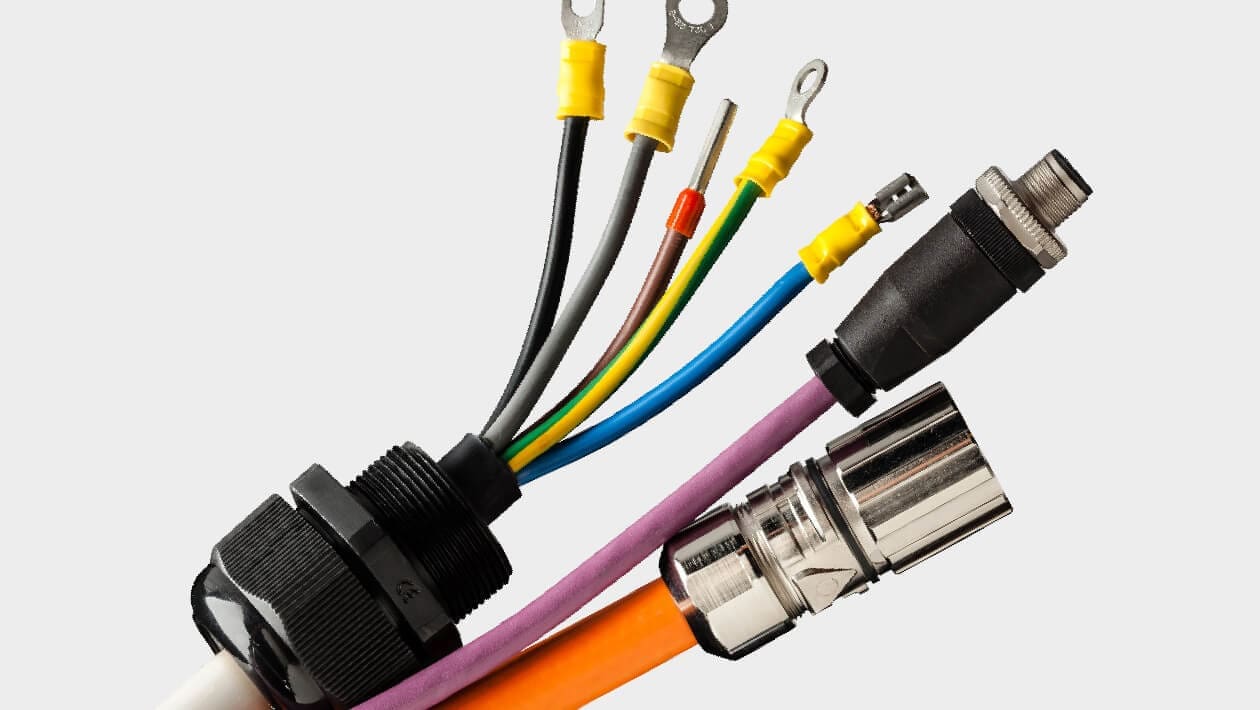
Testing the Finished Harness
The economics are stark: finding and fixing a fault on the test bench costs approximately 50 in labor and time, while that same fault discovered in a finished vehicle or aircraft can trigger a recall, costing upward of 5,000 per unit for diagnosis and repair. Modern testing is performed on automated systems like those from CableEye or Cirris that can test a complex harness with 500+ circuits in under 90 seconds, checking for continuity, insulation resistance, and sometimes even basic functionality.
The tester sends a low-current signal down each circuit and measures resistance, passing the circuit if it reads below a 2.0-ohm threshold. This catches missing wires or incorrect pinning. Next is an insulation resistance test (or shorts test), often called a hipot (high potential) test. This applies a high voltage—e.g., 1500 VAC for 60 seconds—between adjacent circuits and from each circuit to ground. The system measures the resulting leakage current; a reading below 5 mA confirms the insulation can adequately isolate the circuits. For data cables, additional tests like propagation delay (measured in nanoseconds) and impedance (e.g., 100 Ω ±5% for Ethernet) are critical.
| Test Type | Purpose | Key Parameters & Pass/Fail Criteria |
|---|---|---|
| Continuity (Opens Test) | Verify all intended connections exist. | Applied current: 10 mA. Max resistance: 2.0 Ω. |
| Insulation Resistance (Shorts/Hipot) | Verify no unwanted connections exist. | Applied voltage: 1500 VAC. Max leakage current: 5 mA. Test duration: 60 sec. |
| Dielectric Withstanding Voltage (DWV) | Stress-test insulation at extreme voltages. | Applied voltage: 2500 VAC. Max leakage current: 2 mA. Test duration: 60 sec. |
| Resistance/Impedance | Measure quality of a circuit or shield. | Max resistance for a 5-meter power wire: 0.05 Ω. Shield impedance: < 50 mΩ. |
A sample unit from the production run might be placed in a thermal cycling chamber where it is subjected to 100 cycles between -40°C and 125°C to ensure materials don't crack or contract excessively. Another might be mounted on a vibration table that simulates 5 years of road fatigue in just 24 hours at frequencies from 10 Hz to 500 Hz.
- Automated Optical Inspection (AOI): A vision system scans connector faces to verify 100% pin occupancy and that no pins are bent or missing. It can check that a seal plug is present in cavity #12 of a connector.
- Pull Force Test: A randomized sample of crimped terminals is subjected to a tensile pull test. A 16 AWG terminal must withstand at least 150 Newtons of force without being extracted from the wire.
- Functionality Check: For smart harnesses with resistors or diodes, the tester verifies component values. It checks a termination resistor measures 120 Ω ±1% and that a diode allows current flow in only one direction.
Crafting a cable harness involves precision across five core stages. Designers use 3D CAD models to map routes, accounting for 20+ variables like voltage. Wires are cut to ±0.1mm specs with automated strippers, stripping 1-2mm insulation. Assemblers secure connections on custom jigs, then bundle with 15-20 nylon ties. Final testing checks continuity at <0.01Ω resistance, ensuring 99.8% reliability.
