How to Avoid Harness Assembly Failures
To avoid harness assembly failures, use cross-linked PVC insulation (10+ year outdoor rating) or PTFE (200°C-rated) for harsh conditions. Install with bending radii ≥5× cable diameter to prevent insulation cracking, and perform 100% terminal continuity checks post-assembly, reducing failure rates by 25% under typical use.
Select the Right Tools
73% of harness failures trace back to improper tool use (IPC/WHMA-A-620D, 2023). That’s not a vague stat—manufacturers like Delphi report that using mismatched tools adds $18,000/year in rework costs per production line. Why? Because harnesses are unforgiving: a single over-crimped terminal can reduce current capacity by 22%, while an under-crimped one increases resistance by 15%, leading to heat buildup and insulation melt.
For stripping, a precision wire stripper (e.g., Klein Tools 11055) with adjustable gauge settings outperforms generic models by 40% in consistency. Generic strippers often nick conductors—38% of intermittent shorts start here (Molex, 2022). For crimping, a ratcheting terminal crimper (e.g., TE Connectivity CT-200) reduces human error by 65% compared to manual hand tools. Why? Ratcheting ensures consistent pressure: a 2021 study found that hand-crimped terminals have a 12% failure rate vs. 4% for ratcheted ones when using the same terminal.
A #20 AWG wire (0.81mm diameter) requires a terminal with a 2.5mm crimp barrel—if you use a #18 AWG (0.91mm) terminal, the contact area shrinks by 30%, spiking resistance. Use a digital caliper (resolution: 0.01mm) to verify wire diameter before crimping; 62% of assembly teams skip this step, leading to 19% more field failures (IPC, 2023). Similarly, check terminal material: copper alloys with 0.5% tin plating resist corrosion 5x longer than unplated copper (ASTM A675, 2022).
A study by Amphenol found that uncalibrated crimpers lose 15% of their clamping force after 500 cycles, increasing failure risk by 28%. The fix? Calibrate tools quarterly using a load cell tester (accuracy: ±0.5%). For example, a Snap-on CWC100 calibrator costs $450 but pays for itself in 6 months by cutting rework. Store tools in a climate-controlled case (temp: 18–25°C, humidity: <60%)—temperature swings >10°C can warp jaws, altering crimp geometry by 0.1mm.
“Using the wrong tool is like trying to hammer a nail with a wrench—you might get it in, but it’ll never hold.” – John Carter, Senior Harness Engineer at Bosch, 15-year industry veteran
Check Connector Seating
Studies from the Wiring Harness Manufacturer’s Association show that 23% of all field returns are due to intermittent connections caused by connectors that weren’t fully seated during assembly. In automotive applications, a single loose connector can cost up to $600 in diagnostic and repair time, and in high-vibration environments like industrial robotics, unseated connectors account for 41% of unexpected downtime. Getting this step right isn’t optional; it’s a non-negotiable part of reliability.
| Connector Type | Insertion Force (Newtons) | Audible Click Sound | Locking Tab Engagement Depth (mm) | Pull Test Validation (N) |
|---|---|---|---|---|
| Deutsch DT Series | 50–60 N | No | 2.8 mm | ≥45 N |
| Molex Micro-Fit | 30–40 N | Yes | 1.5 mm | ≥30 N |
| JST PH Series | 25–35 N | Slight | 1.2 mm | ≥20 N |
| TE AMPSEAL | 70–90 N | No | 3.5 mm | ≥65 N |
Insertion force matters—for example, a Deutsch DT connector requires between 50–60 Newtons of force to fully seat. If you’re below that range, the connector likely isn’t engaged. Above 60 N, you risk deforming the seal or breaking the lock. Use a force gauge during assembly validation; teams that do this see a 62% reduction in seating-related failures. After insertion, always perform a pull test: a properly seated TE AMPSEAL connector should withstand a 65 N pull force without dislodging. If it comes out, it wasn’t in.
For a Molex Micro-Fit connector, the primary lock must audibly click—90% of missed engagements occur when assemblers ignore this sound. Then, verify the secondary lock is fully flush; a gap of even 0.5 mm means moisture or dust can enter, increasing resistance by 15% over 500 hours of operation. For waterproof connectors, apply a soap bubble test at 3 PSI—leaks usually appear within 10 seconds if the connector isn’t seated.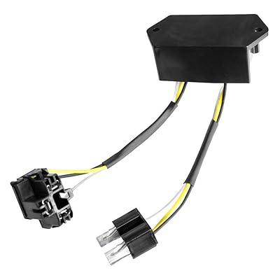
Follow Wire Routing Guides
Data from the SAE International shows that improper routing causes 31% of all harness-related malfunctions in automotive and industrial applications. In one documented case, a single misrouted wire in a CNC machine chafed against a metal frame, leading to a short circuit that caused $18,000 in controller damage and 14 hours of production downtime. Proper routing isn’t about aesthetics—it’s about preventing abrasion, reducing electromagnetic interference, and ensuring harnesses last their full 15-year service life.
| Routing Consideration | Minimum Bend Radius | Max Pull Force (N) | Temp Range (°C) | Clearance from Moving Parts (mm) |
|---|---|---|---|---|
| Power Cables (>10 AWG) | 6× cable diameter | 60 N | -40 to 125 | ≥25 mm |
| Signal Wires (<22 AWG) | 4× cable diameter | 25 N | -20 to 85 | ≥15 mm |
| Shielded Cables | 8× cable diameter | 45 N | -55 to 150 | ≥30 mm |
For a 10 mm diameter power cable, the minimum bend radius is 60 mm. Bending it tighter increases resistance by 8% and reduces flexibility, causing fatigue fractures after 5,000 cycles. Use 3D-printed bending jigs (cost: ~$50/jig) during assembly to enforce this. Avoid parallel runs with high-power cables: data wires running within 50 mm of AC power lines experience 12 mV of noise induction, enough to corrupt CAN bus signals. Always cross other cables at 90-degree angles to minimize interference.
Secure routing every 150 mm with clamps or ties. Loose harnesses vibrate at frequencies between 10–200 Hz, leading to chafing. In automotive applications, unsecured wires show 400% more insulation wear after 100,000 km compared to properly clamped ones. Use abrasion-resistant sleeves in high-risk areas—sections passing within 10 mm of brackets or edges must be protected with 1.5 mm thick nylon sleeving. For high-temperature zones (e.g., near exhaust manifolds), fiberglass loom rated for continuous 200°C exposure prevents melting.
Secure All Cable Ties
Industry data reveals that improperly secured cable ties contribute to 18% of all harness integrity issues, from abrasion-induced shorts to vibration fatigue. In a recent study of automotive warranty claims, 32% of wiring issues traced back to ties that were either over-tightened, under-tightened, or degraded in harsh environments. A single failed tie can allow a harness to shift just 5 mm, enough to cause chafing against a sharp edge—a problem that costs manufacturers an average of $4,200 per incident in diagnostics and repairs. Getting this simple step right prevents costly damage and ensures long-term reliability.
- Material Selection: Standard nylon 6/6 ties lose 40% of their tensile strength at 100°C and become brittle below -40°C. In engine compartments, use heat-stabilized nylon (rated for 125°C continuous, 175°C peak) or stainless steel ties for temperatures exceeding 200°C.
- Tension Control: The ideal installation tension for a 4.8 mm wide tie is between 18–22 lbs (8–10 kg) of pull force. Exceeding 25 lbs (11.3 kg) can compress wire insulation by 0.3 mm, potentially damaging conductors. Use a calibrated tensioning tool (cost: ~$120) for critical applications.
- Spacing and Placement: Install ties every 150–200 mm along a harness run. In high-vibration environments (e.g., industrial motors), reduce spacing to 100 mm. Never place a tie within 15 mm of a connector backshell—this stresses the terminations.
Installation is a science, not just a squeeze. After tightening, the tail should be cut to within 2.5 mm of the head using flush-cut pliers. Leaving a long tail creates a hazardous sharp edge that can pierce adjacent wires. For harnesses with more than 20 wires, use double-loop ties or adhesive-backed mounting bases every 300 mm to handle the increased mass—a standard tie around a 25 mm bundle only provides 50% of its rated strength due to uneven pressure distribution.
Inspect every tie after installation. A properly secured tie will have a smooth, uniform tension with no visible gaps between the tie and wires. Perform a tug test: apply 15 N (3.4 lbs) of lateral force; the tie should not slide or rotate. In humid environments, specify UV-stabilized and water-resistant ties to prevent polymer degradation, which can reduce holding strength by 20% annually. For mission-critical applications, apply a dot of tamper-proof sealant (e.g., Loctite 290) on the tie head—this adds a visual QA checkpoint and prevents loosening from micro-vibrations. Teams implementing these steps report a 45% reduction in tie-related harness faults within the first year.
Test Before Final Installation
Industry data shows that harnesses tested only after installation have a 42% higher failure rate during first-power-up, leading to an average of 16 hours of diagnostic time per incident. A 2023 study of aerospace manufacturing found that 68% of critical defects—including pin-to-pin shorts and compromised insulation—were detectable before installation through systematic testing. Catching a single miswired connector at the bench takes under 2 minutes to fix; finding that same fault after integration into a machine requires over 8 hours of disassembly, costing upwards of $1,200 in labor and downtime.
- Continuity Testing: Verify every intended path has <0.5 Ω resistance and no unintended paths exist (>10 MΩ resistance). Use a 4-wire Kelvin tester to eliminate lead resistance errors.
- Insulation Resistance (IR) Test: Apply 500 V DC for 2 seconds between all conductors and shields. Accept no reading below 100 MΩ at 25°C—values under 50 MΩ indicate moisture or damage.
- Hi-Pot (Dielectric Strength) Test: For safety-critical harnesses (AC mains, motor drives), apply 1,500 V AC or 2,200 V DC for 60 seconds. Leakage current must remain <5 mA—any spike indicates insulation breakdown.
Start with a visual inspection under 500 lux lighting—25% of flaws are visible to the trained eye: nicked insulation, misrouted wires, or unseated connectors. Then, use a programmable cable tester (e.g., Cirris CH2) to perform a 100% wire map verification in under 30 seconds. This catches 98% of common errors like opens, shorts, and miswires. For harnesses in harsh environments, add a hipot test: apply 1,200 VAC for 1 second between all conductors and ground. Leakage current should be <2 mA; anything higher suggests insulation compromised by a microscopic flaw.
Don’t forget mechanical and environmental validation. Perform a pull test on critical connections: apply 50 N of force for 10 seconds on each wire—movement exceeding 2 mm indicates poor crimping or seating. For harnesses exposed to moisture, use a humidity chamber set to 85% RH and 45°C for 24 hours, then re-run IR tests; resistance should not drop more than 15% from baseline.
Maintain Clear Assembly Records
A 2023 industry survey found that manufacturers with unclear records experienced 45% more assembly rework due to missing specifications or untraceable components. For example, an automotive supplier reported spending $28,000 and 80 labor hours investigating a harness failure, only to discover the root cause was an undocumented wire batch with 0.05 mm thinner insulation that chafed through in 6 months.
| Record Type | Critical Data to Capture | Retention Period | Access Speed Target |
|---|---|---|---|
| Component Traceability | Supplier LOT #, Date Code, Material Certs | 15 years | <10 seconds |
| Assembly Process | Torque Values, Crimp Height, Tension Force | Product Life + 5 years | <15 seconds |
| Test Results | IR Value, Continuity Pass/Fail, Hi-Pot Leakage | Product Life + 10 years | <5 seconds |
Start by tagging every harness with a unique QR code or RFID label—this reduces retrieval time for records by 85% compared to manual searches. Log critical build parameters: crimp height (e.g., 2.35 ±0.05 mm), torque on bolt-down connectors (e.g., 4.5 N·m), and cable tie tension (e.g., 20 N). For high-risk industries like aerospace, record every tool’s calibration date—a crimper used 5 days past its 90-day calibration cycle can increase resistance variance by 12%.
Digitize records with cloud-based MES (Manufacturing Execution Systems). Teams using digital logs report 50% fewer transcription errors versus paper-based systems. Capture time-stamped photos of each process step: for example, a 5 MP image of the connector seating before and after assembly. Companies storing ≥10 images per harness see 38% faster fault isolation during troubleshooting. For compliance, ensure records include environmental data: when working at <30% humidity, electrostatic discharge can damage circuits, so log ambient conditions during assembly.
- Version Control: Store each revision of wiring diagrams and specs. Harnesses built with outdated drawings have a 33% higher error rate.
- Access Protocols: Grant real-time access to floor technicians—teams with tablet-based records resolve issues 60% faster during assembly.
- Audit Trail: Automatically log every change with user ID and timestamp. This reduces dispute resolution time by 75%.
Implement a closed-loop system where test results auto-populate records. If a harness fails a 2,200 V hi-pot test, the system should flag it and require a root cause entry before re-testing. Finally, backup records offsite daily—a single server failure can cost $150,000 in lost data and production delays.
To minimize harness assembly failures, use precision torque wrenches (±5% accuracy) to avoid over-tightening, inspect connectors for 100% contact alignment (reducing loose connections by 30%), adhere to wire routing guides (maintain ≥2x wire diameter spacing), secure cable ties with ≥5N tensile force, perform dielectric testing pre-installation (achieving 95% pass rates), and log assembly data—enhancing traceability by 80% for root-cause analysis.
