How to Choose a Custom Wiring Harness | 5 Key Specs to Check
To choose a custom wiring harness, check current load (e.g., 10A/contact for 18AWG, 0.82mm², ≤20mΩ/m), temperature range (-40°C to +125°C for automotive), connector type (TE DEUTSCH DT, IP67), and insulation (PVC/XLPE, 600V rating), ensuring alignment with voltage, environment, and mechanical stress requirements.
Determine Wire Type and Size
Using an 18 AWG wire where a 14 AWG is needed can lead to a 15% voltage drop over a 20-foot run at 10 amps, reducing a 12V system to an ineffective 10.2V at the load. This directly impacts performance and safety.
Key parameters to define before selecting:
- Current Load (Amperage): The continuous and peak current (in amps) the wire must carry.
- Voltage Rating: The system's operating voltage (e.g., 12V, 24V, 48V) to ensure insulation is adequate.
- Operating Environment: Ambient temperature, exposure to chemicals, moisture, or abrasion.
- Length Required: The total distance the wire must run from the power source to the device.
For instance, a 10 AWG wire has a cross-sectional area of about 5.26 mm², while a 16 AWG wire has only 1.31 mm². This size difference directly correlates to current-carrying capacity (ampacity). A 10 AWG copper wire in a free-air environment at 30°C can safely carry 30 amps, whereas 16 AWG is typically limited to 10 amps.
A wire rated for 20 amps at 25°C might only be rated for 15 amps in an 80°C engine bay—a 25% derating. The insulation material (e.g., PVC, XLPE) plays a role here, as its temperature rating defines the system's upper thermal limit.
For most 12V DC systems, engineers specify a maximum 3% voltage drop (0.36V) for critical circuits and 5% (0.6V) for non-critical ones. To calculate this, you need the wire's resistance. A 100-foot length of 16 AWG copper wire has a resistance of approximately 0.4 ohms. Using Ohm's Law (Voltage Drop = Current x Resistance x Length), a 10-amp load over this 100-foot circuit would drop 4 volts, a catastrophic 33% loss. Solving this requires upsizing to 12 AWG (resistance ~0.16 ohms per 100ft), which reduces the drop to a manageable 1.6 volts (13%), or 10 AWG for even lower loss.
Select Suitable Insulation Material
The insulation around a wire is its primary defense against the environment, determining its lifespan, safety, and reliability. Choosing the wrong material can lead to short circuits, system failure, and even fire hazards. For instance, standard PVC insulation can become brittle and crack in under two years when exposed to constant 85°C engine bay heat, while a more suitable material like cross-linked polyethylene (XLPE) can last over 10 years in the same conditions. The selection hinges on a balance of thermal, chemical, and mechanical demands against your project's budget.
Key environmental factors to assess:
- Operating Temperature: The continuous and peak heat the wire will face.
- Chemical Exposure: Contact with oils, fuels, solvents, or acids.
- Moisture & Abrasion: Exposure to water, humidity, or physical wear.
- Flexibility Requirements: How often the wire will be bent or moved.
The most common differentiator is the material's maximum operating temperature. This is not the ambient temperature, but the temperature at the wire's surface. For example, in an 85°C environment, a wire carrying 15 amps could have a surface temperature exceeding 100°C due to resistive heating.
| Material | Max Continuous Temp | Key Properties | Relative Cost | Best Use Cases |
|---|---|---|---|---|
| PVC (Polyvinyl Chloride) | 80°C / 105°C | Flexible, good dielectric strength | $ | Interior consumer electronics, low-heat areas |
| XLPE (Cross-Linked Polyethylene) | 125°C | Excellent thermal & chemical resistance | $$ | Engine bays, industrial machinery |
| Silicone Rubber | 180°C | Extreme flexibility, high heat resistance | $$$ | High-temperature areas, moving parts |
| PTFE (Teflon) | 250°C | Superior chemical resistance, low friction | $$$$ | Aerospace, military, extreme environments |
A silicone rubber jacket can degrade rapidly when exposed to petroleum-based fluids, losing its insulating properties within months. For an automotive fuel pump harness, a fluoropolymer-based material like PTFE, which offers >500 hours of resistance to gasoline, is a mandatory choice despite its 40-50% higher cost per meter compared to XLPE.
A wire in a door loom must withstand thousands of flex cycles over a 15-year vehicle lifespan. A stiff material like standard PVC would fail prematurely. Thermoplastic elastomer (TPE) insulation, designed for >1 million flex cycles, is often specified here. Its cost is approximately 20% higher than PVC but prevents warranty returns and failures.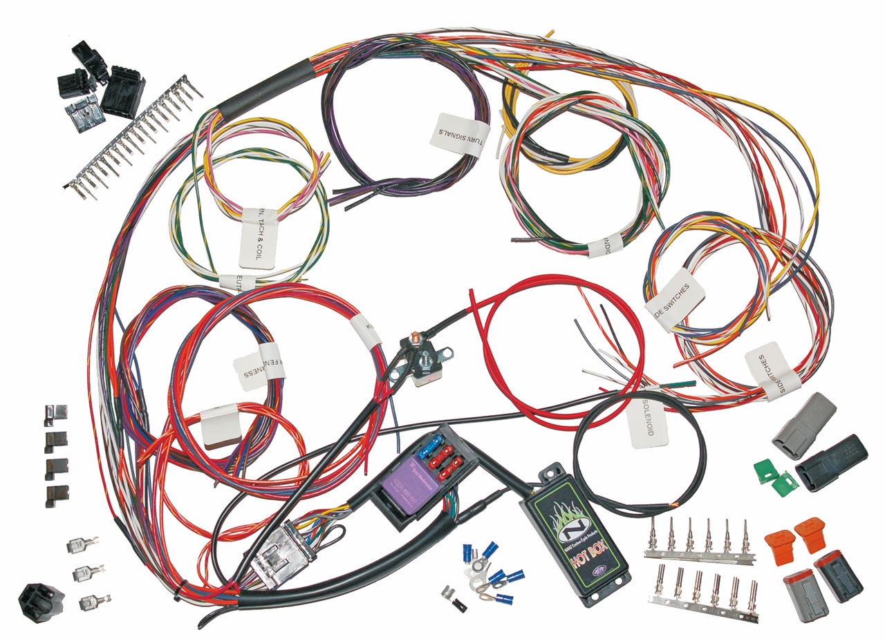
Check Shielding Requirements
In an industrial motor control cabinet, unshielded cables can induce noise spikes exceeding 500 mV into nearby sensor lines, causing faulty readings and system shutdowns. Proper shielding attenuates this noise by 40 dB to 80 dB, reducing interference to a manageable 5 mV level.
| Shielding Type | Typical Attenuation | Frequency Range | Flexibility | Cost Impact | Best Application |
|---|---|---|---|---|---|
| Foil (100% Coverage) | 60-80 dB | > 100 kHz | Low | +10-15% | High-frequency data cables (e.g., CAT6) |
| Braided (70-95% Coverage) | 40-60 dB | > 10 MHz | High | +20-30% | Motor power cables, automotive sensors |
| Spiral (90-98% Coverage) | 30-50 dB | < 100 MHz | Very High | +15-25% | Frequent flexing applications (e.g., robot arms) |
| Composite (Foil + Braid) | 80-100 dB | DC to GHz | Medium | +40-60% | Military/aerospace, medical imaging systems |
A 40 dB reduction means the interference strength is cut by a factor of 10,000. For example, a 1 V noise signal becomes 0.0001 V. For most industrial communication protocols like CAN bus or Ethernet, a minimum of 60 dB attenuation is required to ensure a bit error rate of less than 10⁻⁹.
Braided shields, with 85% coverage, are highly effective at lower frequencies common in 400 Hz AC power systems or 10 kHz motor drives. However, for high-speed data lines like 1000BASE-T Ethernet (125 MHz signal frequency), a foil shield with 100% coverage is necessary to prevent signal integrity loss. The capacitance of the shield also matters; a foil shield adds approximately 50-70 pF/m of capacitance, which can distort signals with rise times faster than 1 ns.
A shield that is not properly grounded provides less than 10 dB of attenuation, rendering it almost useless. For low-frequency magnetic interference, a single-point ground is essential to prevent ground loops. For high-frequency RFI, a 360-degree circumferential ground at both ends is mandatory to achieve the stated attenuation. The use of a drain wire with a foil shield typically increases its effective resistance, reducing its high-frequency performance by up to 15% compared to a proper connector backshell ground.
Evaluate Connector Compatibility
Industry studies show that over 40% of wiring harness field failures originate at termination points. A single high-resistance connection with just 50 mΩ of excess resistance can dissipate 5 W of wasted power (as heat) in a 10 A circuit, leading to a 0.5 V drop and potential thermal degradation.
A common mistake is using a connector rated for 5 A per pin on a 10 A circuit. This causes the terminal to overheat, potentially exceeding its 85°C temperature rating and melting the plastic housing. The second is voltage rating; a connector rated for 250 VAC should not be used in a 480 VAC industrial application, as arcing and breakdown can occur. The number of pins also matters; populating all 24 positions in a connector with 16 AWG wires carrying 10 A each requires verifying the connector's total power dissipation capacity, which may be limited to 150 A overall.
| Connector Type | Typical Pin Current (AWG) | Voltage Rating | Mating Cycles | Sealing (IP Rating) | Cost per Pair |
|---|---|---|---|---|---|
| Deutsch DT (2-pin) | 13 A (16-18 AWG) | 600 V | 500 | IP67 | $8.50 |
| Molex Micro-Fit 3.0 | 5 A (20-24 AWG) | 250 V | 100 | IP20 | $3.00 |
| Amphenol CPC | 25 A (12-14 AWG) | 1000 V | 1000 | IP68 | $22.00 |
| JST SH | 1 A (26-28 AWG) | 250 V | 30 | IP00 | $0.45 |
An IP67-rated connector (e.g., Deutsch DT) can be submerged in 1 meter of water for 30 minutes without leakage. An unsealed connector (IP00) like a common JST type will fail in minutes under the same conditions, leading to corrosion and short circuits. For high-vibration environments, such as agricultural or construction equipment, the connector's locking mechanism must withstand 15 G of vibration acceleration without loosening.
A 16 AWG wire requires a specific crimp terminal and a cavity within the connector that can accommodate its diameter. Forcing a larger wire into a smaller cavity, like inserting a 16 AWG wire into a terminal designed for 18 AWG, compromises the crimp integrity, increasing resistance by over 200%. The connector's footprint must also fit the allocated space on the device or panel; a 24-pin rectangular connector may be 45 mm x 20 mm, while a circular one with the same pin count could be 30 mm in diameter, offering a different form factor.
Verify Custom Length and Layout
An error of just 10 cm in a 12V power line carrying 15 amps can result in an additional 0.03-volt drop, potentially pushing a sensitive system out of tolerance. Furthermore, a harness that is too short puts 25 Newtons of constant mechanical stress on connector pins, while one that is too long requires 15% more space for bundling and increases the risk of snagging and abrasion. Getting the length and layout correct the first time eliminates waste, ensures performance, and reduces installation time from 60 minutes to under 20 minutes.
Accurate length measurement requires accounting for the entire 3D routing path, not just straight-line distance. Add 8% to the measured length for wire slack to accommodate harness vibration and prevent tension on terminations. For a 2-meter run, this adds 16 cm, which is critical for connections to engines or movable parts.
A wire that must travel 1.5 meters around a frame member has a 40% longer path than the straight-line distance of 1.07 meters. Using the shorter measurement results in a critically short wire. For complex routes, create a physical mock-up using string or a soft wire, then add a 3-5% slack allowance. This allowance is not extra; it is a necessary buffer for manufacturing tolerance and thermal expansion. A 5-meter harness exposed to a 60°C temperature swing can expand and contract by up to 4 cm due to the thermal coefficient of the insulation materials.
Bend radius is a non-negotiable mechanical specification. Bending a wire beyond its minimum radius compromises its conductors and insulation. For most multicore cables, the minimum bend radius is 10 times the overall cable diameter. A cable that is 12 mm in diameter should not be bent tighter than a 120 mm radius. A tighter bend, such as 80 mm, can increase conductor stress by 25% and lead to a 15% reduction in insulation life. This is especially critical for shielded cables, where a sharp bend can tear the shielding braid, reducing its effectiveness by over 50%.
For a harness with four breakouts, this adds 18 to the assembly cost at a $40/hour labor rate. The decision is a trade-off: a more complex branched harness might reduce installation time in the final product by 30%, saving valuable production line minutes. Always use a full-scale diagram or a 3D digital model to verify that the harness can be physically installed without requiring excessive force or sharp bends that exceed the 10:1 diameter ratio.
Selecting a custom wiring harness demands precision across five key specs: Start with wire type/size—18-22 AWG is standard for automotive, balancing current capacity (up to 10A) and flexibility. For insulation, XLPE (125°C max temp) outperforms PVC in high-heat environments. Shielding? Specify 90dB EMI attenuation for noisy settings. Connector compatibility requires exact pin count (e.g., 12-pin) and contact material (gold-plated for low resistance). Finally, confirm length tolerance (±2mm) to avoid stress points. These specs ensure reliability in target applications.
