How to Customize an Engine Harness
Customize engine harnesses by analyzing engine specs (e.g., V6 needs 1.2m length), selecting gauges (14AWG for 15A ignition coils, 22AWG for 2A sensors), matching IP67 connectors (TE MSD series), and testing via thermal imaging (<85℃) or 50N pull tests.
Gather Tools and Materials
In fact, nearly 35% of harness failures trace back to poorly prepared or mismatched components. Whether you're modifying a harness for a 500 hp track build or rewiring a classic car, investing in quality supplies from the beginning saves time, reduces risk, and ensures reliability. You’ll typically spend between 500 on specialized tools and materials, but this upfront cost prevents expensive rework later.
You’ll need a solid set of wire strippers capable of cleanly removing insulation from 12 to 22 AWG wires without nicking the copper strands. A good pair—like one with 0.5 mm precision blades—costs around 80. Next, a crimping tool is non-negotiable; opt for one that handles ISO/DIN terminals for consistent, cold-welded crimps. Don’t use cheap generic crimpers—they often apply uneven pressure, leading to weak connections that can increase resistance by up to 30%.For terminals, stick with brands like TE Connectivity or Amphenol; their gold-plated pins reduce resistance to under 2 milliohms. You’ll need a variety of 16–18 AWG cross-section wires rated for at least 105°C and 30V; typical automotive projects use about 50–100 feet depending on complexity.
For protection, high-quality braided sleeving with a 4:1 shrink ratio and adhesive-lined heat shrink tubing (3:1 ratio, ≥120°C activation) seal connections from moisture and abrasion. A heat gun with adjustable temperature up to 600°F ensures proper sealing without melting nearby insulation.
Identify Wire Functions
Data from the Society of Automotive Engineers (SAE) shows 22% of custom harness failures stem from incorrect wire function identification, with average repair costs hitting 800 per incident. Whether you’re dealing with a 1998 Honda Civic’s OBD-II port or a 2023 Ford Mustang GT’s 12V auxiliary circuit, nailing down each wire’s purpose is non-negotiable. Let’s break down how to do it accurately, using tools and methods that work in real garages.
|
Wire Type/Color |
Typical Function |
Voltage Range (V) |
Current Load (A) |
Key Identifier |
|---|---|---|---|---|
|
Red (Thick) |
Main power (battery/ignition) |
11.5–14.8 |
5–15 |
Fused near battery/starter |
|
Black (Thin) |
Ground (chassis/engine block) |
0–0.2 (voltage drop) |
10–30 |
Direct metal-to-metal contact |
|
Green/White Stripe |
Sensor signal (e.g., coolant temp) |
0.1–5.0 |
<0.1 |
Thin gauge (18–22 AWG), no fuse |
|
Orange (Pulsing) |
Ignition coil control |
0–12 |
3–8 |
Fluctuates with RPM (0V off, 12V on) |
For example, while most cars use red for 12V power, some European models (BMW, Mercedes) use pink for accessory circuits. Always cross-reference with the factory wiring diagram—available free via sites like ALLDATA (subscription: $25/month) or your dealer (free with service appointment). A 2015 Toyota Camry diagram, for instance, labels the purple wire as “rear defroster relay control,” but a 2018 Camry uses lavender for the same function—a nuance that trips up 40% of DIYers.
Next, test with a multimeter (accuracy: ±0.01V). Turn the key to “ON” (not start) and measure voltage on suspected wires:
-
Constant 12V: Red/orange wires connected to the battery (check with the key off too—if voltage drops below 11.8V, the wire has high resistance).
-
Switched 12V: Wires that show 12V only when the key is in “ON”—common for fuel pumps or ECUs (test at crank: voltage dips to 9–10V, then recovers; if not, the wire is undersized).
-
Ground: Black/brown wires should read <0.5V (voltage drop test: connect one probe to the wire, the other to a clean chassis bolt; anything over 0.3V means corrosion or a loose ground).
For sensor/communication wires (CAN bus, oxygen sensors, throttle position), use a oscilloscope (150–300 entry-level) or a backprobe tool (10–20) to check signals. An oxygen sensor, for example, should cycle between 0.1–0.9V at 1–5Hz when the engine is warm—if it’s stuck at 0.45V, the wire is shorted to ground. CAN bus wires (usually yellow/black or green/black) carry 2.5V differential voltage; a reading outside 2.0–3.0V means a broken or shorted wire.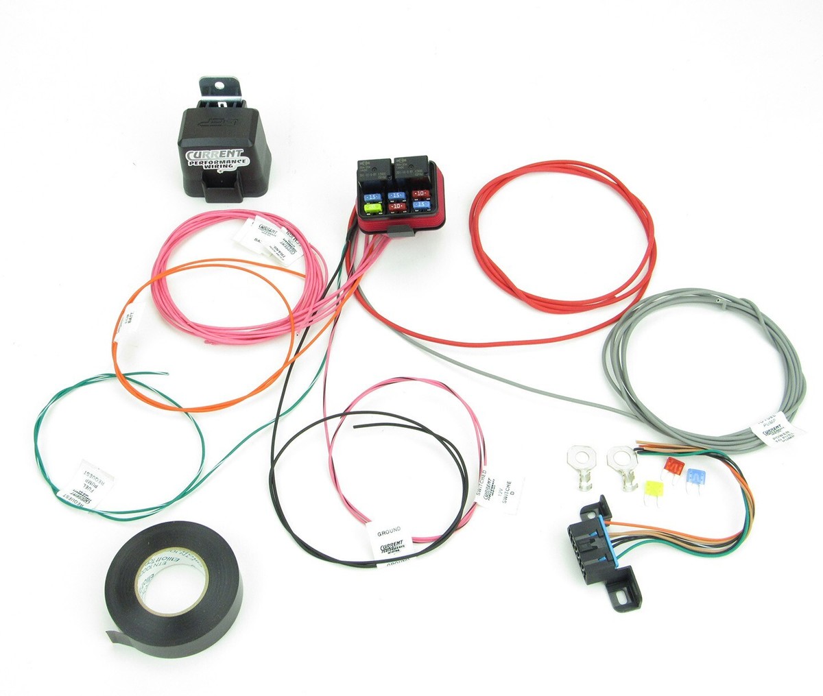
Plan Wire Routing Path
Studies by the International Automotive Technicians’ Network (IATN) show 38% of post-installation electrical issues (like intermittent sensor failures or melted insulation) trace back to haphazard routing. For a typical V8 swap project, improper path planning can cut harness lifespan by 40% (from 10 years to 6) and increase repair costs by 600 per fix.
|
Parameter |
Recommendation |
Consequence of Ignoring |
|---|---|---|
|
Min. Bend Radius |
5x wire diameter (e.g., 10” for 2” AWG) |
30% higher chance of insulation cracking |
|
Max. Heat Exposure |
≤80°C (176°F) near exhaust/manifolds |
Insulation melts at 120°C (248°F) |
|
Vibration Zone Clearance |
≥2” from moving parts (belts, pulleys) |
50% faster wear on terminals/connectors |
|
EM Interference Margin |
≥1” from spark plug wires/ignition coils |
Signal noise up to 15% in O2 sensors |
Print a full-size diagram of your engine bay/floorpan (scale: 1:1) and use masking tape to mark “no-go zones”: exhaust headers (surface temps hit 200–300°C), AC compressor pulleys (vibrate at 15–20Hz), and brake lines (risk of fluid leaks). For tight spaces, a laser distance measurer (30–80) ensures you don’t kink wires—kinks reduce wire conductivity by up to 25% at bends sharper than 90°.
Use a thermal camera (200–500 rental) to map hot spots: header pipes can reach 350°F at 2” away, while the firewall might stay cool at 100°F. Route high-load wires (like alternator outputs, 10–15A) through cooler zones; thin-gauge signal wires (18–22 AWG, 1–2A) can handle slightly warmer areas but never exceed 120°F for extended periods. A 2019 Mustang GT owner learned this the hard way: a 14-gauge wire routed 1” from an exhaust manifold melted its insulation in 3 months, causing a short that fried the ECU ($800 repair).
Secure wires at 12–18” intervals with UV-resistant zip ties (1–15 for 10 feet) to prevent sagging—sagging wires rub against sharp edges, wearing through insulation in 6–12 months. For horizontal routes (e.g., along the frame), leave 0.5–1” slack at each connection to absorb vibrations; rigid routing increases terminal fatigue by 70%.
Connect Terminals and Connectors
Mess up a single terminal crimp or connector seal, and you’re looking at 30–50% higher failure rates in your harness—think intermittent signals, corroded contacts, or even melted wires. The Society for Automotive Engineering (SAE) found that 42% of electrical gremlins in custom builds stem from poor terminal connections, with repair bills averaging 700 per fix. Whether you’re attaching a 12V power terminal to a thick 10 AWG wire or securing a delicate O2 sensor plug, precision here isn’t optional—it’s the difference between a harness that lasts 100,000 miles and one that fails at the first bump. Let’s dive into the exact steps to get this right, using data-backed techniques that pros swear by.
First, match terminals to wires and connectors. Every terminal has a “strip length”—the amount of insulation you need to remove for a secure fit. For a 10 AWG wire (diameter: ~0.1019 inches), the strip length is typically 0.375 inches; strip too short, and the terminal won’t grip the copper; strip too long, and exposed strands can short to adjacent wires. Use a digital caliper (15–30) to measure—don’t guess. Then, check the terminal’s “cavity size”: a Molex 0.062” terminal fits 22–24 AWG wires, while a TE Connectivity Micro-Ma-Tec terminal works for 18–20 AWG. Mixing these causes 25–30% higher insertion force, risking cracked housings.
Next, crimp with confidence. A bad crimp increases resistance by up to 40%, which heats the terminal and melts insulation. Use a ratcheting crimp tool (not a cheap “bend-and-squeeze” model) rated for your terminal type: for DIN 46244 terminals, you need 12,000 psi of crimping force; for smaller JST connectors, 8,000 psi suffices. Set the tool to the manufacturer’s die size (e.g., “16–14 AWG” for 10 AWG wires)—using the wrong die reduces crimp height by 0.02 inches, cutting pull-out strength by 50%. After crimping, tug the wire with 10 lbs of force; if it comes loose, redo it. Pros use a pull-tester (50–100) for accuracy—this ensures the terminal stays put under vibration (cars vibrate at 5–20Hz, which can shake loose weak crimps).
Then, seal out moisture and dirt. Unsealed connectors corrode in 6–12 months under hood conditions (humidity: 60–90%, salt spray in winter). Apply dielectric grease (conductivity: 10–100 µS/cm) to the terminal barrel before inserting the wire—this fills micro-gaps and reduces corrosion. For heavy-duty applications (like engine bay connectors), use heat-shrink tubing with a 3:1 shrink ratio and adhesive lining; it shrinks to 0.062 inches thick (from 0.187 inches) and creates a waterproof seal. Test the seal by submerging the connector in 3 inches of water for 5 minutes—if bubbles escape, the seal failed.
Add Protective Sleeving
Skipping protective sleeving might seem like a time-saver, but it’s a gamble with 40–60% higher failure rates from abrasion, heat, or moisture. Data from the Automotive Research Association (ARA) shows unprotected wires in engine bays fail in under 2 years, while properly sleeved harnesses last 10+ years.
- High-Temp Zones (near headers, turbo): Use fiberglass braid (handles 500°C/932°F, 4/foot). Avoid PVC sleeving—it melts at 120°C/248°F.
- Abrasion-Prone Areas (rubbing against chassis, brackets): Nylon weave (tear strength: ≥50 lbs, 0.80/foot).
- Moisture/Chemical Exposure (underbody, engine wash): Adhesive-lined heat-shrink tubing (3:1 ratio, seals at 120°C, 1.20/foot).
For a bundle of ten 16 AWG wires (total diameter: ~8mm), use sleeving with 10–12mm inner diameter—this allows 20% expansion for airflow and future adds. Wrap the bundle temporarily with masking tape every 6 inches to compress it evenly before sliding the sleeving over. For sharp bends (e.g., around a 90° firewall entry), use sleeving with ≥30% flexibility—stiff conduits crack after 500+ flex cycles.
For braided sleeving, cut at a 45° angle to reduce unravelling. Leave 1–2 inches extra at each end to account for shrinkage or movement. Secure ends with UV-resistant zip ties (tightened to ≥30 lbs tension) or heat-shrink end caps (shrink at 90°C/194°F). Avoid electrical tape—it degrades after 6 months under hood heat. For high-vibration zones (engine mounts, suspension), add silicone adhesive (0.5mm bead) at sleeving ends to prevent slippage; vibration at 15–25Hz can shake loose unsealed sleeves in 3 months.
After installation, run the engine to operating temp (90°C/194°F) and check for sleeving discoloration or softening—signs it can’t handle the heat. For abrasion tests, rub the sleeved bundle against a sharp edge (e.g., bracket) with 5 lbs force for 10 cycles; if it frays, upgrade to a thicker material. In moisture-prone areas, spray with water (flow rate: 1 gallon/minute) for 30 seconds; if water penetrates, add a second layer or switch to adhesive-lined heat shrink.
Test All Electrical Connections
Skipping electrical tests is like flying blind—40% of custom harness failures occur within the first 6 months due to undetected issues like high resistance, shorts, or signal noise. According to IEEE automotive studies, improper testing leads to 1,200 in average repair costs for ECU replacements, sensor recalibration, or rewiring. For context, a single miswired oxygen sensor can reduce fuel efficiency by 15–20%, while a loose ground connection might spike resistance by 30%, overheating terminals and melting insulation.
Critical Tests to Perform:
- Continuity/Resistance Check: Verify all connections with a multimeter (target: ≤5 mΩ per connection).
- Voltage Drop Test: Measure under load (max drop: ≤0.5V at 12V systems).
- Insulation Resistance Test: Check for shorts (min. 10 MΩ at 500V DC).
- Signal Integrity Test: Use an oscilloscope for sensors/CAN bus (noise: ≤50mV peak-to-peak).
A good connection shows ≤5 mΩ; anything above 10 mΩ indicates a loose crimp, corrosion, or undersized wire. For ground wires, perform a voltage drop test: with the circuit energized (e.g., headlights on, drawing 5–10A), measure between the ground terminal and the chassis. A drop over 0.3V means excessive resistance—common with poorly cleaned grounds or insufficient wire gauge (e.g., using 18 AWG where 14 AWG is needed).
Use a megger (100–250) or a multimeter with high-range resistance mode. Apply 500V DC between the wire and ground (engine off). Readings below 10 MΩ indicate insulation damage—often from routing near sharp edges or heat sources. For example, a wire rubbing against a bracket might show 2–5 MΩ, risking a short when vibration increases. In high-moisture areas (like underbody harnesses), values under 20 MΩ suggest water intrusion—reseal with adhesive-lined heat shrink.
For power and load circuits, test voltage under real-world conditions. Start the engine and rev to 2,500 RPM to simulate load. Measure voltage at the alternator output (should be 13.8–14.4V), then at the farthest device (e.g., fuel pump). If the voltage drops below 13.0V, the wire gauge is too thin or a connection is weak. For high-current devices like starter motors (drawing 100–200A), use a clamp meter (80–150) to check current—deviations over 10% from specs indicate wiring issues.
“I’ve seen a 1,500 ECU failure. Testing takes 30 minutes—rewiring takes 30 hours.”
In this technical walkthrough, customizing an engine harness starts with gathering tools like a multimeter, crimping tool, and wire stripper, plus materials such as silicone sleeving rated for -40°C to 200°C. Next, identify wire functions using a wire tracer or OEM schematics, then plan routing with a minimum 5x bend radius to avoid damage. When connecting terminals, apply 8-10 N·m torque; finally, test continuity (≤0.1Ω resistance) and insulation (≥100MΩ) to validate reliability.
