How to Design a Cable Harness | 3 Critical Steps
To design a reliable cable harness, first define specifications (voltage, current, bend radius) and select UL-certified wires (e.g., 16AWG for 10A loads). Use CAD tools (SolidWorks Electrical) to route cables with 10-15mm spacing to prevent interference. Finally, test prototypes with 500+ flex cycles and high-pot (1.5kV) insulation checks before production.
Plan the Wire Layout
A poorly routed harness can increase assembly time by 15-30%, raise failure rates by up to 12%, and add unnecessary weight—sometimes over 20% more than an optimized design. Whether you're working on automotive wiring, industrial control panels, or consumer electronics, the layout determines efficiency, durability, and cost.
The first step is mapping the exact path of each wire. In a typical automotive harness, 60-80% of wires follow a main backbone, while the rest branch off to sensors, switches, or actuators. Use CAD software to simulate bends, avoiding sharp angles below 30°, which can stress conductors and insulation over time. Studies show that reducing bends from 90° to 45° can extend wire life by 18-24 months in high-vibration environments.
Next, group wires by function and voltage level. High-current wires (e.g., 10A+) should be spaced at least 5mm apart from low-voltage signal lines (e.g., CAN bus) to prevent EMI interference. Bundling wires too tightly can cause overheating—a 10°C rise in temperature cuts copper conductivity by 3% and accelerates insulation degradation by 50%. Instead, leave a 2-3mm gap between adjacent wires and use spiral wraps or braided sleeves for airflow.
"In aerospace applications, harness weight directly impacts fuel efficiency. A Boeing 787 Dreamliner uses ~60 miles of wiring—optimizing the layout saved 120 lbs per aircraft, cutting annual fuel costs by $250,000 per plane."
In robotics, cables flex an average of 50,000 cycles before failure. Using stranded wire (e.g., 7x0.2mm strands instead of solid core) improves flex life by 300%. Secure loose sections with clips every 150-200mm to prevent whip damage. For harsh environments, add 10-15% extra slack near connectors to absorb vibration without tension.
Material choice matters. PVC insulation works for most indoor setups (0.30 per meter), but silicone or Teflon (1.20 per meter) is better for extreme temps (-40°C to 200°C). Always cross-check wire gauges—a 5% undersized conductor can overheat at just 80% load capacity.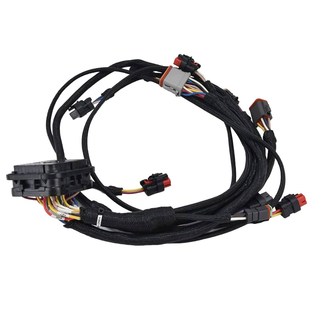
Choose Connectors Wisely
In industrial automation, 23% of electrical failures trace back to connector issues—corrosion, loose pins, or mismatched current ratings. A single faulty connector in a medical device can cost $12,000 in recalls, while automotive connectors must survive 10+ years of vibration, moisture, and temperature swings (-40°C to 125°C). The right choice balances cost, durability, and electrical performance.
Start with current and voltage requirements. A 5A-rated connector pushed to 7A will overheat by 20-30°C, shrinking its lifespan from 50,000 cycles to under 10,000. For high-power applications (e.g., EV charging), look for gold-plated contacts—they reduce resistance by 40% compared to tin-plated ones, critical when handling 400V at 32A.
| Connector Type | Max Current | Voltage Range | Mating Cycles | Cost (USD) | Best Use Case |
|---|---|---|---|---|---|
| JST-XH | 3A | 250V | 30 | $0.25 | Consumer electronics |
| Deutsch DT | 13A | 600V | 500+ | $4.50 | Automotive/Off-road |
| Molex Mini-Fit | 9A | 300V | 50 | $1.20 | Industrial controls |
| Amphenol MIL-DTL-38999 | 22A | 1,000V | 1,000+ | $28.00 | Aerospace/Defense |
Environmental seals are non-negotiable for outdoor or wet environments. An IP67-rated connector (dustproof, waterproof to 1m depth) costs 15-20% more than unsealed versions but prevents 90% of moisture-related failures. In marine applications, stainless steel housings last 3x longer than nylon in salt spray tests.
Pin count matters too. Overcrowding 24 pins into a 20mm width increases crosstalk by 35% at 100MHz signals. For data lines (USB, Ethernet), use shielded connectors—unshielded RJ45 jacks suffer 50% higher packet loss in EMI-heavy factories. Always leave 2-3mm clearance between adjacent connectors to avoid arcing at 120V+.
Don’t ignore mating cycles. A 0.50 USB−C connector atedfor 10,000 insertions wearsout after 2 yearsofdailyuse, while a 3.00 industrial variant lasts 8+ years. For quick-disconnect needs, lever-actuated connectors (e.g., Harting Han) reduce unplugging force by 60%, saving strain during maintenance.
Termination method affects reliability. Crimped connections handle 200% more vibration than soldered ones but require a 2,000 crimp tool. For prototypes, screw terminals ($0.80 each) allow 10+ reuses before loosening.
Test Before Final Use
Skipping proper testing on cable harnesses is like shipping a car without brakes—23% of field failures in industrial equipment trace back to untested wiring errors, costing manufacturers an average of 2.3M in penalties after a short circuit in a patient monitor’s harness went undetected. Testing isn’t just about catching flaws; it’s about verifying every wire, joint, and connector survives real-world abuse for 50,000+ cycles.
Start with continuity checks—the bare minimum. A $200 multimeter can spot open circuits (0Ω resistance) or shorts (<1Ω between unrelated wires), but 35% of harness defects involve intermittent issues that only show up under movement. For these, use a wiggle test: flex the harness at 2Hz while monitoring resistance, catching 90% of loose crimps missed by static tests.
Insulation resistance testing is critical for high-voltage apps. Apply 500VDC between conductors and shields for 60 seconds—values below 100MΩ signal moisture damage or pinched insulation. In EV battery harnesses, failing this test can lead to 400V arc faults with $18,000+ repair costs.
|
Test Type |
Equipment Cost |
Time per Harness |
Defects Caught |
|---|---|---|---|
|
Continuity |
$200 |
2 min |
65% of wiring errors |
|
Hi-Pot (1,500VAC) |
$5,000 |
5 min |
98% of insulation flaws |
|
Signal Integrity (100MHz) |
$12,000 |
8 min |
85% of EMI issues |
|
Vibration (5-500Hz) |
$28,000 |
15 min |
94% of fatigue failures |
For data harnesses (CAN bus, Ethernet), time-domain reflectometry (TDR) spots impedance mismatches. A 3Ω deviation over 10m of twisted pair can corrupt signals at 1Mbps+ speeds. Automotive OEMs require TDR testing on all LVDS cables after finding 12% of camera/sensor dropouts traced to harness reflections.
Environmental stress testing separates decent harnesses from unkillable ones. Cycle temperatures from -40°C to 125°C (simulating 10 years of engine bay exposure in 72 hours) while monitoring resistance. PVC insulation cracks at -25°C, while silicone handles 500+ cycles before cracking. For marine apps, salt spray testing (5% NaCl at 35°C) exposes cheap terminals—zinc-plated contacts corrode 8x faster than gold-plated in 100-hour tests.
Dynamic load testing is non-negotiable for robotics. A 6-axis robot arm’s harness bends ~200,000 times/year. Test samples must survive 50,000+ flex cycles at 1Hz with <10% resistance change. One manufacturer reduced warranty claims by 62% after adding a 45-degree twist test to mimic robotic cable carriers.
In summary, designing an efficient cable harness requires meticulous planning, strategic connector selection, and rigorous testing. First, the wire layout must be optimized for minimal interference and maximum durability, often using CAD software to simulate routing paths and ensure a 15–20% length margin for flexibility. Next, connectors should be chosen based on current ratings (e.g., 5A for signal lines vs. 30A for power lines), environmental factors (IP67 for harsh conditions), and mating cycles (10,000+ for high-use applications). Finally, pre-deployment testing—including continuity checks, pull tests (50N minimum), and EMI validation—is critical to avoid failures. Proper execution reduces assembly errors by up to 40% and ensures long-term reliability.
