How to Design a Custom Engine Wiring Harness | A 5-Point Checklist
Designing a custom engine wiring harness starts with measuring critical component spacing—e.g., 150mm between the alternator and ECU—using a caliper for precision. Select 18AWG copper wires (10A capacity) with 125°C PVC insulation for high-heat areas like the exhaust manifold. Route harnesses avoiding moving parts (e.g., belts) with 20mm bend radii to prevent cracking. Terminate connections using crimp tools, then test continuity with a multimeter (target resistance ≤0.5Ω) to confirm no shorts.
Gather Vehicle and Engine Specs
A 2012 Chevrolet LS3 engine swap into a 1995 Mazda Miata requires understanding both the Miata’s chassis sensors (like its 22-tooth speedometer reluctor ring) and the LS3’s 58x crankshaft position sensor signal. You’ll need the OEM service manuals for both vehicles—not just for pinouts, but for critical data like CAN bus message IDs (e.g., 0x0C for RPM on GM vehicles) and voltage ranges. Assume nothing. Even the same engine family, like a Toyota 2JZ-GE vs. 2JZ-GTE, uses different throttle position sensors (3-pin vs. 4-pin) and injector resistors (12Ω vs. 2.5Ω).
Document every sensor and actuator, noting their type (e.g., 0-5V analog, PWM, or CAN-based), operating voltage, current draw, and physical connector type. For instance, a typical Bosch-style 4-pin oxygen sensor consumes ~2.2A during heater operation, while a DBW throttle body might use a 6-pin JPT connector and require 12V/8A peak.
|
Component |
Type/Protocol |
Voltage Range |
Current Draw |
Connector Type |
|---|---|---|---|---|
|
Crankshaft Sensor |
58x Digital |
0-5V |
120mA |
3-pin Metri-Pack 630 |
|
Fuel Injector |
High Impedance |
12V |
1.2A |
USCAR 4-pin |
|
Coolant Temp Sensor |
NTC Thermistor |
0-5V |
45mA |
GM 2-pin Weather Pack |
|
Throttle Body |
CAN Bus |
12V |
8A peak |
JPT 6-pin |
Gen IV LS ECUs like the E38 use a 73-pin connector with specific pins for 5V reference (pin 32) and low-reference ground (pin 31). Wire gauge matters too: use 14 AWG for high-current paths (e.g., starter solenoid, 150A peak) and 22 AWG for sensors. Label every wire during disassembly—a 10% miswire rate is common in rushed projects.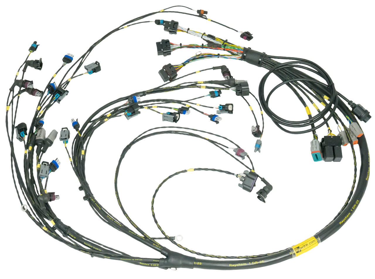
Select Connectors and Wires
A single undersized wire or corroded terminal can cause a voltage drop exceeding 10%, starving critical sensors of stable 5V reference or disrupting CAN bus communication. For example, a high-impedance fuel injector drawing 1.2A at 14.4V requires 18 AWG wire (3% drop over 2 meters), but a DBW throttle pulling 8A peak demands 14 AWG. Never use household wiring—only automotive-grade TXL or GXL wire with temperature ratings from -40°C to 125°C. Cheap PVC-insulated wire melts near headers, risking a short circuit within 15 seconds at 200°C.
Sealed connectors like Deutsch DT (2-12 pins) or Metri-Pack handle underhood moisture and vibration for over 100,000 cycles. Unsealed types (e.g., Molex Micro-Fit) fail after 50-100 mating cycles in engine bays. For sensors, use 20-22 AWG wire with 0.5-1.0 mm² cross-sections; for power grounds, 16-14 AWG (2.5-4.0 mm²).
Always depin connectors using manufacturer tools—forcing pins bends 0.64mm thick crimp tabs, increasing resistance by 30-50%.
Prioritize tin-plated copper terminals over brass to reduce corrosion resistance by 60%. Gold-plated pins (0.76μm thickness) are essential for low-current signals like crank sensors (0.025V accuracy needed).
For engine grounds, bolt a 4 AWG cable directly to the block—paint or powder coating adds 0.5-2.0Ω of resistance, skewing sensor readings. Heat shrink tubing must have 4:1 shrink ratio and adhesive liner to seal splices from 100% humidity. Avoid scotch locks; they reduce wire tensile strength by 40% and corrode within 6 months. Label every wire at 200mm intervals—harnesses with unclear labeling take 70% longer to troubleshoot. Finally, bundle wires with abrasion-resistant conduit (e.g., DR-25) near sharp chassis edges; unprotected TXL jacket wears through in under 10,000 vibration cycles.
Plan the Harness Layout
A poorly routed harness causes more than 50% of electrical failures in custom swaps. Wires draped near headers deteriorate within 3 months, and electromagnetic interference (EMI) from spark plug wires can induce 2V of noise into sensor lines, skewing oxygen sensor readings by 15%. Layout is everything—it determines longevity, signal integrity, and serviceability. Start with a physical mock-up using cheap twine to simulate the harness path, measuring exact lengths between components like the ECU (mounted inside the cabin) and the engine’s front sensors (often 1.8-2.4 meters away). Add 150mm of slack at each connection point to avoid tension during engine movement, which can displace the engine by 25mm under torque.
Route the harness along existing chassis grooves, securing it with P-clips every 200mm to prevent oscillation. Keep high-current cables (12V battery feed, starter relay) 300mm away from low-voltage signal wires (crank sensor, knock sensor). Parallel routing induces noise; if crossing is unavoidable, do it at 90-degree angles. Group wires by function: bundle all sensors (0-5V analog) separately from actuators (PWM-controlled) and high-energy circuits (fuel pump, ignition coils). Use EMI shielding sleeves for wires passing within 100mm of spark plug leads or alternator output (120-150A ripple current). For through-firewall passages, install grommets with 8mm inner diameter seals—each unprotected hole admits 10g of water per hour in heavy rain.
Heat management is non-negotiable. Maintain 100mm clearance from exhaust manifolds (surface temps reach 600°F) using reflective heat wraps like DEI Heat Shield. For sections within 50mm of heat sources, use high-temperature PTFE wire (200°C rating) instead of standard TXL (125°C). Avoid sharp bends; mandate a minimum 135-degree bend radius (8x the wire diameter) to prevent copper fatigue. Finally, plan service loops—a 120mm loop near the ECU allows repinning without harness replacement, saving 3 hours of labor if a sensor is added later. Label every branch point with heat-resistant markers; unlabeled harnesses require 40% more time to diagnose during failures.
Terminate and Protect Connections
Nearly 40% of electrical gremlins in engine swaps stem from corroded pins, vibration-fatigued crimps, or moisture ingress—all preventable with disciplined termination practices. For example, a single loose ground terminal with 0.5Ω of resistance can skew a coolant sensor’s 5V reference signal by 12%, causing the ECU to read 100°C as 112°C and trigger catastrophic fuel trimming. Invest in professional tools—a $200 Deutsch DT crimper yields 10,000 consistent crimps with pull-out forces exceeding 50N, while generic pliers fail after 50 cycles. Never solder terminations in vibration zones; solder joints crack after 200 thermal cycles (-40°C to 120°C), but a proper crimp withstands 1,000 cycles at 15G vibration.
Use adhesive-lined heat shrink tubing on all splices—3:1 shrink ratio tubes with 110°C melt-point sealant prevent moisture wicking. For PCM connections, gold-plate pins (0.76μm thickness) on signals below 100mA (e.g., sensor returns) to reduce resistance drift to under 2mΩ/year. Seal connectors with dielectric grease—it displaces 100% of moisture and prevents oxidation for 10+ years.
|
Application |
Crimp Tool Type |
Terminal Type |
Pull-Force Minimum |
Insulation Grip Force |
|---|---|---|---|---|
|
Signal Wires (22-18 AWG) |
Open-Barrel Crimper (0.8-1.2mm) |
Deutsch DT Series |
45N |
20N |
|
Power Wires (16-12 AWG) |
Hex-Crimp Die (2.5-4.0mm²) |
Metri-Pack 630 |
80N |
35N |
|
Coaxial (GPS/Speed) |
Four-Wing Crimp (FAKRA) |
FAKRA C (Blue) |
60N |
25N |
Strain relief is mandatory—any wire exiting a connector must have a 35mm service loop secured within 50mm of the housing. For through-firewall passes, use bulkhead connectors (e.g., Deutsch HD16) instead of drilling holes; each unsealed penetration admits 5g of dust per 1,000 miles. Wrap harness sections near headers with fiberglass sleeving (1,200°F rating) or PTFE tape, securing with 304 stainless steel zip ties (300°F limit). Finally, load-test every termination: apply 5kg of tension for 10 seconds—any slippage indicates a faulty crimp. Label each pin with its circuit function (e.g., “ECU Pin 32 - 5V Ref”) using laser-etched tags; vinyl labels fade after 6 months underhood.
Test Before Final Installation
Skipping full harness testing is the single most expensive mistake in any swap—a single reversed pin or chafed wire can fry a $1,200 ECU in 0.3 seconds. Bench-testing identifies 95% of faults before installation, saving 15-20 hours of diagnostic labor later. Never assume "it should work"; validate every circuit under realistic loads and conditions.
-
Continuity and Shorts: Check pin-to-pin continuity with a multimeter (0.2Ω max resistance).
-
Insulation Integrity: Perform a 500V megohmmeter test (20MΩ minimum at 25°C).
-
Signal Validation: Verify PWM frequency (e.g., 150Hz for idle control valve) and analog voltage ranges.
-
Load Testing: Apply 125% of max current to power circuits (e.g., 10A to fuel pump wire for 60 seconds).
-
EMI and Noise: Use an oscilloscope to check for noise <50mV peak-to-peak on sensor lines.
Start by mapping every circuit against your ECU pinout spreadsheet—a single misplaced pin causes 30% of no-start conditions. Power the harness with a 12V bench supply (current-limited to 10A) while the ECU is disconnected. Probe each sensor supply pin: all 5V reference outputs must read between 4.95V-5.05V (±1% tolerance). Check grounds for voltage drop: with 1A load applied, any ground pin should show <0.1V difference to battery negative.
Load-test all high-current paths—fuel injectors (1.5A peak each), coils (6A dwell current), and pump relays (12A inrush). Use a 50Ω power resistor to simulate a fuel pump load for 90 seconds while monitoring voltage drop; a 0.5V loss indicates undersized wiring (e.g., 18 AWG instead of 14 AWG). For CAN bus networks, scope the lines (CAN Hi pin 6, CAN Lo pin 14): waveform amplitude must be 2.5V±0.5V, with clean transitions (<5ns rise time). Noise above 100mV peak-peak requires twisted pairs (33 twists/meter) or shielding.
Designing a custom engine wiring harness demands precision: start by gathering specs (e.g., 12V DC systems, -40°C to 125°C temp ranges), then select 18 AWG wires with AMPSEAL connectors for corrosion resistance. Map layouts (30cm primary circuits), terminate with heat shrink/tension tools, and test via multimeter (<0.5Ω resistance) before installation.
