How to Design a Custom Wiring Harness in 4 Key Steps
Designing a custom wiring harness starts with analyzing 15A current loads and -40°C to 85°C operating temps, using the AMP formula (I=0.000393×A×ΔT⁰·⁴⁴) to select 0.75mm² tinned copper conductors with XLPE insulation (125°C rating). Plan topology with ≤500mm loop lengths, integrating M12 8-pin connectors for vibration resistance. Validate via IP67 waterproof tests, 50N pull tests (1-minute hold), and vector network analyzer checks (return loss <-20dB).
List Your Equipment Needs
For instance, a typical automotive aftermarket harness might support 8 to 12 devices—like headlights (55W each), fog lamps (35W), sensors, and a central locking system—drawing a combined steady current of around 15A to 20A. Under peak load, this can briefly spike to 30A.
Always document every device’s voltage, max current draw, and duty cycle. Don’t assume—check the spec sheet.
Headlights (55W, 12V, ~4.6A each), LED indicators (5W, ~0.4A), sensors (e.g., parking sensor drawing 0.1A), control modules, and connectors. For example, a power window motor might draw 5A to 8A when operating but only for short bursts. For a 12V system, that means you’ll need wires capable of carrying the cumulative load—often requiring a main power line of 12- or 10-gauge (2.5–5.3 mm²) for high-current segments, while low-current signals like sensors can use 18- or 20-gauge (0.75–0.5 mm²).
Weatherproof connectors like Deutsch DT or Metri-Pack are common for under-hood use, with prices ranging from 8 per connector pair. For each connection, include the pin count—most sensors use 2- or 3-pin connectors, while power modules may need 6 or more. Don’t forget the circuit protection: fuses or breakers rated at 125% to 150% of the max continuous current of each circuit. A 15A circuit usually gets a 20A fuse.
Wires running near exhaust components or sharp edges need additional protection like braided sleeving (e.g., PET expandable sleeve costing ~$0.50 per meter) or convoluted tubing. Length matters—each wire should be cut with about 10-15% extra length for routing and slack, so if a device is 2 meters from the power source, plan for 2.2 to 2.3 meters.
Plan the Layout and Length
A poorly routed wiring harness can lead to voltage drop, electromagnetic interference, or physical wear—often within the first 6 to 12 months of use. For example, a 5% voltage drop over a 4-meter 16-gauge wire (1.5 mm²) carrying 10A can cause a 0.6V loss in a 12V system, enough to dim LEDs or disrupt sensor readings. Planning the path and length isn’t just about neatness; it’s about ensuring stable performance and longevity, especially in environments with temperature swings from -40°C to 120°C near engines or exhaust systems.
Measure the actual distance between each component—for example, from the battery (located in the engine bay) to a tail light (2.5 meters away). Add 10–15% extra length for routing around obstacles, service loops, and connectors. A wire that runs in a straight line for 2 meters might need 2.3 meters once you account for bends and clips. Use split loom tubing or adhesive-backed cable clamps every 150–300 mm to secure the harness and avoid abrasion against sharp edges or moving parts. For high-vibration zones (like near the engine mount), reduce clamp spacing to 100 mm.
Ambient temperature directly impacts wire current capacity. A wire rated for 20A at 25°C might derate to 15A at 80°C. Cross sections matter too:
| Application | Recommended Gauge | Max Current (12V, 20°C) | Max Length for <3% Drop @10A |
|---|---|---|---|
| Headlights / High-power | 14–16 AWG (1.6–2.0 mm²) | 20–25A | 3.5–4.2 meters |
| Sensors / Low-current | 18–20 AWG (0.8–1.0 mm²) | 5–7A | 5.0–6.0 meters |
| Data / CAN Bus | 22–24 AWG (0.3–0.5 mm²) | <2A | 2.0–3.0 meters |
For branches, use solder sleeves or heat-shrink butt connectors with a 2:1 shrink ratio and 100°C minimum operating temperature. Label every wire at both ends with a printed tag or heat-shrink marker (e.g., “LH Headlight +12V”). Finally, test-fit the entire harness with temporary zip ties before final assembly. A well-planned layout reduces resistance, avoids signal crosstalk, and typically takes 2–3 hours for a 15-node harness but saves days in troubleshooting.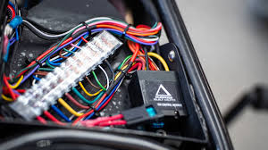
Select Wires and Protectors
For instance, using undersized or unshielded wiring in a high-temperature environment like an engine bay (where temperatures can reach 120°C or higher) can lead to insulation meltdown within months. A 22-gauge wire rated for only 60°C might fail catastrophically when subjected to 15A of current in a 90°C environment, while a proper 16-gauge cross-linked polyethylene (XLPE) insulated wire can handle the same load for over 10 years without degradation.
When selecting wires, prioritize stranded copper over solid core for flexibility and vibration resistance—typically 19 to 26 strands per conductor for automotive applications. For a 12V system, 14–16 AWG (1.6–2.0 mm²) wires are ideal for high-current paths like headlights or fans (carrying 15–20A), while 18–20 AWG (0.8–1.0 mm²) works for sensors and low-power signals (under 5A). For example, a 16 AWG wire with XLPE insulation (0.30–0.50 per meter) can safely carry 22A at 80°C, whereas a cheaper PVC-insulated version (0.15–0.25 per meter) might only handle 18A under the same conditions and crack over time in cold environments. For data lines (e.g., CAN bus), use twisted pair wires with a foil shield to reduce electromagnetic interference, maintaining a impedance of 120Ω ±10%.
Braided PET sleeving (costing ~0.50 per meter) offers abrasion resistance and flexibility, while corrugated conduit (usually nylon or polyethylene) provides crush protection but adds 3–5mm to the harness diameter. For high-heat zones, fiberglass or silicone sleeves (1–$2 per meter) withstand temperatures up to 200°C. Adhesive-backed clips should be rated for 50 N of pull strength and -40°C to 120°C operating ranges.
| Application | Recommended Wire Type | Insulation Material | Temp Rating | Cost per Meter | Protection Sleeving |
|---|---|---|---|---|---|
| High Current (e.g., Starter) | 12–14 AWG (2.0–3.3 mm²) | XLPE or Silicone | -40°C to 150°C | 0.60–1.00 | Fiberglass braid |
| General Power (e.g., Lights) | 16–18 AWG (1.0–1.6 mm²) | Cross-linked PVC | -40°C to 105°C | 0.30–0.50 | PET expandable sleeve |
| Sensors / Signals | 20–22 AWG (0.5–0.8 mm²) | PTFE or Teflon | -60°C to 200°C | 0.40–0.70 | Silicone spiral wrap |
| Data / Communication | 24 AWG twisted pair | Foil-shielded PVC | -20°C to 80°C | 0.80–1.20 | None (inherent shielding) |
Always factor in the total harness weight—a full automotive harness with 20 circuits might weigh 2.5 to 3.5 kg, so supports must be spaced every 150–200 mm. For waterproofing, use heat-shrink tubing with adhesive lining (3:1 shrink ratio, 120°C rating) at connectors. Testing shows that a properly selected and protected harness can last 10–15 years even in harsh conditions, while cutting corners may lead to failures within 12–24 months.
Test Before Finalizing
Industry data shows that over 40% of custom harness failures occur within the first 90 days due to undetected issues like poor crimps, insulation nicks, or voltage drop. For example, a single pin connector with just 5 mΩ of excess resistance can generate 2.5W of heat at 10A, enough to melt plastic housings in under 30 minutes. Testing isn’t just a final check—it’s a cost-saving measure that prevents recalls: reworking a fully installed harness takes 3-5x longer than fixing it on the bench, potentially adding 500 in labor costs per incident.
Begin with a visual inspection under 10x magnification to check for conductor fraying, insulation gaps, or imperfect crimps. Use a digital multimeter with 0.1% accuracy to measure resistance across each circuit—any reading above 0.5Ω per meter for 16-gauge wires indicates a problem. For continuity testing, apply 12V at one end and verify voltage drop is below 3% at the load point (e.g., ≤0.36V drop for a 12V system). High-current paths (15A+) should be stress-tested for 10 minutes while monitoring temperature with an IR gun; any terminal exceeding 60°C ambient + 20°C rise requires redesign.
Critical testing phases include:
- Insulation resistance test using a megohmmeter at 500VDC: readings below 20MΩ indicate moisture damage or pinched insulation.
- Vibration simulation at 10-200Hz frequency for 2 hours: any wire movement >1.5mm or connector loosening fails.
- Load cycling (50 cycles at max current): voltage stability must remain within ±5%.
- Water spray test (IP67 standard): check for >1MΩ resistance after 30 minutes of exposure.
For data lines, use an oscilloscope to verify signal integrity—CAN bus waveforms must show clean transitions with <2% overshoot and ring. Finally, label every tested circuit with a date code and tester ID. Document all measurements; a well-tested harness typically requires 45-60 minutes of validation but reduces field failure rates by up to 90%.
Designing a custom wiring harness, a nuanced electronics task, hinges on four data-driven steps: First, catalog devices with specs—e.g., 3 sensors needing 12V DC—to avoid mismatches. Second, measure routing paths with digital calipers (±1mm tolerance) for length accuracy. Third, select 18 AWG copper wires (600V insulation) and heat-shrink protectors for durability. Finally, test continuity at 12V DC to validate connections, ensuring reliability before finalization.
