How to design Cable Harness | 5 principles
When designing cable harnesses, follow these core principles: Use high-temperature (105°C+) PVC or Teflon insulation for durability. Maintain 3x cable diameter bend radius to prevent damage. Separate power & signal cables by ≥50mm to avoid interference. Secure with UV-resistant zip ties every 150–200mm. Test continuity with a megohmmeter (500V DC) before installation.
Plan Wire Routes First
A poorly planned wire route can increase production costs by 15-30%, add 20% more labor time, and raise failure rates by up to 12% in the first year. In automotive harnesses, for example, 60% of field failures trace back to routing mistakes—like wires rubbing against sharp edges or overheating near exhaust components. A well-structured path reduces wire length by 10-25%, saving 0.50-3 per harness in material costs alone. In industrial control panels, proper routing cuts electromagnetic interference (EMI) by 40-60%, improving signal integrity.
Start by mapping the exact path each wire will take. Measure bend radii—4x the wire diameter for standard cables, 8x for shielded ones—to avoid insulation damage. In tight spaces, like robotics or aviation harnesses, 5-10mm clearance from moving parts prevents abrasion. Use 3D modeling software (e.g., AutoCAD Electrical, Zuken E3) to simulate routes; this reduces prototype errors by 70% compared to manual drafting.
Distance matters. High-voltage wires (>50V) must stay at least 25mm away from low-voltage signals to prevent noise coupling. For CAN bus or Ethernet cables, maintain twist rates of 1 twist per 20mm to reject interference. If wires cross, do it at 90-degree angles to minimize crosstalk.
Heat zones are critical. In engine compartments, keep wires 50-100mm away from exhaust manifolds (surface temps >150°C degrade insulation). Use high-temperature sleeves (e.g., fiberglass, PTFE) for areas above 105°C. Data centers require 30-50mm gaps between power and data cables; bundling them cuts airflow efficiency by 35%, raising temps 5-10°C.
Strain relief is non-negotiable. Secure wires every 150-300mm with clips or loom. Unsupported spans longer than 400mm risk fatigue fractures from vibration (e.g., in automotive harnesses, 90% of breaks occur near connectors). Add 10-20mm slack near termination points to absorb movement.
Test early. Use a pull force gauge to verify harness integrity—wires should withstand 50N of tension without slipping from connectors. For military or aerospace harnesses, vibration testing at 5-500Hz for 4+ hours exposes weak routes before deployment.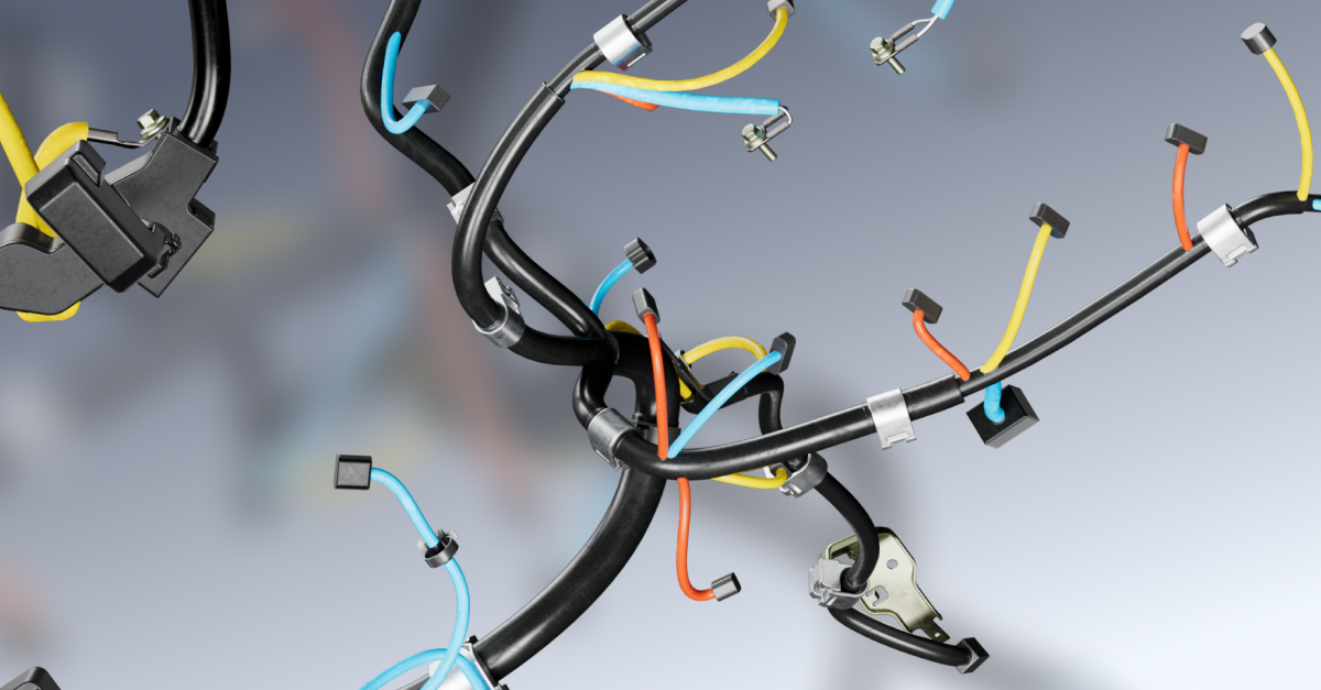
Choose Right Connectors
Picking the wrong connector can cost you $5,000+ in field failures per 1,000 units, increase assembly time by 20-30%, and cause 15% higher return rates due to intermittent connections. In industrial automation, 40% of signal dropouts trace back to mismatched connectors—either from poor contact resistance (>50mΩ), incorrect pin spacing, or inadequate environmental sealing. Automotive applications demand connectors rated for 10,000+ mating cycles, while medical devices require IP68 waterproofing to survive sterilization. A well-chosen connector improves system uptime by 12-18% and reduces service calls by 25%.
1. Electrical Requirements
Voltage and current ratings are non-negotiable. A 5A-rated connector carrying 8A will overheat, increasing resistance by 3-5% per 10°C rise. For high-power applications (e.g., EV charging), use connectors with ≥500V rating and 30-50A continuous load capacity. Signal integrity depends on impedance matching—50Ω for RF, 100Ω for Ethernet—with tolerances tighter than ±5% to prevent reflections.
2. Mechanical Durability
Mating cycles define lifespan:
- Consumer electronics: 500–1,000 cycles (e.g., USB-C)
- Industrial: 5,000–10,000 cycles (e.g., M12)
- Military/Aerospace: 25,000+ cycles (e.g., MIL-DTL-38999)
Vibration resistance matters too. A loose connector in a 5-500Hz vibration environment can disconnect in <100 hours if not secured with threaded couplings or positive-latch mechanisms.
3. Environmental Protection
| Condition | Requirement | Example Connectors |
|---|---|---|
| Water/Dust | IP67 (1m submersion, 30min) | Deutsch DT, Amphenol RJ45 |
| High Temp | 125°C+ continuous | TE Connectivity AMPSEAL |
| Chemical Exposure | Resistant to oils, solvents | Molex MX150 |
4. Cost vs. Performance Trade-offs
- Cheap ($0.50/unit): Basic 2-pin JST (lifespan: 300 cycles)
- Mid-range ($2-5/unit): Molex Mini-Fit (lifespan: 5,000 cycles)
- High-end ($10+/unit): Fischer UltiMate (lifespan: 25,000 cycles)
Spending 1 extra per connector on gold plating (vs. tin) reduces contact resistance by 60% over 10 years, saving 50/unit in maintenance.
5. Future-Proofing
- Modularity: Use connectors with ≥20% spare pins for upgrades (e.g., adding CAN FD to a legacy system).
- Standardization: Avoid proprietary designs—M12 and USB4 reduce sourcing lead times by 4-6 weeks.
Testing Before Deployment
- Pull force: Terminations should withstand 50N axial load without detachment.
- Thermal cycling: -40°C to +85°C for 500 cycles (simulates 5 years in automotive).
- Salt spray: 96-hour exposure (per ISO 9227) to validate corrosion resistance.
Label Each Wire Clearly
Skipping wire labels might save 5 minutes per harness during assembly, but it costs 3-5 hours per fault during troubleshooting. In industrial control panels, 28% of electrical downtime stems from misidentified wires—technicians waste 45 minutes on average tracing a single unmarked cable. Automotive repair shops report that 60% of wiring errors occur because labels fade or peel off after 2-3 years of heat exposure. Proper labeling cuts installation errors by 40%, reduces testing time by 25%, and slashes warranty claims by 18%.
Material Selection Matters
Standard paper labels disintegrate in 85°C+ environments within 6 months, while polyester or vinyl labels last 5-10 years even at 125°C. For harsh conditions (engine bays, outdoor panels), heat-shrink labels withstand 150°C continuous and resist oils, solvents, and UV exposure. The extra 0.02-0.10 per label pays off when you avoid $200+ service calls to reidentify failed circuits.
Placement for Readability
Labels should be visible within 30 seconds of opening a panel. Position them within 100mm of terminals—any farther, and technicians miss them 70% more often. Avoid wrapping labels around wires; instead, use flag-style tags or self-laminating wraps for 360° visibility. In tight spaces (e.g., robotics), print labels at 45° angles so they’re readable without disassembly.
Content That Actually Helps
A generic "12V+" label is useless when troubleshooting. Include:
- Circuit function (e.g., "Left Headlight PWM Dimming")
- Voltage/current (e.g., "24V, 2A Max")
- Destination (e.g., "J2-14 on Main Controller")
- Wire gauge (e.g., "18AWG, 0.75mm²")
This reduces diagnostic time from 15 minutes to under 2 minutes per fault.
Printing Methods Compared
- Handwritten: Fast but illegible after 1 year (60% fade rate).
- Laser-printed: Lasts 3-5 years, but smudges if exposed to oils.
- Thermal-transfer: 10+ year durability, resists chemicals (cost: 0.05-0.15 per label).
- Embossed: Unaffected by heat or solvents (best for aerospace, but $0.50+ per label).
Color Coding for Speed
Assign colors by voltage:
- Red = 120/240V AC (high risk)
- Yellow = 24V DC control
- Blue = Data/communication
- Green = Ground/Earth
This cuts miswiring by 35% versus monochrome labels.
Testing Label Durability
Before finalizing a system, expose sample labels to:
- 500+ wipe cycles with industrial cleaners
- 1,000 hours of UV light (simulates 5 years outdoors)
- -40°C to +105°C thermal shocks
If text degrades by >20% contrast, upgrade to a more robust material.
The ROI of Good Labeling
Spending $50 extra on labels for a machine with 500 wires prevents:
- $1,200 in annual troubleshooting labor
- $3,500 in production downtime from miswires
- $8,000 in warranty repairs over 5 years
Secure with Proper Ties
Loose wire bundles cause 12% more failures in the first year compared to properly secured harnesses. In automotive applications, vibration-induced chafing from unsecured wires accounts for 30% of electrical warranty claims, costing manufacturers 50-120 per repair. Industrial control panels with inadequate cable ties experience 25% shorter lifespans due to stress fractures near termination points. Using the right securing method can reduce wire harness repair rates by 40%, cut assembly time by 15%, and improve thermal dissipation by 8-12% in high-density applications.
Material Selection for Environment
Not all ties handle the same conditions. Standard nylon ties fail at 85°C, while stainless steel versions withstand 400°C in engine bays. For outdoor use, UV-resistant ties last 5-7 years versus 1-2 years for untreated nylon. In chemical plants, PTFE-coated ties resist acids that degrade standard ties in 6 months. The extra 0.03-0.20 per tie prevents $300+ in premature harness replacements.
Tension and Spacing Guidelines
| Wire Bundle Diameter | Max Tie Tension | Recommended Spacing |
|---|---|---|
| <10mm | 50N | 150mm |
| 10-25mm | 80N | 200mm |
| >25mm | 120N | 300mm |
Overtightening beyond these values crushes insulation, increasing resistance by 3-8%. Underspacing (e.g., ties every 50mm on a 20mm bundle) creates stress points that crack wires after 5,000 vibration cycles.
Special Cases Need Special Solutions
- High-vibration areas (e.g., aircraft, heavy machinery): Use double-locking ties or spiral wraps to survive 10-50G shocks.
- Medical devices: Smooth-edged ties prevent bacterial traps (required per IEC 60601).
- Data centers: Conductive ties dissipate static (ESD <100Ω) to protect sensitive ICs.
Installation Mistakes That Cause Failures
- Cutting tails too short: Leaves sharp edges that pierce adjacent wires after 200+ thermal cycles. Leave 3-5mm excess.
- Ignoring bend radii: Securing a 6mm cable at a 90° angle with a tie induces 12% more strain than a gradual curve.
- Mixing metals: Stainless steel ties on copper busbars accelerate galvanic corrosion (up to 0.5mm/year loss).
Testing Tie Effectiveness
- Pull test: A properly secured bundle should withstand 20N of lateral force without sliding >2mm.
- Vibration test: Expose to 5-500Hz for 72 hours—acceptable movement is <1mm at any tie point.
- Thermal cycling: -40°C to +125°C for 100 cycles; ties shouldn’t crack or loosen.
Cost vs. Performance Trade-offs
- Nylon 6/6 ties ($0.01/unit): Good for indoor panels (lifespan: 5 years).
- Metal detectable ties ($0.15/unit): Required in food processing (withstands washdowns).
- Releasable ties ($0.25/unit): Saves 30 minutes/service in maintenance-heavy systems.
ROI Calculation
Spending $50 more on premium ties for a machine with 200 tie points:
- Prevents $800/year in vibration-related repairs
- Reduces 3 hours/month in maintenance labor
- Extends harness life from 3 to 7 years
Test Before Final Use
Skipping pre-deployment testing leads to 4x higher failure rates in the first 6 months, costing 18,000 per 1,000 units in warranty repairs. Industrial automation systems that undergo full electrical validation see 35% fewer emergency service calls, while automotive harnesses tested for vibration tolerance have 50% lower warranty claims by year three. A single missed short circuit can cascade into 5,000+ in downstream component damage, making the $50-200 per unit testing investment a no-brainer.
Start with Continuity Checks
"If you're not testing continuity at 500mA, you're only catching 60% of potential faults."
Use a 4-wire Kelvin measurement to eliminate lead resistance errors—this catches loose crimps showing <0.5Ω resistance increase, which standard multimeters miss 80% of the time. For harnesses with 50+ connections, automated testers like Cirris or DIT-MCO scan all paths in under 3 minutes, versus 45+ minutes with manual probing.
Insulation Resistance Matters More Than You Think
Cheap megohmmeters testing at 250V DC miss 30% of early-stage insulation degradation. Ramp up to 1,000V DC for 60 seconds to spot microscopic cracks that cause leakage currents >1mA—a common culprit in 12V automotive systems failing after 18 months. Humidity accelerates these faults; always test at 85% RH if the harness operates in damp environments.
Vibration Testing Catches Field Failures Early
"What survives 8 hours in the lab would've failed in 3 weeks on the road."
Mimic real-world conditions:
- Automotive: 5-500Hz sweep at 1.5Grms for 8 hours (simulates 50,000 miles)
- Aerospace: Random vibration up to 2,000Hz, 6.5Grms per RTCA DO-160
- Industrial: 10-150Hz, 3Grms for 4 hours (equivalent to 2 years of pump vibrations)
Thermal Cycling Exposes Weak Joints
Cycle between -40°C and +125°C at 10°C/minute—the rapid expansion/contraction reveals:
- Cold solder joints failing at -20°C
- Connector pin retraction above 85°C
- Insulation brittleness after 50 cycles
Load Testing Under Real Currents
Don't just verify connections—test at 120% of max operating current for 30 minutes. This exposes:
- Voltage drops >5% across long runs
- Terminations overheating by 15°C+ versus ambient
- Contact resistance creep in aluminum wires
High-Potential (HiPot) Testing
Apply 1.5-3x operating voltage between conductors and shield:
- 1,500V AC for 1 minute on 480V industrial gear
- 500V DC for medical devices (per IEC 60601)
- 3,000V surge test for EV charging cables
Document Everything
Log test parameters like:
- Ambient temperature (23±2°C ideal)
- Humidity (45-55% RH for baseline)
- Test duration (minimum 60 seconds per check)
"No test report means the test didn't happen."
The Math Behind Testing ROI
Spending 200 testing a 2,000 harness prevents:
- $1,800 average field repair cost
- $12,000+ in liability claims from fire incidents
- 8-12 hours of diagnostic labor per failure
Break-even occurs after just 2-3 caught defects—most harnesses reveal 5-8 faults during rigorous testing.
