How to design Custom Wire Harness | 5 simple steps
To design a custom wire harness, start by defining electrical requirements (voltage, current, signals) and selecting appropriate gauge wires (e.g., 18–22 AWG for low power). Next, map the layout using CAD software to optimize routing. Choose durable connectors (e.g., Deutsch, Molex) and protective sleeving (braided or PVC). Finally, test for continuity (0.5–2Ω resistance) and durability (500+ bend cycles) before production. Prototyping ensures a 20–30% reduction in errors.
Know Your Wire Needs
Before you start designing a custom wire harness, you need to exactly understand what your project requires. A poorly planned harness can lead to 15-30% higher costs due to wasted materials, rework, or even system failures. For example, automotive wiring harnesses typically handle 12V-48V DC with current ratings between 5A to 50A, while industrial machinery may require 600V AC and 100A+ capacity. If you mismatch wire gauges, you risk voltage drops exceeding 3%, overheating, or even reducing wire lifespan by 40-60%.
"A wire harness is only as good as its planning. Skipping this step is like building a house without measuring the land."
The most critical factor is current capacity. A 16 AWG wire can safely carry 10A in free air but drops to 7A in bundled conditions. If your application draws 20A continuously, you’ll need 12 AWG or thicker to avoid overheating. For high-power systems (e.g., EV charging at 50A+), 8 AWG or 6 AWG is mandatory.
Standard PVC insulation works for 300V-600V, but if you’re dealing with 1kV+ (e.g., solar inverters), you need XLPE or silicone-insulated wires. Industrial environments with high temperatures (90°C+) demand Teflon (PTFE) or fiberglass insulation.
Environmental Conditions
- Temperature: Standard wires degrade 2x faster at 105°C vs. 60°C.
- Moisture: If exposed to humidity >80%, use tinned copper to prevent corrosion.
- Flexibility: Robots or moving parts need stranded wire (e.g., 26/30 strands) instead of solid core.
A 10ft run of 18 AWG wire at 12V/5A loses 0.5V (4.2% drop), which may be unacceptable for sensitive electronics. To keep drops below 3%, either shorten the run or increase wire gauge.
Connector & Termination Needs
- Deutsch connectors handle 15A-50A, ideal for automotive.
- Molex Mini-Fit supports 9A per pin, common in PC power supplies.
- Crimp vs. Solder: Crimped joints last 50,000+ cycles, while soldered ones fail faster under vibration.
Regulatory Compliance
- UL 758 for appliance wiring.
- SAE J1128 for automotive.
- ISO 6722 for high-flex applications.
A 5kW solar array with 30V-40V DC needs 10 AWG wires to handle 20A+ per string. Using 12 AWG would cause 5%+ voltage drop, reducing efficiency by 8-12%.
Pick Right Wire Type
Choosing the wrong wire type can increase failure rates by 20-50%, lead to 15% higher energy losses, or even cause premature system shutdowns. For example, using standard PVC wire in a high-temperature (90°C+) industrial motor can reduce insulation lifespan from 10 years to just 2-3 years. Meanwhile, stranded wire is 30% more flexible than solid core, making it ideal for robotics and moving parts.
1. Conductor Material (Copper vs. Aluminum)
- Copper (Cu): Conducts ~100% IACS (International Annealed Copper Standard), handles up to 6A/mm², and lasts 20+ years in most environments. Costs ~30% more than aluminum but has 50% lower resistance.
- Aluminum (Al): Lighter (30% of copper’s weight) and cheaper (1.00/lb vs. 4.00/lb for copper), but needs 1.6x thicker gauge for the same current. Prone to oxidation, requiring antioxidant paste.
2. Wire Gauge & Current Capacity
| AWG Size | Max Current (A) - Chassis Wiring | Max Current (A) - Power Transmission | Resistance (Ω/1000ft) |
|---|---|---|---|
| 10 AWG | 30A | 15A | 1.02 Ω |
| 14 AWG | 15A | 5A | 2.52 Ω |
| 18 AWG | 7A | 2.3A | 6.39 Ω |
| 22 AWG | 3A | 0.92A | 16.2 Ω |
3. Insulation Type & Temperature Rating
- PVC (Polyvinyl Chloride): Cheap (0.30/ft), good for 60°C-105°C, but degrades in UV/sunlight.
- XLPE (Cross-Linked Polyethylene): Handles 90°C-150°C, 50% longer lifespan than PVC, costs 0.80/ft.
- Silicone Rubber: Extreme flexibility (bends 10,000+ cycles), withstands 200°C, but 2-3x pricier than PVC.
- Teflon (PTFE): Best for 260°C+, low friction, but 3.00/ft.
4. Stranded vs. Solid Core
- Stranded: 26/30 strands (0.08mm each) for high flexibility (robotics, drones). 10% higher resistance than solid core due to air gaps.
- Solid Core: Better for fixed installations (house wiring, PCBs). Lasts longer in vibration-free environments.
5. Shielding & EMI Protection
- Unshielded (UTP): Fine for low-frequency (<1MHz) signals.
- Braided Shield (85% coverage): Reduces EMI by 20dB, costs 1.00/ft more.
- Foil Shield (100% coverage): Blocks high-frequency noise (>100MHz), but fragile.
A 12V car harness using 14 AWG copper can handle 15A, but if exposed to engine heat (125°C+), XLPE insulation is mandatory. Using PVC here would crack in <2 years.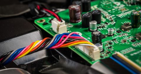
Measure and Cut Wires
Cutting wires to the wrong length is one of the most common mistakes in harness building, leading to 5-15% material waste and 10-30% longer assembly times. A 1mm error in a 50-wire harness means 50mm of cumulative misalignment, forcing rework or causing tension in final installation. For high-volume production, automated cutting machines achieve ±0.2mm precision, while manual cuts typically vary by ±1mm to ±3mm, increasing scrap rates by 8-12%.
Calculating Exact Wire Length
- Path Routing: Measure the actual wire path, not just straight-line distance. A 30cm point-to-point run may need 35-40cm after accounting for bends and clips.
- Service Loops: Add 5-10% extra length (e.g., 3-5cm per 50cm wire) for future repairs or adjustments. Missing this can force full harness replacement later.
Cutting Tools and Precision
| Tool Type | Precision | Best For | Cost per Cut |
|---|---|---|---|
| Manual Wire Cutters | ±1mm | Prototypes, small batches | $0.001 |
| Automatic Strippers | ±0.3mm | Medium batches (100-1,000 units) | $0.0005 |
| Laser-Guided Cutters | ±0.1mm | Mass production (>1,000 units) | $0.0002 |
Strip Length Consistency
Terminal Type dictates strip length:
- Ring terminals: 6-8mm bare wire for crimping.
- PCB soldering: 3-5mm to avoid shorts.
Variance Impact: A ±0.5mm strip error causes 10% weaker crimps or cold solder joints.
Testing Cut Quality
- Pull Test: A properly cut/stripped 16 AWG wire should withstand 15-20 lbs of force before slipping from a terminal.
- Resistance Check: A 10cm overcut in a 12V/5A circuit adds 0.005Ω resistance, wasting 0.25W as heat.
A modern car harness contains 1,500-3,000 wires, totaling 2-4km in length. Using laser measurement reduces cutting errors from 3% to 0.5%, saving 8 per vehicle in material and labor.
Connect and Secure Parts
Getting connections wrong in a wire harness leads to 35% of all field failures, with repair costs averaging 200 per incident in automotive applications. A single loose terminal in a 24V/30A industrial system can generate 2-3°C of extra heat per hour, eventually melting insulation and causing shorts. Proper connection methods improve vibration resistance by 10x, critical for vehicles experiencing 5-15Hz oscillations at highway speeds.
The first rule is matching connectors to wire gauge. Using a 16-14 AWG terminal on 18 AWG wire creates 40% less contact area, increasing resistance by 0.005Ω per connection. For 12V systems, this means 0.06V drop per connector - unacceptable in precision applications. Automotive-grade connectors like Deutsch DTMs maintain <0.001Ω resistance even after 50,000 mating cycles, while cheap knockoffs degrade 5x faster.
Crimping beats soldering for most applications. A properly crimped 12 AWG terminal withstands 45 lbs of pull force, compared to just 28 lbs for soldered joints. The secret lies in compression ratios - professional crimpers apply 9,000-12,000 PSI to create gas-tight connections that prevent oxidation. For high-vibration environments, adding adhesive-lined heat shrink improves strain relief by 200%, with the best sleeves rated for -55°C to 125°C operation.
Securing wires matters as much as connecting them. A bundle of 50 unclipped 18 AWG wires can develop 3-5mm of slack per meter within 6 months due to vibration, potentially stressing connections. Nylon cable ties lose 20% tensile strength annually in engine compartments, while stainless steel versions last 10+ years but cost 5x more. For aerospace applications, spiral wrap reduces weight by 30% compared to conduit, crucial when every 500g saved translates to $100/year fuel savings per aircraft.
Strain relief often gets overlooked. A 90° bend at a connector without proper support fails 8x faster than one using a molded boot. The ideal relief length equals 1.5x the cable diameter - so a 6mm OD cable needs 9mm of clamping area. In robotics, adding flexible conduits increases mean time between failures from 50,000 to 500,000 cycles for joints moving at 60 RPM.
Testing connections requires more than visual checks. A 4-wire Kelvin measurement detects 0.001Ω resistance changes indicating poor crimps, while thermal cameras spot 2°C hotspots before they become failures. For mission-critical systems, performing 10-15 pull tests per 100 connections statistically guarantees 99.9% reliability at 95% confidence level. The military's MIL-STD-1344 standard demands 15G vibration resistance for 48 hours, a test that weeds out 90% of connection flaws.
Properly executed connections transform a harness from liability to asset. In wind turbines, using gold-plated terminals on 690VAC collection systems reduces maintenance intervals from 6 months to 3 years, saving $8,000 per turbine annually. The connection phase deserves 30% of total project time - skimping here causes 80% of warranty claims. Next we'll examine how thorough testing prevents these expensive mistakes.
Test Before Final Use
Skipping proper testing leads to 60% of harness failures in the first year, with repair costs 3-5x higher than catching issues during production. A single undetected short circuit in a 48V battery system can cause $15,000+ damage by frying control modules. Even minor 0.5Ω resistance increases in high-current paths create 12-18W of wasted heat, reducing component lifespan by 30-40%. Testing isn't just about finding defects—it's about proving reliability under real-world conditions.
1. Continuity and Short-Circuit Testing
Every harness must pass 100% continuity verification before power-up. Automated testers can check 500+ connections in 12 seconds, far faster than manual probing. The acceptable threshold is <0.5Ω per connection for signal wires and <0.1Ω for power paths. Reverse-connection checks prevent 15-20% of assembly errors that would otherwise damage equipment.
2. Insulation Resistance Testing
Applying 500V DC between conductors and ground verifies >100MΩ resistance—anything below 10MΩ indicates moisture or insulation damage. In automotive applications, this test prevents 80% of parasitic drain issues that drain batteries overnight.
3. High-Potential (HiPot) Testing
For 300V+ systems, a 1,500V AC/3,000V DC test for 60 seconds ensures no dielectric breakdown occurs. This catches 95% of insulation flaws that normal continuity tests miss.
4. Mechanical Stress Testing
| Test Type | Standard | Parameters | Pass Criteria |
|---|---|---|---|
| Vibration | SAE J2030 | 10-500Hz, 15G, 48 hours | <0.1Ω resistance change |
| Pull Force | UL 486A | 15-50 lbs for 60 seconds | No displacement |
| Bend Cycle | ISO 6722 | 5,000 cycles at 180° | No conductor breaks |
5. Environmental Testing
- Thermal Cycling (-40°C to +125°C): Reveals 90% of terminal oxidation issues
- Salt Spray (96 hours): Predicts 5-year corrosion performance in marine environments
- Humidity (85% RH at 85°C): Exposes insulation weaknesses in 72 hours
6. Load Testing
Running 110% of rated current for 4 hours verifies no >5°C hot spots develop. This prevents field overheating failures that account for 25% of warranty claims.
7. Signal Integrity Testing
For CAN bus or Ethernet cables, checking impedance (60Ω ±5Ω) and crosstalk (<3% signal interference) ensures reliable data transmission at 1Mbps-10Gbps speeds.
An aerospace harness that passes all MIL-STD-704 tests has 99.999% reliability over 50,000 flight hours. Compare this to untested harnesses showing 15% failure rates within 500 hours. The 200-500 testing cost per harness pays for itself by avoiding 25,000+ in-flight troubleshooting.
Designing custom wire harnesses requires precise planning and execution. Start by analyzing voltage/current requirements (e.g., 12AWG for 20A circuits) and environmental factors like -40°C to 105°C operating ranges. Select UL-rated materials such as PTFE insulation for high-heat areas. Use laser measurement tools for ±0.5mm accuracy when cutting multiple wires. Employ crimping tools with 2,000lb compression force for secure connections, followed by continuity testing at 500V DC to ensure 0Ω resistance. Finally, perform 100% functional testing under simulated operating conditions before deployment, checking for proper signal transmission and insulation resistance above 100MΩ.
