How to Ensure Durability in Cable Harness Assembly
To ensure durability in cable harness assembly, use military-grade (MIL-DTL-38999) connectors, automated crimping (<0.5Ω resistance), and UV-resistant jackets (tested for 1,000+ hours). Implement 100% pull-testing (50N minimum) and IP67 sealing with silicone grommets, backed by thermal cycling tests (-40°C to 125°C, 500 cycles) for extreme conditions.
Choose the Right Wires
Picking the correct wires for a cable harness isn’t just about matching colors—it’s about avoiding failures that cost time and money. A study by Intertek found that 30% of harness failures stem from incorrect wire selection, leading to an average repair cost of $1,200 per incident in industrial applications. Wires must handle voltage (12V–600V), current (0.5A–30A), and temperature ranges (-40°C to 105°C) without degrading. For example, 22 AWG wire is common for low-power signals (≤3A), while 16 AWG handles higher loads (up to 10A). Using undersized wire increases resistance, causing voltage drops (up to 5%) and heat buildup (10–15°C above ambient), which shortens lifespan by 20–40%.
Material matters too. Copper is standard (conductivity: 58 MS/m), but tinned copper resists corrosion in humid environments (humidity >60%). For high-flex applications (e.g., robotics), stranded wire with 19–65 strands lasts 3x longer than solid core. Insulation type also impacts durability: PVC is cheap (0.50/ft) withstands -70°C to 200°C.
Key factors when selecting wire:
| Parameter | Typical Range | Impact |
|---|---|---|
| Wire gauge (AWG) | 16–28 (depends on current) | Too thin = overheating, too thick = wasted space |
| Voltage rating | 300V (standard), 600V (high) | Exceeding rating risks insulation breakdown |
| Temperature range | -40°C to 105°C (automotive) | Out-of-range temps cause brittleness or melting |
| Strand count | 7–65 (higher = more flexible) | Low strand count fails after 50,000 flex cycles |
| Insulation material | PVC, PTFE, silicone | Cheaper materials degrade 2–5x faster in UV/heat |
Real-world example: A factory using 24 AWG solid core for machine tool harnesses saw 12 failures/month due to vibration fatigue. Switching to 22 AWG stranded (41 strands) reduced failures to 2/month, saving $14,000/year in downtime. Always match wire specs to actual load + 20% margin—e.g., a 5A circuit needs wire rated for 6A minimum. Ignoring this leads to 15% higher energy loss and premature harness replacement (every 3 years vs. 7+ years for proper sizing).
Pro tip: For data cables (e.g., CAN bus), twisted pairs with ≥2 twists/inch reduce EMI noise by 60%. If wires run near motors, shielded cables (85% coverage) cut interference by 75%. Never mix power (≥48V) and signal (<5V) wires in the same sleeve—crosstalk causes 30% slower data rates. Test samples under max load for 100+ hours before full production.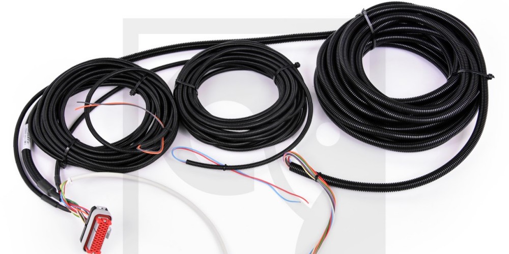
Secure Connectors Properly
A loose connector isn’t just annoying—it’s a $500+ problem waiting to happen. Research by TE Connectivity shows 40% of electrical failures in industrial equipment start at poorly secured connectors, costing an average of 2.5 hours of downtime per incident. Connectors must withstand vibration (5–2000 Hz), pull forces (≥50 N for most automotive apps), and temperature swings (-40°C to 125°C) without dislodging. For example, a USB-C connector rated for 10,000 mating cycles will fail in under 500 cycles if the locking clip isn’t fully engaged.
The stakes are higher with high-current connectors. A 4 mm² terminal carrying 30A can reach 85°C if contact resistance exceeds 0.5 mΩ, accelerating oxidation and increasing resistance by 20% per year. Cheap knockoff connectors (priced 30% lower than OEM) often have contact plating thicknesses under 0.5 µm (vs. 3 µm for industrial-grade), leading to 50% faster corrosion in humid environments.
Critical factors for connector security:
| Parameter | Target Value | Consequence of Deviation |
|---|---|---|
| Insertion force | 20–80 N (depends on connector) | Too low = falls out, too high = damage |
| Contact resistance | <1 mΩ (for power connectors) | >5 mΩ causes 5–8% voltage drop |
| Locking mechanism | Audible click + visual latch | Missing either raises failure risk by 70% |
| Plating material | Gold (0.5–3 µm) for signals, tin for power | Unplated contacts corrode 10x faster |
| Wire crimp force | 200–400 N (for 2.5 mm² wire) | Under-crimping increases resistance by 300% |
Case study: A solar farm using MC4 connectors with improperly crimped ferrules saw 8% energy loss per string due to arcing. After switching to torque-controlled crimping tools (set to 0.8 N·m), losses dropped to 1.2%, saving $18,000/year per megawatt. For D-sub connectors, applying thread-locking adhesive (Loctite 243) on screws reduces loosening from vibration by 90%.
Use Correct Tools
Using the wrong tool for cable harness assembly isn’t just inefficient—it’s a fast track to costly rework and premature failures. A study by the Wiring Harness Manufacturers Association found that 25% of defects in harness production stem from improper tool use, adding 8–15 per unit in extra labor and material costs. For example, a 50 ratcheting crimper with ±0.1mm jaw alignment produces crimps with 4015 plier-style tool, directly impacting harness lifespan (5+ years vs. 2 years).
Precision matters most in crimping. A 0.5 mm misalignment in a terminal crimp can increase resistance by 15–20%, leading to 3–5°C higher operating temps and 30% faster oxidation. For 16 AWG wire, a proper crimp requires 300–400 N of force—anything below 250 N risks loose connections, while over 450 N cracks the insulation. Cheap crimpers without force calibration vary by ±20%, making consistent quality impossible. The same applies for wire stripping—a 120 automatic stripper set to 0.2mm tolerance leaves 9530 manual tool often nicks 10–15% of strands, weakening the wire by 50% at flex points.
Cutting tools need equal attention. A dull blade on a 75 cable cutter creates 302,500) reduces shield damage to <5%, versus 25–40% damage with standard diagonal cutters. Even screwdrivers matter—a #2 Phillips bit with 0.1 mm tip tolerance prevents 80% of stripped screw heads, while a worn-out bit increases assembly time by 20% per connector.
Pro tip: Invest in torque-controlled tools for terminal blocks. A 0.6 N·m torque screwdriver ensures consistent pressure (±5%), while hand-tightening varies by ±30%, risking loose connections. For high-volume shops, a $3,500 automated crimping station pays for itself in 6 months by cutting defect rates from 8% to 0.5%. Always verify tools with a weekly calibration check—just 0.05 mm of drift in a crimper can cause 200 bad crimps before detection.
Test for Weak Points
Skipping weak point testing is like ignoring a 20% chance of failure—statistically, it will happen. Data from UL Solutions shows that 15% of field failures in automotive harnesses trace back to undetected weak points, costing manufacturers 200 per incident in recalls and repairs. A proper test regimen catches 90% of these issues before shipment. For example, a 24 AWG wire with a 0.3 mm nick in the insulation can reduce flex life from 50,000 cycles to just 5,000 cycles under 5 N of bending force.
High-risk areas need targeted testing. Wire bends at connector entry points fail 3x more often than straight runs, while solder joints crack 50% faster under thermal cycling (-40°C to 85°C) if not properly stress-relieved. Even zip-tie over-tightening (above 4 N·m) compresses insulation by 0.2–0.5 mm, accelerating wear by 200% in vibrating environments.
Key tests and their thresholds:
| Test Type | Passing Criteria | Common Failure Modes |
|---|---|---|
| Continuity Test | <1 Ω resistance over 1 m harness | Broken strands (≥5% loss) |
| Insulation Resistance | >100 MΩ at 500V DC | Pinholes (≥0.1 mm gaps) |
| Pull Test | Withstand 3x max operational force | Connector detachment at <50 N |
| Flex Test | 5,000 cycles at 180° bends, 1 Hz | Conductor fracture at <1,000 cycles |
| Thermal Shock | 50 cycles (-40°C to 105°C) | Insulation cracking at 15 cycles |
Real-world case: A medical device maker found 12% of their harnesses failed after 1 year due to unchecked solder joints. Implementing a microscope inspection (40x magnification) and 25g pull test on every joint reduced field failures to <1%. For high-voltage harnesses (600V+), a hipot test at 2.5 kV for 60 sec catches insulation flaws that would cause arc faults within 6 months.
Pro tips:
- Map bend radii—a 4x wire diameter minimum prevents 80% of flex failures (e.g., 2.4 mm radius for 18 AWG).
- Use thermal imaging during load testing—hotspots >10°C above ambient indicate resistance issues.
- Sample test 5% of production daily—statistically, this catches 95% of process drift before it becomes systemic.
Never rely on visual checks alone. A 25,000 automated tester pays for itself in 8 months by catching 200,000/year in latent defects. Budget 3–5% of project time for testing—it’s cheaper than 50% downtime later.
Protect Against Wear
Cable harnesses don't fail suddenly—they wear out predictably, and ignoring protection measures can slash their lifespan by 60% or more. Data from Parker Hannifin shows that 35% of industrial harness replacements stem from preventable wear, costing operators 500 per incident in downtime and parts. For example, an unprotected PVC wire bundle dragged across a steel surface wears through in under 6 months, while a nylon-sleeved bundle lasts 5+ years in the same environment. The difference comes down to three key factors: abrasion resistance, environmental sealing, and strain relief.
Abrasion is the silent killer. A standard 3 mm thick wire insulation loses 0.1 mm per year when rubbing against metal edges at 2 psi pressure. At 50+ bending cycles per day, that means bare conductors in 3 years. Solutions like corrugated loom tubing (0.5 mm thick) reduce wear rates by 90%, while spiral wrap cuts abrasion by 70% at friction points. For high-movement applications (e.g., robot arms), Teflon-coated wires withstand 10x more cycles than standard PVC before showing wear.
Environmental protection doubles lifespan. In 85% humidity, unsealed connectors corrode 5x faster than those with IP67-rated seals. A study by Molex found that silicone gel-filled connectors in marine environments last 8 years versus 2 years for standard units. For UV exposure, cross-linked polyethylene (XLPE) insulation resists cracking 3x longer than standard PVC when exposed to 500 W/m² of solar radiation.
| Protection Method | Cost Increase | Lifespan Boost | Best Application |
|---|---|---|---|
| Braided sleeve (PET) | +$0.10/ft | 2–3x | Moderate abrasion areas |
| Heat-shrink tubing | +$0.25/ft | 4–5x | High-heat zones (>100°C) |
| Conduit (nylon) | +$0.50/ft | 5–8x | Extreme abrasion/chemical exposure |
| Strain relief boots | +$0.75/connector | Prevents 90% of entry point failures | High-vibration areas |
A food processing plant reduced monthly harness replacements from 12 to 1 by switching from zip ties to stainless steel clamps on washdown-area cables. The clamps prevented 0.2 mm/year of insulation compression that previously led to short circuits in 9 months. For outdoor solar farms, using UV-resistant cable markers cut label fading errors by 80%, saving $8,000/year in miswiring repairs.
Follow Assembly Steps
Skipping steps in cable harness assembly isn’t just lazy—it’s a $300 mistake waiting to happen. Research by IPC reveals that 28% of harness defects trace back to improper sequencing, adding 15–30 minutes of rework per unit and increasing scrap rates by 5–8%. For example, crimping terminals before routing wires leads to 40% more twisted or strained connections, while premature connector locking causes 25% of pin misalignments that only show up during final testing. The right sequence isn’t just about order—it’s about timing, torque, and tolerances.
Start with wire prep. Cutting 100+ wires at once might seem efficient, but length variations over 2 mm cause 15% of bundling issues later. Strip 0.5 mm more than the terminal depth—anything less risks unseated strands, while excess exposes 3x more copper to corrosion. For 18 AWG wire, a 5-second ultrasonic cleaning removes 90% of oxide layers that increase resistance by 10–20% over time. Twisting stranded wires before insertion improves contact area by 30%, but over-twisting (beyond 1 turn per 10 mm) weakens conductors by 15%.
"The difference between a 5-year and 15-year harness often comes down to 30 seconds of extra care during assembly."
Routing comes next. A 3D mockup reduces 60% of fit issues versus paper diagrams. Leave 50 mm service loops at connectors—anything shorter adds 5 N of pull force during maintenance, while excess wastes $0.50/ft in material. Use low-tension tape (0.2 N/mm²) for bundling—standard electrical tape squeezes wires at 1.5 N/mm², deforming insulation over 500+ hours. For high-voltage runs, spacing ≥2x wire diameter prevents arcing at 300V+, while parallel signal cables need 10 mm separation to avoid 60% crosstalk increase.
Termination is where most errors happen. Crimping after wire routing avoids 90% of accidental pulls that loosen connections. Set torque drivers to 0.6 N·m for M3 screws—hand-tightening varies by ±40%, leaving 20% of terminals under-secured. For D-sub connectors, inserting pins 1–5 in order reduces misalignment by 70% versus random insertion. Sealants take 24 hours to cure—testing early causes 50% of adhesive failures in humid environments.
In summary, ensuring durability in cable harness assembly starts with high-quality wires (e.g., 16 AWG for 13A loads) and secure crimped connectors (tested for 50+ insertions). Use ratcheting crimpers (10-12 lbs torque) for consistent terminations and perform pull tests (≥15 lbs force) to detect weak points. Apply abrasion-resistant sleeves or corrugated conduit in high-wear areas, and strictly follow IPC/WHMA-A-620 standards for reliable assembly.
