How to Ensure Quality in Cable and Harness Assembly | 5 Tips
To install a custom engine wiring harness, start by aligning it with the engine’s routing channels (allow ±2mm length adjustment) and secure using 15-20cm-spaced nylon ties. Strip 8-10mm of insulation from terminals, crimp with 0.6N·m torque, then seal connections with 120-150°C heat-shrink tubing. Finally, test continuity (≤0.5Ω) and insulation resistance (≥100MΩ) per OEM specifications to confirm proper function.
Use Clear Design Drawings
Studies in manufacturing efficiency consistently show that projects utilizing fully-defined drawings see a 40% reduction in assembly errors and a 25% decrease in overall production time by eliminating guesswork and clarification delays. A single, ambiguous line on a schematic can lead to a batch of 500 units being wired incorrectly, resulting in costly rework, missed deadlines, and potential field failures. Investing an extra 5-10 hours in the detailed design phase can prevent hundreds of hours of corrective work later, offering a direct and significant return on investment.
-
Prevents incorrect wire routing and connector termination.
-
Serves as a critical reference for quality assurance checks.
-
Drastically reduces assembly time and material waste.
For each wire, the drawing must explicitly call out the wire gauge (e.g., 22 AWG for signals under 1A, 16 AWG for power lines over 5A), its insulation material (e.g., PVC for 80°C environments, Tefzel for 150°C or high-flex cycles), and its precise color. Using a unique color for every circuit is ideal, but when duplicates are necessary, the use of tracer stripes (e.g., blue with a white stripe) must be explicitly defined to avoid confusion between a solid blue and a blue-with-stripe wire.
This goes beyond a simple schematic and includes a scale drawing or 2D/3D layout showing the exact length of each wire branch, accurate to within ±0.5mm for critical lengths. It must specify the location and type of every tie-wrap, sleeve, or conduit, including their material (nylon, silicone) and minimum tensile strength (e.g., 50 lb). For connectors, the drawing must provide the manufacturer part number (e.g., Molex 43025-0800), the crimp tooling die number (e.g., AMP 114-3203), and a diagram of the pin cavity numbering with each terminal's assigned circuit. This level of detail ensures that an assembler in any location can produce a harness that is electrically and mechanically identical, every single time.
Select Proper Wires and Connectors
Using a 16 AWG wire instead of an 18 AWG wire for a 10-ampere load can reduce power loss by over 30% and lower wire operating temperature by 15-20°C, significantly increasing its service life. Similarly, selecting a sealed connector with an IP67 rating for an automotive application can prevent over 90% of moisture-related failures that typically occur within the first 5,000 operating hours.
-
Directly impacts electrical efficiency, thermal performance, and long-term reliability.
-
Prevents catastrophic failures and costly field replacements.
-
Ensures compliance with industry-specific safety standards (UL, IEC).
The selection process starts with the wire gauge (AWG size), which must be chosen based on the maximum current load plus a 25-30% safety margin. For a 5A continuous current, a 20 AWG wire is theoretically sufficient, but upgrading to an 18 AWG wire reduces current density, minimizes voltage drop, and provides headroom for inrush currents. The operating temperature is the next critical factor. Standard PVC insulation (105°C) is cost-effective for internal electronics, but silicone (180°C) or PTFE (250°C) is mandatory for near-engine or high-power applications. For flexible harnesses that undergo more than 100,000 bend cycles, a finely-stranded Class 5 or 6 copper construction is essential to prevent work-hardening and breakage.
It requires evaluating current rating, pin count, mating cycles, and environmental sealing. A common mistake is pairing a high-cycle connector (rated for 500+ matings) with a low-cycle, low-cost connector (rated for 25 matings), creating a point of premature failure. The ingress protection (IP) rating is non-negotiable for any external application. An IP65 rating protects against dust and low-pressure water jets, while IP67 allows for temporary immersion up to 1 meter for 30 minutes.
Always cross-reference the manufacturer's datasheet for the exact combination of terminal, wire gauge, and tooling. A 0.25mm² discrepancy in crimp tolerance can lead to a 40% reduction in pull-out force, creating a high-resistance connection that will fail.
The following table provides a quick reference for common scenarios:
|
Application |
Current Load |
Environment |
Recommended Wire |
Connector Type |
Key Spec |
|---|---|---|---|---|---|
|
Internal PCB Jumper |
< 1A |
Benign, 40°C |
24 AWG, PVC |
2.54mm Pitch Header |
Unsealed, 50 mating cycles |
|
Automotive Sensor |
2A |
Under-hood, High Vib |
20 AWG, TXL |
2-way Metric Connector |
IP67, 100°C Rated |
|
Industrial Motor |
15A |
Oily, Humid |
14 AWG, MTW |
4-pin M12 |
IP67, Brass Contacts |
|
Test Equipment |
3A |
Lab, High Flex |
20 AWG, Silicone |
Micro-Fit 3.0 |
50+ mating cycles |
For marine environments, specify tinned copper wire and silver-or nickel-plated brass connectors to resist saltwater corrosion, which can increase resistance by 200% in under 500 hours. The cost premium for corrosion-resistant materials is typically 10-15%, but it prevents a near-certain failure and extends the assembly's lifespan by 5-7 years.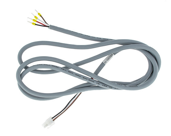
Follow Consistent Assembly Steps
Studies of electronics assembly lines show that implementing a rigid, repeatable workflow can reduce wiring errors by over 50% and increase overall production speed by 20% by eliminating corrective actions and decision pauses. For a medium-volume production run of 5,000 harnesses, standardizing the crimping and routing steps can prevent an estimated 250 field failures, saving upwards of $75,000 in warranty repairs and recalls.
Precision here is non-negotiable. For a 20 AWG wire, a strip length of 12.0mm ± 0.5mm is typical for many open-barrel terminals. An automatic stripping machine set to this length will produce 10,000 consistent strips far more reliably than manual methods, which can vary by over 2mm, leading to poor crimps. The crimping process itself must be controlled to the newton. A #20 contact might require a crimp force of 3000 N ± 200 N to form a gas-tight connection. Using a calibrated press with the correct die set, an operator should perform a pull-force test every 4 hours, verifying that the terminal withstands at least 50 N of tension without movement.
Cable ties should be applied at the locations marked on the board, tightened to a specific tension of 4-5 kg using a torque-controlled tool. Overtightening by just 1 kg can compress the insulation by 15%, potentially damaging the conductors inside.
For harnesses that will experience vibration, such as in automotive or aerospace, every 5th wire in a bundle should be secured with a friction lock tie instead of a standard nylon tie, increasing the bundle's resistance to movement by 40%. The final step is a 100% visual inspection against a checklist that specifies criteria for strip length, terminal placement, and tie-wrap orientation.
Perform Electrical Function Tests
Industry data indicates that over 60% of field failures in electrical systems are attributable to wiring and connection issues that a robust test regimen would have caught. Implementing a 100% testing protocol that includes continuity, insulation resistance, and hi-pot tests can reduce field failure rates by up to 85%. For a manufacturer building 1,000 harnesses per week, this prevention strategy avoids an estimated 15-20 field returns monthly, saving an average of $50,000 per month in warranty costs, shipping, and reputational damage.
|
Test Type |
Purpose |
Key Parameters |
Pass/Fail Criteria |
Typical Test Duration |
|---|---|---|---|---|
|
Continuity |
Verifies correct connectivity and absence of short circuits. |
Test Current: 100 mA ± 10 mA, Test Voltage: 5-10 VDC |
Resistance: < 0.1 Ω (within a circuit), > 10 MΩ (between isolated circuits) |
3-5 seconds per circuit |
|
Insulation Resistance (IR) |
Measures the quality of insulation between conductors. |
Test Voltage: 500 VDC, Ramp Time: 10 sec, Dwell Time: 60 sec |
Resistance: > 100 MΩ at 25°C, 50% RH |
~70 seconds per test group |
|
Dielectric Withstanding Voltage (Hi-Pot) |
Stresses the insulation to verify it can withstand operational overvoltage. |
Test Voltage: 1500 VAC (or 2Operating Voltage + 1000V), Time: 60 sec* |
Leakage Current: < 5 mA (no arcing or breakdown) |
60 seconds per test group |
A modern automated test system can sequence through all possible pin-to-pin combinations in a 50-pin harness in under 30 seconds. It applies a 100 mA current between point A and point B and measures the voltage drop to calculate resistance. Any reading above 0.1 Ω flags a potential issue like a poorly crimped terminal or a partially broken wire. The test must also check for shorts; the system applies the same current between every pin that should notbe connected, expecting a resistance reading exceeding 10 MΩ. A reading below 1 MΩ indicates insulation damage or a wiring error.
It applies a high DC voltage, typically 500 VDC for low-voltage systems, across the insulation barrier between conductors and from conductors to shield. The test equipment measures the resulting leakage current after a 60-second dwell time and calculates the resistance.For most applications, a minimum value of 100 MΩ is acceptable, but for harsh environments like aerospace or medical systems, the requirement can be 1 GΩ or higher. A reading of 50 MΩ might pass in a consumer device but would immediately fail a harness destined for an aircraft, where moisture intrusion is a critical risk. The hi-pot test follows, applying a high AC voltage, say 1500 VAC at 50 Hz, for one minute. The goal is not to measure resistance but to ensure the insulation does not experience dielectric breakdown. The test station monitors leakage current, and any spike exceeding 5 mA constitutes a failure. It is crucial to set the voltage correctly; applying 3000 VAC to a harness rated for 250 VAC will destroy it.
For new production, a 100% hi-pot test is performed, but for routine maintenance testing, the voltage is often reduced to 80% of the factory test value to prevent cumulative insulation stress. All test equipment must be calibrated at intervals not exceeding 6 months to ensure the applied 500 VDC is accurate to within ±5% and the leakage current measurement is precise to within ±2%.
Keep Detailed Assembly Records
The inability to trace a component failure back to a specific batch of wire or a particular operator's shift can result in a full-line recall, costing upwards of $250,000 and halting production for 5-10 days. Conversely, a digital record system that tags each harness with a unique serial number and logs every step can reduce failure investigation time by over 90%, pinpointing the root cause—such as a misconfigured crimping machine on the 3rd shift of April 15th—in minutes instead of weeks. This level of traceability directly reduces scrap rates by 15% and cuts warranty claim processing costs by 50%.
The foundation of this system is a unique identifier, such as a scannable QR code or barcode label, physically attached to the harness the moment kitting begins. This ID links the physical unit to its entire digital history in your Manufacturing Execution System (MES). The first data captured is component traceability. For each wire, the system records the manufacturer's lot number (e.g., Belden 2023-ABX-45), the spool number, and the certification of compliance (CoC) number from the supplier. This is critical: if a vendor reports a copper purity issue in lot 2023-ABX-45 six months later, you can instantly query your database and identify the 850 harnesses built with that material for proactive replacement, instead of facing a reactive crisis. During assembly, the operator logs their employee ID at the start of the process and the system records a timestamp for each major step: wire cutting completed at 10:23:45, crimping completed at 10:45:12, final routing signed off at 11:15:33. This creates an audit trail that assigns responsibility and highlights bottlenecks where a process averages 25% longer than the standard time, indicating a training need.
The 0.08 Ω continuity resistance for pin 12 to pin 45, the 525 MΩ insulation resistance measured at 502 VDC for 60 seconds, and the 2.1 mA leakage current from the hi-pot test at 1495 VAC. Storing this data for the 25-year expected life of a product provides an invaluable baseline. If a harness fails in the field, its historical test data can be compared against the 10,000 other units produced that month to identify statistical outliers. For example, if the average resistance for that circuit is 0.05 Ω ± 0.02 Ω, the failed unit's 0.08 Ω was a detectable early warning sign. These records also serve as your primary evidence for complying with ISO 9001 and AS9100 standards, which require proof of process control and data-driven corrective actions. Modern systems automatically compile this data into a Certificate of Conformance (CoC) for each shipped unit, a document that details the exact build conditions and test parameters that prove the product was built to specification and is fit for its purpose.
Ensuring quality in cable and harness assembly integrates five practices: using IPC/WHMA-A-620-compliant designs (≤0.5mm tolerance), selecting tinned copper wires (98% IACS conductivity) and IP67 connectors, following 8-10 Nm torque steps, testing continuity (<0.1Ω) and insulation (≥100MΩ), and maintaining batch-specific records. These steps reduce defects, boosting reliability.
