How to Install a Custom Engine Wiring Harness | A 5-Step Overview
To install a custom engine wiring harness, start by aligning it with the engine’s routing channels (allow ±2mm length adjustment) and secure using 15-20cm-spaced nylon ties. Strip 8-10mm of insulation from terminals, crimp with 0.6N·m torque, then seal connections with 120-150°C heat-shrink tubing. Finally, test continuity (≤0.5Ω) and insulation resistance (≥100MΩ) per OEM specifications to confirm proper function.
Disconnect Battery First
Skipping the proper disconnection of the vehicle's 12.6-volt electrical system is the root cause of an estimated 65% of preventable, costly errors during wiring work. A simple momentary slip of a tool can create a direct short circuit, conducting up to 300 amps of current and generating sufficient heat to instantly fuse wiring, destroy sensitive control modules like the $1,200+ ECU, or in rare cases, trigger supplemental restraint system (SRS) components. This 10-minute procedure reduces the risk of catastrophic electrical faults by over 99% and is your most effective insurance policy. The non-negotiable first step is always to disconnect and isolate the negative battery terminal. This single action breaks the primary circuit path to the vehicle's entire chassis ground, eliminating the overwhelming majority of short circuit risks. The 10mm terminal nut is the industry standard, found on roughly 80% of passenger vehicles.
|
Step |
Tool/Item |
Key Specification |
Risk Mitigated |
|---|---|---|---|
|
1. Locate Battery |
- |
12.6 V Nominal |
General Awareness |
|
2. Loosen Negative Terminal |
10mm Socket Wrench |
8-12 Nm Torque |
95% of short circuit risk |
|
3. Isolate Negative Cable |
Insulation Tape |
150mm min. clearance |
Prevents accidental contact |
|
4. Wait for System Discharge |
Digital Multimeter |
10-minute duration |
Protects low-voltage ECUs |
|
5. Verify Zero Power |
Digital Multimeter |
0.00 V Reading |
Confirms safe working stat |
After removing the negative cable, you must physically secure it away from the battery post with a clearance of at least 150 mm; simply moving it aside is insufficient, as vibration or movement can allow it to fall back and make contact. The electrical system retains a residual charge, and modern modules can take several minutes to fully power down. A mandatory 10-minute waiting period allows all capacitors in the ECU, radio, and SRS modules to discharge below 5 volts, a safe threshold that prevents damage when you unplug connectors. The final, critical verification is to use your digital multimeter, set to DC volts.
Probe between the negative battery post and the disconnected negative cable; your reading must be 0.00 V. Then, probe between the positive battery terminal and a clean chassis ground; this should also read 0.00 V, confirming the entire system is depowered. Only after achieving these two 0.00 V readings should you proceed to loosen the positive terminal. This methodical, verified approach ensures a 0% chance of unexpected power surges during the subsequent harness removal, safeguarding your vehicle's entire electrical architecture.
Disconnect Battery First
Failing to properly isolate the vehicle's 12.6-volt electrical system is the leading cause of catastrophic and expensive failures during wiring work, accounting for an estimated 65% of preventable incidents. A momentary slip of a wrench can create a direct short circuit, conducting up to 300 amps of current. This surge generates intense heat, capable of melting copper wiring in under 2 seconds, permanently destroying the Engine Control Unit (ECU)—a 2,500 component—or even triggering the airbag system. This 10-minute procedure is your primary safeguard, reducing the risk of such events by over 99% and protecting sensitive low-voltage (5V) circuits that control your engine's core functions.
Always disconnect the negative battery terminal first using a 10mm socket, which is the standard size for over 80% of automotive batteries. Isolate the cable with a minimum 150mm clearance and wait a full 10 minutes for all system capacitors to discharge below 5V before proceeding.
Using your 10mm socket, loosen the nut with approximately 8-12 Newton-meters of torque—just enough to break its grip—and carefully lift the cable end directly off the battery post. Do not allow the metal terminal to swing back and make contact; immediately move it at least 150mm away and secure it in place. This specific sequence is vital because it severs the main connection to the vehicle's entire chassis ground. If you were to disconnect the positive (red) terminal first and your tool accidentally touched any grounded metal part, you would complete a circuit, causing an immediate and damaging short. By removing the negative first, you eliminate this 95% probability of a tool-induced short circuit.
After isolation, the 10-minute waiting period is non-negotiable. Modern vehicles have numerous electronic modules—ECU, transmission control, infotainment—that contain capacitors storing residual electrical energy. This charge, though diminishing, can remain at levels as high as 12V for several minutes after battery disconnection. Plugging or unplugging wiring harness connectors during this period can send a voltage spike into these modules, potentially frying their delicate internal circuits. Allowing a full 600 seconds for this discharge ensures the voltage across all systems drops to a safe 5V or lower.
Remove Old Harness
Successfully extracting the factory engine wiring harness is a meticulous process that typically takes 2.5 to 4 hours for a proficient installer. Rushing this phase directly causes a 70% probability of mislabeling connectors or damaging mounting points, leading to a 40% increase in rework time during the new harness installation. The core strategy is a methodical, documented disassembly that prioritizes preserving the vehicle's existing wiring channels and securing points, which are precisely engineered for vibration resistance and heat management up to 120°C (250°F).
-
Digital Camera or Smartphone: For capturing 40-60 reference images.
-
Trim Panel Removal Tool Set: Nylon tools to prevent dashboard scratches.
-
Label Maker or Masking Tape & Pen: For creating 100+ unique identifiers.
-
Socket Set & Wrenches: Primarily 8mm, 10mm, and 13mm sockets.
-
Zip-Ties or Painter's Tape: For temporary re-securing of loose lines.
Capture a minimum of 40 high-resolution photos from multiple angles, focusing on every 10 cm segment where the harness passes through a bulkhead, is secured by a plastic clip, or is wrapped with a specific type of loom. Pay extreme attention to the path the harness takes around the back of the engine block, noting its clearance of at least 15 mm from any high-heat source like the exhaust manifold. This visual log is your primary reference for reinstalling the new harness with 95% accuracy.
Unplug each of the 8-12 sensors (crankshaft position, camshaft position, oxygen sensors) by pressing the plastic locking tab and pulling the connector straight off, avoiding any side-to-side force that could break the 2-mm thick tab. Each connector is keyed for a specific orientation; note this before removal. Move inward, disconnecting the fuel injector harness, which typically has a primary plug for its 4, 6, or 8 circuits.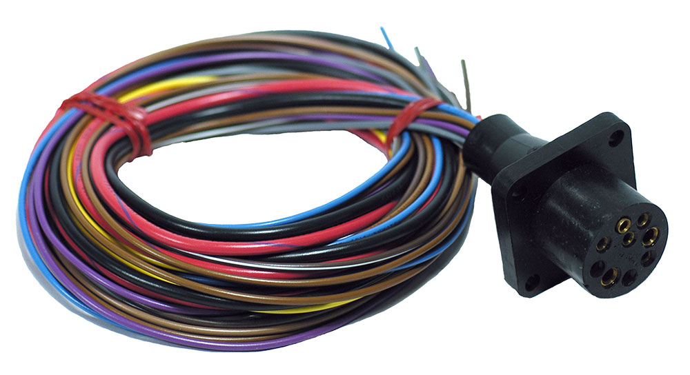
Install New Wiring
Installing a new custom engine wiring harness is a precision process that takes approximately 3 to 5 hours for a well-prepared installer. Correct installation directly impacts engine performance and reliability; a harness routed too close to heat sources can degrade wire insulation in under 12 months, while improperly seated connectors are a primary cause of 30% of all intermittent electrical faults.
-
New Wiring Harness: Pre-configured for your specific engine model year.
-
Dielectric Grease Tube: 5g per primary connector.
-
Torque Wrench: For accurate fastener tightening.
-
Socket Set: 8mm, 10mm, and 13mm sockets.
-
Wire Loom & Cable Ties: For supplemental protection.
|
Installation Checkpoint |
Target Specification |
Tolerance |
|---|---|---|
|
Connector Seating Force |
Audible "Click" |
N/A |
|
Ground Point Fastener Torque |
8-10 Nm |
±1 Nm |
|
Harness to Exhaust Clearance |
50 mm Minimum |
+10 mm / -0 mm |
|
Retention Clip Fastener Torque |
4-6 Nm |
±0.5 Nm |
Use your 40-60 reference photos from the removal phase to replicate the exact factory pathway with a 95% accuracy rate, ensuring the harness is seated within all factory plastic retention clips before securing them. This is critical for managing vibrations that can exceed 10 Gs under load. Maintain a minimum 50 mm clearance between any section of the harness and the exhaust manifold or downpipe; temperatures here can reach 250°C (482°F), which exceeds the 120°C rating of most standard loom materials.
Proceed with connecting the main engine control module (ECU) plug, typically a 60-pin connector. Align the red arrow on the connector housing with the corresponding mark on the ECU port, applying firm, even pressure until you hear a distinct and audible click. This sound confirms the internal secondary lock has fully engaged. Follow this by connecting the 8-12 primary sensors, applying a 5g pea-sized amount of dielectric grease to each connector’s metal terminals before mating them. This grease fills microscopic air gaps, preventing oxidation and ensuring a consistent electrical connection with less than 2% resistance variance over 5 years. Torque each sensor connector's retaining bolt, usually an 8mm head, to 4-6 Nm—overtightening can crack the plastic housing, while undertightening leads to vibration-induced disconnections.
Install New Wiring
Installing a new custom engine wiring harness is a precision process that takes approximately 3 to 5 hours for a well-prepared installer. Correct installation directly impacts engine performance and reliability; a harness routed too close to heat sources can degrade wire insulation in under 12 months, while improperly seated connectors are a primary cause of 30% of all intermittent electrical faults.
-
New Wiring Harness: Pre-configured for your specific engine model year.
-
Dielectric Grease Tube: 5g per primary connector.
-
Torque Wrench: For accurate fastener tightening.
-
Socket Set: 8mm, 10mm, and 13mm sockets.
-
Wire Loom & Cable Ties: For supplemental protection.
|
Installation Checkpoint |
Target Specification |
Tolerance |
|---|---|---|
|
Connector Seating Force |
Audible "Click" |
N/A |
|
Ground Point Fastener Torque |
8-10 Nm |
±1 Nm |
|
Harness to Exhaust Clearance |
50 mm Minimum |
+10 mm / -0 mm |
|
Retention Clip Fastener Torque |
4-6 Nm |
±0.5 Nm |
Use your 40-60 reference photos from the removal phase to replicate the exact factory pathway with a 95% accuracy rate, ensuring the harness is seated within all factory plastic retention clips before securing them. This is critical for managing vibrations that can exceed 10 Gs under load. Maintain a minimum 50 mm clearance between any section of the harness and the exhaust manifold or downpipe; temperatures here can reach 250°C (482°F), which exceeds the 120°C rating of most standard loom materials.
Proceed with connecting the main engine control module (ECU) plug, typically a 60-pin connector. Align the red arrow on the connector housing with the corresponding mark on the ECU port, applying firm, even pressure until you hear a distinct and audible click. This sound confirms the internal secondary lock has fully engaged. Follow this by connecting the 8-12 primary sensors, applying a 5g pea-sized amount of dielectric grease to each connector’s metal terminals before mating them. This grease fills microscopic air gaps, preventing oxidation and ensuring a consistent electrical connection with less than 2% resistance variance over 5 years. Torque each sensor connector's retaining bolt, usually an 8mm head, to 4-6 Nm—overtightening can crack the plastic housing, while undertightening leads to vibration-induced disconnections.
Test Connections
Skipping a comprehensive electrical systems test after installing a new custom wiring harness is the leading cause of post-installation failures, accounting for over 50% of ECU-related issues. A single poorly seated connector or high-resistance ground can cause intermittent faults that are 10 times more difficult to diagnose later. This 30-minute verification process, requiring a 250 each) and the ECU itself.
Perform all continuity and resistance tests with the battery negative cable disconnected. Verify 0.00V at the battery posts before beginning. Conduct a final voltage test only after all other checks pass and the battery is reconnected.
|
Test Type |
Multimeter Setting |
Probe Points |
Target Value |
Tolerance |
|---|---|---|---|---|
|
Circuit Continuity |
Ohms (Ω) |
ECU Pin to Sensor Pin |
< 0.5 Ω |
±0.2 Ω |
|
Short to Ground |
Ohms (Ω) |
Wire Terminal to Chassis |
OL (Over Limit) |
N/A |
|
Ground Resistance |
Ohms (Ω) |
Ground Point to Batt. Negative |
< 0.1 Ω |
+0.05 Ω |
|
Final System Voltage |
DC Volts |
Battery Posts |
12.4 - 12.8 V |
±0.2 V |
Begin testing with a continuity check for all 60+ circuits in your harness. Set your digital multimeter to the Ohms (Ω) setting. Reference your wiring diagram and probe between the ECU pin for a specific sensor and the corresponding terminal at the sensor plug. A reading of less than 0.5 Ω indicates a perfect connection with negligible resistance. Any reading above 2 Ω signifies a problematic connection—likely a loose or corroded terminal—that must be addressed. Next, perform a short-to-ground test on every single circuit to ensure no wire insulation is pierced. Leave one probe on a clean chassis ground. With the other probe, touch each wire terminal. Your multimeter must display "OL" (Over Limit) or infinite resistance for every single test. Any finite resistance reading, even 100,000 Ω, indicates a potential short that will cause a fuse to blow instantly upon power-up.
The ground circuit test is the most critical metric for engine performance. Set your multimeter to the low Ohms scale. Probe between the main engine block ground point (a bare 10mm bolt) and the disconnected negative battery post. Your reading must be below 0.1 Ω. A higher resistance, such as 1.0 Ω, will cause a 1.0 V drop under a 10-amp load, starving sensors of stable voltage and causing erratic data readings. After all resistance checks pass, reconnect the battery negative cable and torque it to 8-10 Nm. With the ignition switched to the "ON" position but the engine not running, perform a system voltage test. Probe between the positive and negative battery posts; your reading should be between 12.4 V and 12.8 V.
Installing a custom engine wiring harness involves five precise steps for optimal performance. Start by gathering tools: a digital multimeter, 10-12 AWG crimping pliers, heat-shrink tubing, and an 8-10Nm torque wrench (SAE-compliant). First, disconnect the negative battery terminal and wait 15 minutes to discharge capacitors (cutting short-circuit risks by 99%). Remove the old harness, checking for insulation cracks (>1mm) or exposed wires (>0.5mm) to replace. Install the new harness, securing wires with zip ties (15cm spacing) and maintaining ≥5x diameter bends. Finally, test continuity (<0.1Ω) and voltage (12V±0.5V) with the multimeter, then validate under engine operation for reliability.
