How to Select Molex Wire Harness Connectors
To select Molex wire harness connectors, prioritize application needs: for automotive, opt for 10A/250V-rated, 8-24 pin models (e.g., 39390 series) with IP67 sealing. Use Molex’s online selector, verifying -40°C to +125°C temp range and >500 mating cycles for durability.
Define Electrical Requirements
When selecting connectors, electrical parameters are the foundation. If the foundation is not solid, all subsequent designs may be in vain. Don't underestimate a small terminal; choosing the wrong one can lead to anything from unstable signals and device reboots, to connector overheating, melting, and even causing a fire.
For example, the common Molex KK series (2.54mm pitch) typically has a current rating of only 3A per terminal. If you naively use it to power a device with a peak power of 60W at 12V, it will likely be the weakest link in your system.
Current
When selecting a connector, current is the first parameter to nail down. It's like planning lanes for a road: if you expect 100 cars per day but actually get 1000, traffic jams and breakdowns are inevitable. Choosing an undersized connector can lead to excessive temperature rise causing device resets, or worse, terminal overheating and oxidation, leading to a surge in contact resistance, creating a vicious cycle that ends with the connector melting and the entire system failing.
Don't underestimate the small connector; it is the current choke point of the entire system. A connector rated for 5A at 25°C room temperature might only safely carry 3.5A inside a 60°C equipment chassis.
How to interpret the current value on the datasheet
When you get a Molex datasheet, don't just look at the large "Rated Current" number on the first page. That value is usually measured under specific test standards (like UL/CSA) in a lab environment of 20-25°C.
For example, Molex's classic Mini-Fit Jr. series has a per-pin rated current of 9A at 25°C. But when the ambient temperature rises to 50°C, its current-carrying capacity drops to about 8A; at 80°C, it might be only 6.5A. If your device interior consistently operates at 70°C, but you design the circuit for 9A, the risk is very high. Industry practice typically requires a 20%-30% margin. That means, for a desired continuous current of 6A in a 70°C environment, you should ideally choose a connector model that can carry at least 7.5A or more at 70°C.
Terminal material and plating directly determine "transmission line loss"
Connector terminals are typically made from phosphor bronze or beryllium copper as the base material due to their good conductivity and elasticity. But more importantly, the surface plating is critical.
-
Pure Tin Plating: Low cost, but prone to surface oxidation over time, leading to a gradual increase in contact resistance. Suitable for consumer electronics with an expected lifespan of 3-5 years.
-
Gold Plating: Chemically stable, with low and extremely stable contact resistance. But gold is expensive, so it's usually plated very thinly, e.g., 0.76µm (30 microinches). High-reliability industrial, medical, and automotive electronics (e.g., airbag circuits) must use gold plating, even if it costs 2-3 times more than tin-plated terminals.
Contact resistance is the core hidden metric. A high-quality connector terminal should have a contact resistance controlled below 20 milliohms. Don't underestimate this number. When passing a 5A current, the power loss on a single terminal is P = I²R = 5² * 0.02 = 0.5W. If a connector has 10 powered pins, the total loss is 5W. These 5 watts of heat are concentrated within the small connector volume.
Wire gauge and terminal matching is fundamental
The metal structure of a terminal is optimized for a specific wire gauge (AWG). For example, a terminal in Molex's Micro-Fit 3.0 series is designed to crimp AWG 22-24 wires (cross-section ~0.2-0.3mm²). If you force a thicker AWG 18 wire (cross-section ~0.8mm²) into it, not only will it not crimp properly, but it might damage the terminal's crimp barrel. Conversely, using a large terminal for a thin wire results in insufficient contact area and a significant increase in contact resistance.
Simply put, a connector rated for 5A must be paired with a wire that can also handle 5A. Typically, AWG 22 wire for chassis wiring has a safe ampacity of about 3-5A, which matches the rating of many small connectors. If the current reaches 10A, you might need to choose a connector like Mini-Fit Jr. and pair it with AWG 16 or thicker wire.
Difference between instantaneous peak current and steady-state current
Some devices, like motors and incandescent lamps, can have inrush currents at startup that are 5-10 times their steady-state operating current. Although this peak is very short (tens to hundreds of milliseconds), it significantly stresses the connector terminals.
The key value for a terminal passing current is the thermal effect (I²t). For connectors capable of withstanding short-term overcurrent, their datasheet might provide a "Current vs. Time" curve. For example, a terminal might be specified to withstand 20A for no more than 10 seconds. This means it can handle a brief startup surge. If your motor's inrush current is 15A (for 1 second) and the steady-state current is 3A, then selecting a connector rated for 5A with short-term overload capability is feasible. But if the peak current reaches 30A, you must consider a series with a higher current rating.
Voltage
A connector rated for 250V might see its actual breakdown voltage plummet below 150V in an environment with 85% humidity. DC high-voltage systems are the most dangerous – for example, photovoltaic string voltages can reach 1000V DC. Once an arc is established, it won't extinguish at a zero-crossing like AC, and will continue to burn until the entire connector is destroyed.
Working voltage and withstand voltage are two different things
Many people see their system voltage is 24V DC, choose a connector rated for 250V AC, and think it's more than enough. This is a fatal mistake. 250V AC refers to the RMS value; its peak voltage is as high as 250×1.414≈350V. Furthermore, AC is less prone to sustaining an arc than DC. Even though your 24V DC system voltage is low, if the circuit connects to a large inductor (like a relay or motor), the induced voltage spike when disconnected can easily exceed 500V. This transient high voltage is enough to break down the insulation. Therefore, when selecting a connector, its rated voltage must be greater than the maximum peak voltage that might occur in the system, with sufficient margin. Industry typically requires a safety factor of 1.5 to 2.
Creepage and clearance are the lifelines for high voltage
-
Clearance: The shortest distance through air between two conductive terminals. The dielectric strength of dry air is about 3000V/mm, but it is greatly affected by humidity and pollution. IEC standards require, for a 250V RMS working voltage, a minimum clearance for basic insulation is typically specified as 1.5mm.
-
Creepage: The shortest path along the surface of the insulating material between two conductive terminals. This distance must consider the material's CTI (Comparative Tracking Index). If the surface is contaminated with dust and moisture, even at low voltages, a leakage path can form. For the same 250V RMS, using a CTI Level III material (common for PBT plastic), the required creepage distance might be as high as 2.5mm.
For high-voltage applications, like the 400V/800V battery systems in electric vehicles, the creepage and clearance requirements inside the connector increase dramatically. They might need to reach 8mm or even 15mm or more, which directly results in very large connector sizes and prices that are ten times or more that of ordinary connectors.
Insulating material determines the voltage withstand ceiling
-
Standard Materials: Like PA66 (Nylon 66), which has good mechanical strength but average moisture resistance and CTI value. Its insulation performance degrades under long-term high temperature and humidity, making it suitable for low-voltage consumer electronics.
-
High-Performance Materials: Materials like PBT, PPS have higher CTI values (e.g., PPS CTI can be over 250V) and better heat resistance (RTI can reach 120-140°C), making them the preferred choice for industrial and automotive grade connectors. The price of materials can differ by several times, which is why an industrial connector with the same pin count is much more expensive than a consumer-grade one.
DC high voltage tests connectors more harshly
DC systems lack a zero-crossing point. Once an arc is established, it is harder to extinguish than an AC arc. This is especially true during live plugging (hot-swapping), where an arc is inevitably drawn the moment the contacts separate. Therefore, high-voltage DC connectors (like HVDC) must have specialized arc extinguishing designs, such as using magnetic materials to stretch the arc for rapid extinguishing, or employing complex structures like pilot and ground contacts. Ordinary AC connectors are absolutely forbidden in high-voltage DC environments; this is a rule written in blood.
The effect of altitude is often overlooked
As altitude increases, air density decreases, reducing the dielectric strength of air. IEC standards stipulate that for every 1000 meters increase in altitude, the withstand voltage needs to be derated by about 10%. If your equipment is used on a plateau at 2000 meters altitude, a gap rated for 3000V might only withstand about 2400V in reality.
Signal Type
For a circuit powering a 5V/1A sensor, the connector just needs reliable contact. But when transmitting a PCIe 4.0 signal (up to 16 GT/s per lane), the connector's own characteristics become the system bottleneck. We have measured that using a standard pin header to transmit signals over 1GHz causes the signal edge to collapse from a sharp 0.7 nanoseconds to over 2 nanoseconds, the eye diagram completely closes, and the bit error rate deteriorates from 10⁻¹² to unusable.
The difference between low-speed switching signals and power transmission
-
What matters for Power Transmission: The core metrics are current-carrying capacity (Amperes) and contact resistance (typically required < 20mΩ). As long as the connector doesn't overheat and the voltage drop is within limits, the job is done. For example, using a Molex Mini-Fit Jr. connector to transmit 12V/10A power, you only need to focus on the terminal material thickness and crimp quality.
-
What matters for Low-Speed Signals: Like a switch signal toggling 100 times per second, or serial ports like RS-232/RS-485 with baud rates up to 115200. The frequencies are very low (typically below 1MHz), and the connector's parasitic parameters (capacitance, inductance) have minimal impact.
The real watershed appears when signal frequency exceeds 1MHz, especially rising above 10MHz. At this point, the connector is no longer an ideal conductor but a complex "RF component".
Why high-speed signals are a different dimensional problem
When signal changes become fast enough (rise/fall times as short as nanoseconds or even picoseconds), every millimeter of conductor inside the connector generates parasitic inductance and capacitance. These parasitic parameters interact with the signal frequency itself, producing three fatal effects:
-
Impedance Discontinuity and Signal Reflection: High-speed digital signals (like USB, HDMI, SATA) require a constant characteristic impedance (typically 50Ω single-ended or 100Ω differential) throughout the entire transmission path. If the impedance in the connector region is uncontrolled (e.g., becomes 70Ω or 40Ω), signal energy reflects at the impedance discontinuity point. Reflected signals superimpose on the original signal, causing overshoot, undershoot, and ringing, potentially leading to logic level misinterpretation. A connector with poor impedance control can cause over 15% of the signal energy to be reflected back.
-
Insertion Loss: As a signal passes through the connector, its energy is attenuated due to conductor loss and dielectric loss. This loss increases sharply with frequency. For example, a connector used for PCIe 3.0 might be required to have an insertion loss less than -1.5dB at 4GHz. If the loss is too high, the signal amplitude at the receiver is insufficient for correct identification.
-
Crosstalk: When multiple high-speed lines run side-by-side through a connector, energy from one signal line can couple into an adjacent quiet signal line, creating noise. The dense pin arrangement inside connectors is a hotspot for crosstalk. The datasheet will provide parameters for near-end and far-end crosstalk; a good high-speed connector should have crosstalk better than -40dB at 10GHz.
How specialized high-speed connectors solve these problems
-
Coaxial Connectors: This is the classic solution. It uses a central signal pin surrounded by a complete metal shield, separated by a dielectric material, forming a precisely controlled 50Ω impedance. This method completely "protects" the signal, making it almost immune to external interference and preventing energy leakage. The drawback is that it typically only transmits single-ended signals and is more expensive.
-
Differential Pair Connectors: This is the mainstream for current high-speed digital buses (like USB, Ethernet, DisplayPort). It uses a pair of tightly coupled signal lines (D+ and D-) to transmit the signal. External noise affects both lines equally (common-mode), which is rejected by the differential amplifier at the receiver. The key to such connectors is ensuring the two lines are strictly equal in length (phase difference less than 5 mils) and have stable spacing to achieve a precise 100Ω differential impedance. Series like Molex's Edge-Line DP are specifically designed for this.
-
Shielded Pin Headers/Receptacles: Based on the traditional pin header structure, a metal shield is added or ground pins are inserted between signal pins, providing a nearby return path for each high-speed signal and suppressing crosstalk. For example, placing 1 ground pin after every 4 signal pins is a common "G-S-S-S-S-G" pattern.
During selection, you must compare the fastest rise time and highest frequency component of your signal (typically 0.35 / rise time) against the connector's S-parameter curves (Scattering parameters), especially insertion loss and return loss. If the connector's -3dB bandwidth is lower than the highest effective frequency of your signal, waveform distortion is inevitable. For example, to transmit a square wave with a 100ps rise time losslessly, its effective frequency components reach up to 3.5GHz, requiring a connector bandwidth of at least 5GHz or more.
Determining Circuit Scale and Pitch
A 10-pin connector, if mistakenly chosen with a 2.54mm pitch, might be twice the size of a solution using a 1.27mm pitch, directly occupying a precious 200mm² area on the PCB. Conversely, a motor circuit needing to carry 5A current, if incorrectly crammed into a connector with a pitch of only 1.0mm, could cause the terminal to overheat, contact resistance to surge by 50%, or even lead to failure. The core idea is that you need to safely and economically accommodate all circuit signals and power within a limited physical space.
Number of Signals
Over 60% of hardware rework stems from exhausting connector pin resources. When you find you need an extra 3.3V supply to debug a sensor, but all pins are occupied, you either have to fly wires (violating production standards) or bear the cost of a PCB revision taking 2 weeks and costing over $5000.
What are the signal types? Their handling differs completely.
-
Power/Power Signals: These are the "big consumers". A 5V supply for a motor driver board might only need 1 pin, but it has to carry 2A of continuous current. This means you must assign it a sufficiently thick terminal, sometimes even needing 2 or more pins in parallel to share the current and reduce impedance. Conversely, a 3.3V LDO input providing a reference for a chip, drawing only 50mA, might occupy just 1 standard pin.
-
Ground Signals: Ground is the return path for current; you can never have too many. A common mistake is providing only 1 common ground pin for both digital and analog circuits, which leads to noise coupling, causing ADC readings to jump by ±5 LSB or more. Best practice is to use at least 2 separate pins for digital ground (DGND) and analog ground (AGND) at the connector, eventually connecting them at a single star point in the system.
-
Digital Signals: Including GPIO, UART, I2C, SPI, etc. They are the mainstay in terms of quantity. I2C only needs 2 pins (SDA, SCL) but can connect multiple devices. Standard SPI requires 4 pins (CS, SCLK, MOSI, MISO), and each slave device requires a dedicated 1 Chip Select (CS) pin. A system needing to connect 3 SPI slaves uses 4 + 3 = 7 pins just for the SPI bus.
-
Analog Signals: Like sensor voltages read by an ADC. They are extremely fragile and noise-sensitive. When laying out the connector, analog signal pins must be kept at least 2-3 pin positions away from any fast-switching digital signals (like PWM, clocks), preferably with ground pins in between for isolation. Otherwise, the readings will be full of noise.
-
High-Speed Differential Signals: Like USB 2.0 (1 differential pair), MIPI DSI (4 differential pairs). They are the "aristocrats", must appear in pairs, and have stringent requirements for length matching and impedance control between the pins.
How many pins to reserve is considered "smart reservation"?
"Reserve 10%-20%" is a guideline, but the specific number depends on the product stage and type.
-
R&D Prototype Stage: Uncertainty is highest here. It's recommended to reserve 25% - 30% redundant pins. For example, if core functions need 40 pins, choose a 50-position or 54-position connector.
-
Mass-Production Mature Product: Cost becomes extremely sensitive. Reserved space can be greatly reduced, but it is strongly advised not to reduce it to zero. Keeping 5% of pins (e.g., reserving 2 pins in a 42-pin design) is a safe bottom line.
-
The "Hidden" Cost of Reserved Pins: Each additional pin means one more copper strand in the cable, one more action for the crimping machine; the cost accumulates. If a connector costs $0.10 per pin, a mass-produced item with 10 extra redundant pins shipping 1 million units would see a total cost increase of $0.10 * 10 * 1,000,000 = $100,000.
Don't forget test points and debug interfaces
-
Programming Interface: Like JTAG/SWD, typically requiring 4-5 pins (TCK, TMS, TDI, TDO, RESET). These pins might be useless after the product leaves the factory, but are essential for R&D and production programming. You must decide whether to assign a dedicated connector (possibly used only in production) or share pins with the main functional connector.
-
System Status Monitoring: Reserve 1 pin connected to the main chip's GPIO to drive an indicator showing "System Powered", "Fault Code" (using different blink patterns). This greatly reduces after-sales repair difficulty and time.
-
Critical Voltage Measurement Points: Bring out signals like the Power Good signal from the PMIC or the chip core voltage, allowing direct probing with an oscilloscope during debug without searching for test points on a dense PCB.
Physical Space Constraints
A connector that is just 1.5 millimeters taller can prevent the product enclosure from closing, stalling the entire project. Inside a smartphone pursuing 82% screen-to-body ratio, the average height of connectors is compressed to under 2 millimeters. On a dense backplane of an industrial PLC module, over 200 connectors might share limited board edge space, with gaps between adjacent connectors possibly only 0.8 millimeters, requiring specially designed insertion/extraction tools. Ignoring spatial constraints during selection is equivalent to planting a time bomb during the design phase.
First, measure your own "territory" accurately
Before browsing catalogs, the first step is to pick up calipers and precisely measure the "slot" reserved for the connector on the PCB and within the enclosure. Tolerance must be controlled within 0.2 millimeters.
-
Length and Width are the planar basis: Measure the installation area the connector occupies on the PCB. The key is to confirm if extra "clearance space" is needed beyond the connector body for the locking clip's spring arm, or the bend radius of the cable exit. A connector body 30 mm long might have a lock that protrudes 2 mm backwards, and the cable exit might need a 5 mm unobstructed area in front.
-
Height is the critical vertical dimension: This is the most easily overlooked dimension. You need to measure the clearance height from the PCB solder pad surface to the inner wall of the chassis. This height must be greater than the sum of the connector body height, the bulge height after cable insertion, and any potential manufacturing tolerances. For example, with a clearance of 6 mm, a connector body height of 4.5 mm, and a cable bundle bulge of about 1.2 mm above the housing after insertion, the remaining space is only 0.3 mm.
-
Don't forget the interference matrix: Draw a simple 2D sketch marking all tall components within 5 mm of the target connector, like electrolytic capacitors, heat sinks, inductors. Ensure there are no obstacles in the path of the connector during insertion/removal. A 4 mm tall inductor placed too close might prevent a technician's fingers or an automated tool's gripper from pressing the lock release.
Quick estimation formula for connector size
When you have a target pin count and candidate pitches, you can quickly estimate the approximate length of the connector to avoid models that are obviously unsuitable from the start.
-
Single-row connector approximate length ≈ (Number of Pins - 1) × Pitch + Fixed Ear Width
-
For example, a 20-position, 2.54 mm pitch single-row connector length ≈ (20-1) × 2.54mm + approx. 3mm ≈ 51.26 mm. If your available board edge length is only 48 mm, this model is immediately ruled out.
-
-
Dual-row connector length ≈ (Pins per Row - 1) × Pitch + Fixed Ear Width
-
The length of a dual-row connector is determined by the number of pins per row, not the number of rows. A 2x10 (total 20-pin) dual-row connector with a 2.00 mm pitch has a length ≈ (10-1) × 2.00mm + approx. 3mm ≈ 21 mm. Compared to a single-row of the same pin count, the length is saved by over 50%.
-
What to do when space is truly insufficient
Ideal space is always lacking. Here are some strategies to "squeeze" space.
-
Strategy 1: Switch to Vertical/Right-Angle Connectors: When horizontal board edge space is insufficient but vertical space is available, choose connectors with 90-degree bent pins (vertical or right-angle). They don't occupy board edge length but extend upwards or downwards, moving the mating interface to the top or bottom of the board. This can typically reduce the footprint area by 30% to 60%.
-
Strategy 2: Use Stacked or Mezzanine Connectors: In extremely compact board-to-board connections, use stacked connectors like Mezzanine types, which allow two PCBs to be stacked parallel like a sandwich, with spacing as small as 3 mm, utilizing the Z-axis space.
-
Strategy 3: Choose a "Thinner" Housing: Compare the width of housings from different manufacturers for the same pitch. Some housings have thinner walls and more compact cable latch designs. A slight optimization, say from 4.2 mm width to 3.8 mm, saves 0.4mm * 19 ≈ 7.6 mm of precious length on a 20-position connector.
-
Strategy 4: Accept Side-Exit or Rear-Exit Cable Design: If front-exit cables would block critical components, choose models where the cable exits from the side or the rear (parallel to the PCB). This changes the cable routing path but can resolve space conflicts.
Leave operational space for production and maintenance
The connector's life isn't over once soldered onto the PCB; you must consider operability throughout its lifecycle.
-
Automated Assembly: If using SMT process, the connector body shouldn't be too tall or unstable, otherwise it might tilt on molten solder paste during reflow due to its own weight, causing "tombstoning". Manual Insertion/Extraction Space: Technicians need to be able to use fingers or tools. Thumb and finger operation requires at least 15 mm x 15 mm of free operating area. For connectors with lever locks, check the rotation radius required when the lever is lifted; this arc space must be clear of any obstructions.
-
Cable Bend Radius: After the cable is connected, ensure a minimum bend radius of 5 times the cable diameter to avoid sharp bends breaking internal copper strands.
Strong Correlation Between Current Size and Pitch
Routing a power line that needs to carry 5A on a connector with a pitch of only 1.0mm is as risky as working on a high-voltage line. At an 85°C ambient temperature, a 2.54mm pitch terminal rated for 3A might see its actual safe current carrying capacity drop sharply to below 1.8A, a decrease of up to 40%.
The creepage distance between contacts directly determines the maximum withstand voltage. For example, a 150V AC working voltage typically requires a pitch no less than 1.5mm. The physical size of the terminal – directly limited by the pitch – determines resistance and heat generation. A terminal with a cross-sectional area of 0.2mm² compared to one of 0.5mm², when passing 3A current, could have a temperature rise difference of over 20°C.
Don't think of pitch merely as a distance issue
-
Withstand Voltage and Creepage Distance: These are hard requirements from safety standards (like UL, IEC). Between two adjacent live conductors, air is an insulator, but if the electric field strength is too high, breakdown occurs, creating an arc. Creepage distance is the shortest path along the insulating material surface; it must be long enough to prevent leakage under humid, contaminated conditions. For instance, for 250V AC mains input, basic insulation typically requires 3.2mm creepage and 3.2mm clearance.
-
Terminal Size and Resistance: Pitch physically limits the maximum size of the terminal. A connector with a 0.64mm pitch might have a terminal width of only 0.3mm, thickness 0.2mm, and cross-sectional area about 0.06mm². Based on metal resistivity, its resistance per unit length will be much higher than a terminal in a 2.54mm pitch connector which might have an area of 0.5mm². By Joule's Law (P = I²R), with 3A current, the heat generated by the small terminal could be 8 times or more than the large one, leading to uncontrolled temperature rise.
-
Heat Dissipation Capability: Large pitch means thicker plastic insulation (housing) between adjacent terminals, providing thermal isolation. Also, more space allows better air flow for heat dissipation.
Current/Voltage capability quick reference for different pitches (Typical values)
|
Pitch Category |
Typical Pitch Value (mm) |
Single Pin Typical Current Range (A) |
Typical Withstand Voltage Range (V AC) |
Most Common Application Scenarios |
|---|---|---|---|---|
|
Ultra-Fine Pitch |
0.4, 0.5, 0.64 |
0.5 - 1.0 |
50 - 100 |
Smartphone internals, wearables, high-speed diff signals |
|
Fine Pitch |
0.8, 1.0, 1.27 |
1.0 - 3.0 |
150 - 500 |
Consumer mainboards, industrial control modules, network interface cards |
|
Standard Pitch |
2.0, 2.54, 2.50 |
3.0 - 7.0 |
250 - 1000 |
General board-to-wire, appliance control boards, LED drivers |
|
High-Power Pitch |
3.96, 5.08, 7.62 |
7.0 - 25+ |
1000 - 5000 |
Power distribution units, industrial motor drives, new energy equipment |
Derating curve is the lifeline in high-current scenarios
-
What is Derating? The current carrying capacity of almost all connectors must be reduced as the ambient temperature increases. This is defined by a derating curve. For example, a terminal rated for 5A at 20°C might require its maximum allowed current to be reduced to 3A when the ambient temperature reaches 85°C. If you ignore this curve and still pass 5A at 85°C, the terminal's actual temperature might exceed the plastic softening point of 125°C, causing housing deformation, loss of contact force, and potentially severe overheating and fire risk.
-
How to find the derating curve: In datasheets from brands like Molex, there will always be a chart with X-axis as ambient temperature (e.g., from -40°C to +105°C) and Y-axis as percentage of current (%). You need to find the corresponding derating factor based on the worst-case ambient temperature inside your product (e.g., 75°C inside a car dashboard in summer). Never ignore derating when estimating current.
How to layout when power and signals are mixed together
-
Zoning: Physically separate power pins (e.g., 12V_IN, GND_PWR) and signal pins (e.g., SDA, ADC_SENSOR), concentrating them at opposite ends of the connector or on different rows. Avoid placing high-current power pins adjacent to weak analog signal pins; ground bounce noise from the former's switching can directly couple into the latter, rendering analog readings useless.
-
Use Ground Pins as "Barriers": Place several ground pins between the power zone and the signal zone as shielding and noise discharge paths. This is like building a soundproof wall between a noisy workshop and a quiet office.
-
Use Dedicated Power Pins: Many connector series offer "mixed" or "high-current" terminals. For example, within a 2.54mm pitch connector housing, most positions hold standard signal terminals, but 2-4 specified positions can accept larger, power-dedicated terminals.
When the current is truly too high for one pin to handle
-
Multiple Pins in Parallel: This is the most common method. Distribute a high-current path across 2, 3, or even 4 parallel terminals. For example, each terminal rated for 7A, 3 in parallel could theoretically handle 21A. But the key point here is: ensure the impedance of these parallel paths – from PCB trace to terminal crimp – is as equal as possible. Otherwise, current will predominantly take the path of least resistance, overloading that terminal while others don't share the load effectively.
-
Choose a Dedicated High-Current Connector: When current exceeds 20A or voltage exceeds 600V, directly select connector series specifically designed for high-power applications, like Molex's Mega-Fit series.
Environmental and Material Requirements
A connector costing a few dollars, if made from temperature-sensitive material, can soften and deform in a 70°C chassis, leading to poor contact, module failure, and a repair cost exceeding $500. Or, in humid southern climates, metal pins can corrode and rust in less than three months, causing the signal error rate to soar by 30%.
Environmental and material requirements are not theoretical; they directly determine whether the product's Mean Time Between Failures (MTBF) can meet the designed 10,000 hours or more in the real world, and whether it can withstand harsh tests like 85°C/85%RH (double 85 test).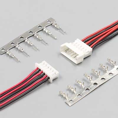
Temperature
In the severe cold of -40°C, ordinary plastic can become brittle like a biscuit, shattering at a touch, causing batch failures in cold regions. In a 125°C corner of an engine bay, inferior plastic housing can soften and deform, with contact force decaying over 30% within 500 hours, directly causing signal interruption.
Thermal cycling is the hidden killer: for an outdoor device experiencing daily cycles from -20°C to 85°C, after over 1000 cycles, the difference in thermal expansion coefficients between different materials (like metal terminals and plastic housing) accumulates immense internal stress, leading to cracked solder joints on the pins and a soaring failure rate.
Plastic Housing: More than just "withstands X degrees"
For example, a rating of "Operating temperature -40°C to 105°C" usually means the material itself won't permanently deform or decompose within that range. But real-world application is more complex.
At high temperatures, the mechanical strength of plastic decreases significantly. A PBT material with a flexural strength of 150MPa at 23°C room temperature might see its strength halved to about 70-80MPa at 100°C.
At high temperatures, the connector's latch might become more prone to breakage, and insertion/removal forces can change. If your latch design requires 5N retention force, you must check if its strength at the maximum operating temperature still has sufficient safety margin.
At low temperatures, plastic becomes brittle. Its impact strength drops notably. At -40°C, a nylon connector that is normally quite tough might become as brittle as glass.
Selection points:
-
Short-Term Peak Temperature: Under fault conditions like stall or short circuit, the temperature around the connector might spike momentarily. For example, a connector on a motor driver board might need to withstand 150°C for 10 seconds without any melting or deformation.
-
Thermal Aging Life: Materials age under long-term high temperature. You need to check the material's "thermal life" curve at the target temperature. For instance, a certain LCP material might maintain its mechanical properties for 10,000 hours (approx. 1.14 years) at 105°C before decaying below a critical value; but if the operating temperature rises to 125°C, its life might shorten drastically to under 3,000 hours.
Metal Terminals: The lifeline at the contact point
The temperature characteristic of contact resistance is key. The resistivity of all metals increases with temperature. A terminal pair with 1mΩ contact resistance at 25°C might see resistance rise to 1.2-1.3mΩ at 105°C. This 0.2mΩ increase seems negligible, but with 10A current, by Joule's Law (P = I²R), power loss increases from 100mW to 130mW – a 30% increase in heat generation. This extra heat further raises the local temperature, creating a positive feedback loop that, if unchecked, can lead to thermal runaway at the contact point.
High-temperature stress relaxation is a chronic disease. A phosphor bronze terminal might see its contact force decay to below 60% of its initial value after being held at 105°C for 1000 hours. Decreased contact force leads to unstable increases in contact resistance, eventually causing arcing, oxidation, or even burnout. For high-reliability applications, alloys with better stress relaxation resistance, like beryllium copper or high-performance copper-nickel-silicon alloys, must be chosen.
Diffusion and oxidation of the plating layer. Temperature accelerates atomic motion. Tin plating above 100°C accelerates oxidation, forming a thicker tin oxide film that increases contact resistance. More critically, high temperature accelerates the diffusion of tin atoms into the copper base, forming copper-tin intermetallic compounds. These compounds have poor conductivity and are brittle, prone to cracking during mating/unmating, leading to contact failure. This is why for high-reliability, low-current signal (like sensor signals) or frequent mating (>50 cycles) applications, gold-plated terminals are recommended despite higher cost – the gold layer is chemically extremely stable, ensuring contact interface reliability throughout the product's life.
Thermal cycling and CTE mismatch: The "tug-of-war" inside the connector
CTE mismatch generates internal stress. For example, the plastic housing's CTE might be as high as 60-80 x 10⁻⁶/°C, while the terminal's copper alloy CTE is about 17 x 10⁻⁶/°C. With a 50°C temperature change, the differing expansion/contraction amounts create significant stress between the terminal and the plastic housing. This stress acts on the terminal's solder tail. After hundreds or thousands of thermal cycles, fatigue stress can cause cracks or fractures in the solder joint. When selecting a connector, evaluate its terminal "retention force" data on the PCB, especially after undergoing, say, 500 cycles from -40°C to 85°C.
Additional challenges for sealed connectors. For connectors relying on silicone gaskets for sealing, low temperature is a severe test. Silicone hardens and loses elasticity at low temperatures. If mating/unmating is performed at low temperatures, the hardened gasket may not rebound effectively, compromising the seal. Therefore, for equipment that might be operated at low temperatures, you must confirm the "low-temperature mating force" data provided by the connector manufacturer and ensure it is within the mechanical structure's capability.
How to obtain and interpret temperature data
-
Dig into the detailed specification sheet: Look for charts and data like "Thermal life curve", "Contact resistance vs. Temperature curve", "Insertion/Extraction force vs. Temperature curve", "Terminal retention force after thermal cycling".
-
Ask for the specific material grade: Major manufacturers like Molex often specify the exact plastic grade (e.g., LCP E130i, PA9T GT-1030). With the grade, you can request comprehensive material property datasheets from the material supplier for deeper analysis.
-
Perform physical testing: For critical applications, real-world environmental testing or accelerated life testing (like thermal cycling, high temperature/high humidity test) is essential. Monitor the continuity and contact resistance of key pins during testing; this is the only reliable way to verify temperature performance.
Ingress Protection (IP) Rating
Metal dust particles as small as 10 microns (about 1/5 the diameter of a human hair) drifting into the connector can form leakage paths between 5V low-voltage signal circuits, causing the signal error rate to soar from 0.01% to over 5%. In coastal environments with 85% RH humidity, combined with "breathing effects" from day-night temperature swings, moisture invades the connector, forming a micron-thick water film on terminal surfaces, causing contact resistance to jump unstably from 1.5mΩ to tens or even hundreds of mΩ within 3 months.
The IP (Ingress Protection) rating is not a marketing concept; it's a precise physical testing standard. For example, IP67 means the connector is completely dust-tight (6) and can be immersed in water 1 meter deep for 30 minutes without water ingress.
What the IP code really says: The deep meaning of the two digits
First Digit: Solid particle protection (0-6)
This digit protects not just against dust, but specifically against particles that could cause short circuits.
-
IP5X: Dust protected. Test uses fine quartz sand with diameters between 0.075mm and 0.15mm, dusted in a test chamber for 2-8 hours. Allows some dust ingress but must not interfere with normal operation. Suitable for most indoor equipment with enclosures that aren't fully sealed.
-
IP6X: Dust-tight. This is the highest dust protection level. Test uses talcum powder (finer, more penetrating particles) under a partial vacuum for 8 hours. Upon opening, the interior must be completely free of dust deposits. Achieving level 6 relies on precise interface tolerances (typically within ±0.1mm) and effective gasket compression design.
Second Digit: Liquid ingress protection (0-9K)
-
IPX4: Splash water protection. Water is sprayed at the connector from all directions for 10 minutes, at a rate of 10 liters per minute. This simulates moderate to heavy rain but with low water pressure.
-
IPX7: Protection against temporary immersion. This is the most common "waterproof" rating. The standard test is immersion at a depth of 1 meter for 30 minutes. There's a key trap here: IPX7 is a static water pressure test; it doesn't require the product to remain sealed under flowing water or deeper pressure. A connector passing IPX7 might fail IPX5 (water jet of 12.5 L/min from a nozzle) due to the impact force.
-
IPX8: Protection against continuous immersion. More stringent than IPX7, test conditions and depth are agreed between manufacturer and user (e.g., 3 meters depth, 24 hours). It must withstand higher and/or longer water pressure.
The principle of sealing: How to keep water out
First line of defense: Interface seal (mating face seal)
This refers to how the mated plug and receptacle interface is waterproof. It primarily relies on a silicone gasket pre-installed on the connector. Seal effectiveness depends not on the gasket's softness but on the gasket compression ratio. A well-designed connector compresses the gasket by 20% to 30% of its original cross-sectional height. Insufficient compression leaks; over-compression drastically increases mating force and may permanently damage the gasket. At low temperatures (e.g., -40°C), silicone hardens and loses elasticity, so you must check if the mating force at the extreme low temperature is acceptable.
Second line of defense: Cable seal (back seal)
Moisture and dust can also enter from the rear of the connector, the cable entry point. There are two main approaches:
-
Integrated cable gland: The connector has one or more rubber holes of specific inner diameters (e.g., Ø3mm, Ø4.5mm). You must choose a model matching your cable's outer diameter, with tolerance ideally within ±0.2mm. A cable that's too thin seals poorly; too thick might not fit or damage the gland.
-
Separable sealing grommet: This is a separate rubber part that is first slipped onto the cable, then pressed into the connector's rear. It accommodates a wider range of cable diameters but requires an extra assembly step.
Third line of defense: Panel seal (mounting seal)
-
Rectangular gasket: The connector flange has a gasket on its back side. When screws are tightened, the gasket compresses, filling gaps between the connector and the panel.
-
Potting or using a seal: For non-standard mounting, manually applying sealant (like silicone) or adding a custom-shaped gasket between the connector and panel might be necessary.
Selecting sealing material: Silicone, EPDM, or Rubber?
-
Silicone: Most commonly used, wide temperature range (-60°C to 200°C), good aging resistance. But mechanical strength is relatively poor; abrasion and tear resistance are inferior to others. Use cautiously for frequent mating or sharp edges.
-
EPDM (Ethylene Propylene Diene Monomer): Excellent resistance to steam, ozone, and weathering, but poor resistance to petroleum-based solvents and oils. Cost is usually lower than silicone.
-
Neoprene: Good overall properties, resistant to oil, weathering, flame retardant. An economical choice for many industrial applications.
The selection basis is the environment: Choose EPDM for long-term outdoor exposure; Neoprene for contact with engine oil; Silicone for wide temperature range and high durability.
Common design pitfalls and validation
-
Misconception: "We selected an IP67 connector, so the whole device is waterproof." This is the biggest mistake. The IP rating is certification for the "connector itself". Once installed on a device, it becomes a system. The panel's flatness, screw torque (usually specified, e.g., 0.6 N·m ±0.1 N·m), and cable bending all affect the final seal.
-
System testing is mandatory: The most reliable verification is testing the fully assembled device in IP test equipment (like splash water test rig, immersion tank). Immediately after testing, perform insulation resistance tests (typically required > 100 MΩ) and functional tests to ensure reliability.
-
Pressure decay pre-screening: On the production line, each assembled device can undergo a quick leak test. Inflate the device interior with a certain pressure (e.g., 5kPa) and monitor the pressure drop over a set time (e.g., 3 seconds). If the leak rate exceeds the standard (e.g., < 5 Pa/s), it fails.
Chemical Resistance and Corrosion
Transmission fluid (ATF) at 120°C can cause standard nylon housing to swell over 3% in volume within 500 hours, distorting terminal pitch and increasing mating force by 60%. High-pressure alkaline wash in car washes, just once a week, can corrode 5-micron deep pits on tin-plated terminal surfaces in six months, causing contact resistance fluctuations over 50%.
Hydrogen sulfide gas in industrial environments (concentrations as low as 10ppm) can react with silver plating over two years, forming a non-conductive silver sulfide film, completely disabling relay control signals. Chemical corrosion is chronic, irreversible, and its destructive power far exceeds mere temperature or humidity.
Plastic Housing: Not just afraid of "chemicals", but also "swelling" and "cracking"
Chemicals attack plastics mainly in three ways: environmental stress cracking, swelling, and chemical degradation. When selecting materials, check their compatibility list for the specific chemicals involved.
Taking common media as examples:
-
Transmission Fluid (ATF) and Engine Oil: This is the domain of PBT (Polybutylene Terephthalate). A high-quality PBT material immersed in 150°C engine oil for 1000 hours can retain over 85% of its tensile strength, with volume swelling controlled below 1.5%. Ordinary Nylon (PA66) under the same conditions might swell over 4% in volume, causing severe housing deformation and latch failure.
-
Brake Fluid (DOT3/DOT4): Its main component is highly corrosive glycol ethers. PBT and PPS (Polyphenylene Sulfide) show excellent resistance, while many other engineering plastics suffer severe environmental stress cracking – where internal residual stress and the chemical agent cause numerous micro-cracks on the surface, leading to brittle fracture.
-
Acid/Alkaline Cleaners: Strong alkalis (pH > 12) are the "nemesis" of most engineering plastics, breaking the molecular chains of polyesters like PBT. For applications requiring frequent cleaning (e.g., food/medical equipment), prioritize PPA (Polyphthalamide) or PPS, which are more stable across a wider pH range. For example, a PPA material immersed in 10% sodium hydroxide at 85°C for 168 hours can still retain over 70% of its strength.
Metal Terminals: The hidden battlefield of electrochemical corrosion
Terminal corrosion is an electrochemical process, whose rate depends on metal type, plating, potential difference, and environment.
Plating selection is the first line of defense against corrosion:
-
Tin Plating: Low cost, but has clear weaknesses. In humid environments, a loose tin oxide film forms on the surface, gradually increasing contact resistance. More critically, when two tin surfaces are in tight contact under continuous pressure, "fretting corrosion" can occur under vibration – the oxide film wears off, and exposed fresh tin metal can cold-weld locally, requiring abnormally high extraction force (>50N) to separate the connector. Tin corrosion accelerates in environments containing sulfur or chlorine.
-
Silver Plating: Best conductivity, but highly susceptible to reaction with trace hydrogen sulfide in the environment, forming black silver sulfide. Silver sulfide is non-conductive and flakes off powder, causing contact resistance to rise sharply and become highly unstable. Absolutely avoid using silver-plated terminals in industrial environments containing sulfides (e.g., wastewater plants, chemical plants).
-
Gold Plating: Gold is the most chemically inert metal, virtually non-corroding in any environment. But cost is very high, so it's typically plated as a very thin "flash gold" (0.05-0.2 µm), under which a nickel barrier layer is needed to prevent copper atoms from the base metal from diffusing to the gold surface.
The role of the nickel barrier layer is severely underestimated: This layer between the base metal (e.g., copper alloy) and the outer plating (e.g., gold, tin) is the "unsung hero" of corrosion protection. It effectively blocks copper atom diffusion, preventing the formation of non-conductive copper oxide that contaminates the contact interface. Gold-plated terminals without a nickel barrier layer will see performance degrade rapidly under high temperature/humidity, with contact resistance potentially increasing by an order of magnitude within 1000 hours.
Galvanic Corrosion: When dissimilar metals meet
When two different metals contact in the presence of an electrolyte (like condensation), a galvanic cell forms. The more active metal (anode) corrodes faster.
Common traps:
-
You choose gold-plated terminals, but the mating terminal's contact is tin-plated phosphor bronze. In humid conditions, condensation acts as the electrolyte. Tin (relatively active) acts as the anode and corrodes, protecting the gold (cathode). Result: the mating terminal fails first.
-
An aluminum enclosure is fastened directly with stainless steel screws. Aluminum and stainless steel form a galvanic couple in humid air, causing rapid corrosive pitting of the aluminum.
How to obtain effective chemical resistance data
-
Request Material Data Sheets: Ask Molex or their material suppliers for detailed material certification reports, which should include tolerance test data against specific chemicals (e.g., strength/weight/size change after immersion).
-
Perform Accelerated Testing: For critical applications, the most reliable method is to conduct your own tests. Immerse connector samples or material coupons in the actual chemical fluid, place them in a high-temperature environment (e.g., 85°C) for accelerated aging. Periodically (e.g., 250, 500, 1000 hours) remove them and test the degradation of key properties (insulation resistance, contact resistance, mechanical strength). This physical test data is more reliable than any theoretical prediction.
