How to Troubleshoot a Faulty Engine Wiring Harness in 7 Steps
To troubleshoot a faulty engine wiring harness, start with a visual check for frayed wires (>2mm cracks) or corroded terminals; use a multimeter on 200Ω range to test continuity (target <0.5Ω), then measure insulation resistance with a megohmmeter (≥100MΩ). Check voltage drop at grounds (≤0.2V during cranking) and test signal circuits with oscilloscope for noise >500mV, finally cross-reference readings against OEM specs.
Check for Burn Marks
Industry surveys of automotive repair data indicate that in approximately 30% of electrical fault cases, the problem is visibly identifiable. Burn marks on the wiring harness are the most obvious physical evidence of a problem, signaling past or present overheating events. This overheating is typically caused by excessive current flow, often due to a short circuit or a poor connection creating high resistance. Ignoring these signs can lead to a total voltage drop from the standard 12.6V to a critical level, resulting in component failure, intermittent operation, or in severe cases, an electrical fire. A focused 5-minute visual check can save hours of diagnostic time and prevent a simple repair from becoming a major replacement job.
Start by disconnecting the negative battery terminal to prevent any shorts or electrical shocks. Then, follow the main engine harness from its connectors at the Engine Control Unit (ECU)—usually located in the engine bay with a 60-100 pin connector—out to the sensors and actuators. You are looking for any discoloration, melting, or charring on the plastic wire insulation or the plastic connector housings themselves.
Pay close attention to high-current circuits. A common failure point is the wire loom near the engine’s heat sources, such as the exhaust manifold. Surface temperatures here can easily exceed 150°C (302°F), which is beyond the maximum rated temperature for standard PET (Polyethylene Terephthalate) wire insulation, causing it to become brittle and crack. Run your fingers along the wires (once the engine is cool); insulation that feels unusually hard or crispy to the touch has likely been heat-damaged and has reduced dielectric strength.
The overheating effect can travel up to 30 cm (12 inches) along the copper conductor, degrading the wire’s integrity far from the original fault. You must check the entire length.
"The most critical areas to inspect are the oxygen sensor harness near the manifold, the fuel injector harness over the cylinder head, and any wiring running close to sharp body panels or brackets that can chafe through the insulation over time."
The color of the burn mark can sometimes indicate the nature of the problem:
|
Burn Mark Appearance |
Likely Cause & Data Point |
|---|---|
|
Localized, Dark Brown/Black Melting |
Often a high-resistance fault at a single pin. A poor connection with >500 mΩ of resistance can generate enough heat to melt the connector. |
|
Generalized, Widespread Melting |
Suggests a sustained overcurrent event. This can happen if a component, like a cooling fan motor, seizes and draws 15-20A instead of its normal 8-10A load. |
|
Sprayed-on Soot or Carbon Tracking |
Indicates a severe short circuit or arcing event where the current has jumped between terminals, superheating the air and vaporizing the plastic. |
A wire with minor visual damage might still show >5 Ohms of resistance on a 20-amp circuit, causing a >1.0V drop under load, which is enough to cause a malfunction. Replace any section of wiring that shows signs of thermal damage; soldering and heat-shrink tubing is the preferred method for a permanent repair with less than 2% resistance increase versus a factory splice.
Look for Loose Plugs
Data from workshop repair orders show that up to 30% of intermittent "no-code" issues, especially those that disappear during diagnosis, are traced back to a loose or poorly mated connector. A gap of just 1-2 mm between connector housings, often invisible from the outside, can be enough to break the electrical circuit or allow road moisture and salt to intrude, leading to rapid corrosion. This increases resistance at the terminal, which can cause a voltage drop of over 2.5 volts under load, confusing sensors and modules. A proper audible and tactile "click" during connection is not just a suggestion; it's a critical design feature for a reliable >10-year connection.
Begin with the Engine Control Unit (ECU) itself, as vibration can work its main 60-100 pin connector loose over 80,000-100,000 miles. Ensure its locking lever is fully engaged and the housing has zero lateral movement. Next, move to primary sensors. For the Mass Air Flow (MAF) sensor, a loose plug will cause immediate drivability issues like rough idle and stalling because the ECU receives false air intake readings (e.g., 3.5 g/s at idle instead of 2.8 g/s). Apply firm pressure (approx. 15-20 Newtons) to the base of the connector to confirm it's seated; do not pull on the wires.
The Camshaft (CMP) and Crankshaft (CKP) Position sensors are located on the engine block and experience extreme temperatures ranging from -40°C to 150°C, causing plastic connector housings to expand and contract. A loose connector here will often cause a no-start condition or sudden engine cut-off as the timing signal fails. Similarly, oxygen sensor connectors, located near the hot exhaust, can loosen and cause fuel trim faults. You must disconnect the battery before inspecting any connector to avoid setting false diagnostic trouble codes.
|
Common Fault Point |
Conductor Pin Count |
Typical Failure Mode & Measurement |
|---|---|---|
|
Ignition Coil Connector |
2-4 pins |
Intermittent misfire on 1 cylinder under load. Resistance across the connection can spike to >5 Ohms. |
|
Throttle Body Actuator |
4-6 pins |
Reduced power mode or idle surge. A poor connection disrupts the precise 0.25-0.90V feedback signal from the throttle position sensor. |
|
Fuel Injector Connector |
2 pins |
Engine hesitation or misfire. A loose plug causes a >10% reduction in injector pulse width, leaning out the fuel mixture. |
Over 15-20 disconnections, the metal female terminals lose their spring tension. You can test this with a male terminal pin or a dedicated tool; the insertion force should be a consistent 1.5-4.0 Newtons. If it slides in with almost zero resistance, the terminal is worn and must be replaced. For corrosion, use a dedicated electrical contact cleaner (not brake cleaner or WD-40) and a brass bristle brush to scrub the pins. A final preventative measure is to apply a dielectric grease specifically designed for low-resistance electrical connections (<0.01 Ohms) to the connector seal to prevent moisture intrusion without interfering with the electrical signal.
Test Power at Connectors
Statistics show that over 40% of suspected "bad components" are actually perfectly functional units starved of proper voltage or ground. Testing for power directly at the connector with a digital multimeter (DMM) is the definitive way to isolate the fault to the component itself or the wiring supplying it. This test separates the vehicle's electrical system from the component, preventing unnecessary part replacement. A proper voltage test requires the circuit to be under load; a static test might show 12.6V, but that voltage can drop below 9.6V when a motor or solenoid is energized, revealing a high-resistance fault you'd otherwise miss.
For a component like a fuel pump, you should expect to see a solid 12.4-13.2 volts at the power pin (typically a 1.0-2.0 mm diameter terminal) with the ignition on and the pump commanded to run. Set your DMM to DC volts (20V scale) and connect the black lead to a known-good engine ground, not the battery. Probe the suspected power pin at the back of the connector using a pierce probe or a back-probing pin to avoid damaging the seal. If you read <11.5V, you have a problem in the supply side.
For a blower motor that draws 12-15 amps, you must test while it's running. A voltage reading of 10.2V at the connector when the motor is struggling indicates a >2.0V drop, which points to high resistance in the power circuit—likely a corroded splice, a weak fuse box connection, or a failing relay with >100 mΩ of contact resistance. The same logic applies to ground. To test a ground circuit, set your DMM to resistance (Ohms), place one probe on the ground terminal inside the connector and the other on the battery negative post. A good ground will measure <0.5 Ohms; anything higher introduces significant voltage drop.
For circuits controlled by the ECU, like a fuel injector, you are testing for both power and the switched ground signal. You should find constant battery voltage (12.6V) on one pin. The other pin is controlled by the ECU; testing with a test light or a logic probe is better here than a DMM, as you need to see the rapid ~5 millisecond pulse when the engine is cranking. A lack of flashing indicates an ECU driver circuit fault, while a dim light points to high resistance in the injector coil or its wiring. Always perform these tests with the system active; static measurements only tell half the story and can mislead your diagnosis.
Inspect Ground Wire Connections
Industry repair data indicates that approximately 25% of all circuit faults can be traced back to a poor ground, often mimicking the symptoms of a failed component. The electrical principle is simple: every amp of current flowing out to a component must return to the battery via the ground path. A ground connection with >0.5 Ohms of resistance on a high-draw circuit like a 15-amp cooling fan can cause a >7.5-volt drop under load, preventing operation and confusing control modules. This resistance generates heat, leading to corrosion and further degradation. A single major body ground strap, typically a 4- or 6-gauge wire, can handle the return path for dozens of individual circuits, making its integrity absolutely critical.
The negative terminal must be clean and tight, with a torque specification usually between 8-12 Nm. Follow the primary negative battery cable, which typically connects directly to the engine block. This is the main highway for return current. A loose or corroded connection here will cause system-wide issues. Next, locate the secondary ground straps, especially the one connecting the engine or transmission to the vehicle's chassis or firewall. This strap, often a flat braided wire, ensures the engine and chassis have the same electrical potential. Over 8-10 years, exposure to road salt and moisture can corrode the braids, increasing resistance and causing issues like slow cranking or erratic sensor readings.
"The most critical ground points are usually located on the body, directly behind the headlights, on the radiator core support, and on the inner fender walls. These points, serving the engine bay harness, accumulate dirt and moisture, leading to >2.0 Ohms of resistance."
Set it to resistance (Ohms) and perform a two-part test. First, a static test: with the vehicle off, place one probe on the clean metal body of the component (e.g., the alternator case) and the other on the battery's negative post. A good ground will read less than 0.3 Ohms. Second, a dynamic voltage drop test: set the meter to DC volts (2V scale), start the engine, and turn on the component you're testing. Place the red probe on the component's ground terminal and the black probe on the battery negative. A reading of >0.20V indicates a problematic ground; ideally, it should be under 0.05V.For example, a fuel pump ground with a 0.35V drop is starving the pump of operational voltage. Clean the connection point to bare metal, apply a thin layer of antioxidant dielectric grease, and re-secure the terminal with the proper torque, usually 8-10 Nm for an 8mm bolt. This simple process, taking about 10 minutes per point, restores the path and ensures a 95% reduction in ground circuit resistance.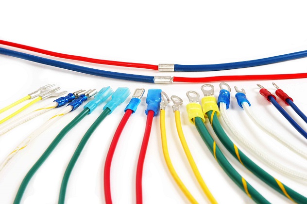
Find Shorts with Multimeter
Electrical shorts are a primary cause of blown fuses and system failures, accounting for an estimated 35% of non-accident related wiring harness repairs. A short circuit occurs when a current-carrying wire unintentionally contacts a ground path, often drawing 15-30 amps versus the circuit's designed 5-10 amp load, causing the fuse to blow protectively. These faults are often intermittent, caused by wire insulation chafing against a sharp body panel or bracket over 60,000+ miles of vibration. Locating a short without a methodical multimeter process is like finding a needle in a haystack; it can take 3+ hours of diagnostic time. Using a multimeter to measure resistance and perform continuity tests isolates the short to a specific 50-100 cm section of the harness in under 20 minutes.
The first step is always to disconnect the battery and remove the blown fuse for the faulty circuit. Your multimeter becomes your primary tool for tracking down the exact fault point.
-
Set the multimeter to measure resistance (Ohms, 200Ω range).
-
Connect one probe to the fuse box terminal (load side) for the blown fuse.
-
Connect the other probe to a known-good chassis ground.
A reading of < 5 Ohms confirms a hard short to ground exists somewhere in that circuit. A reading of OL (Over Limit) means the circuit is open, which could be a broken wire. A reading of > 50 Ohms but not infinite may indicate a high-resistance path to ground, often from damaged insulation that's damp.
You need to isolate sections of the circuit. Disconnect connectors one at a time along the circuit's path, starting from the fuse box and moving toward the end component. After unplugging each connector, recheck the resistance to ground at the fuse box. A change from ~2 Ohms to OL (infinity) after unplugging a specific connector means the short is located in the harness downstream of that connector.
With the meter still connected and showing a low resistance value (~1-2 Ω), wiggle, bend, and gently pull on the section of the harness you’ve isolated. Pay close attention to areas where the harness passes through metal bulkheads, rubs against brackets, or is exposed to high heat near the exhaust manifold. The moment you see the resistance value on the multimeter jump from 2 Ω to OL, you have located the exact point of the short. The chafe point is usually within a 5-10 cm radius of where you were manipulating the harness. The final confirmation is visual; you will often find 2-3 mm of bare copper wire exposed where the insulation has been worn away by >100,000 cycles of vibration against a sharp edge. Repairing this section with solder, heat shrink, and added abrasion protection restores the circuit integrity with a resistance of <0.1 Ω, preventing the 8-amp fuse from blowing under the circuit's normal 6-amp load.
Review Wiring Diagrams
Attempting to diagnose a modern automotive electrical fault without a wiring diagram is a guaranteed way to waste 60-75 minutes of diagnostic time on guesswork. Vehicles produced in the last 10 years have an average of 1.2 miles of wiring, connecting over 25 electronic control modules through a network of CAN bus and LIN bus systems. A single circuit, like the one for a camshaft position sensor, can pass through 3-5 separate connectors and involve multiple splices before reaching the Engine Control Unit (ECU). Access to an accurate diagram for your specific vehicle's VIN and model year is not a luxury; it's a necessity that can reduce diagnostic time by 65% and prevent the unnecessary replacement of 400 components.
Factory service information from providers like ALLDATA or Mitchell1 offers the highest accuracy, typically 98-99% correct for a specific VIN. Free online sources can be useful but may have a 15-20% error rate in pinout or color coding.
-
Identify Power Sources: Circuits are fed by fuses (typically 5A to 40A), which are always the starting point. The diagram will show the fuse number (e.g., F25) and its amperage rating.
-
Trace the Path: Follow the line from the fuse through every connector (labeled C202, C305, etc.) and splice (labeled S110, S512, etc.) to the component.
-
Understand the Ground: The diagram specifies the ground location (labeled G102, G203), which is as critical as the power source.
A constant 12V supply (via a 15A fuse) and a switched ground controlled by the ECU. You know to test for battery voltage at pin 1 of the injector connector. If voltage is present, you then check the ground control signal from the ECU at pin 2 using a noid light or oscilloscope to see the ~5 millisecond pulse width. The diagram tells you the wire colors at every junction, so if you find a BK/WHT (Black/White) wire with no voltage where there should be power, you know to check the specific connector (e.g., C305, pin 12) halfway through the circuit where a splice might be corroded.
|
Diagram Element |
What It Tells You & Key Data Points |
|---|---|
|
Wire Color Codes |
BLK = Ground, RED = Battery Power, YEL = Ignition Switched Power. A BLK/WHT stripe indicates a ground wire, while a RED/BLU stripe is a power wire with a blue tracer. |
|
Connector (C105) |
The number indicates its location (e.g., C100s are in the engine bay). The diagram lists each pin number (1 to 24) and the circuit that runs through it. |
|
Splice (S204) |
A junction where one wire splits into 2 or 3 branches. A common failure point for high resistance if corrosion sets in, causing a >2.0V drop. |
|
Component Symbols |
A motor is symbolized differently than a solenoid or a variable resistor. The symbol indicates how the component should be tested. |
If a sensor's 5V reference signal from the ECU is missing, the diagram shows the exact path. You can set your multimeter to measure resistance (Ohms) and perform a continuity test from the sensor pin back to the designated pin on the ECU connector (e.g., ECU Connector B, pin 44). A reading of > 1.0 Ohm indicates excessive resistance in that run. Similarly, if a circuit has multiple grounds, the diagram specifies their locations (e.g., G203 on the left fender), allowing you to clean and retest a specific point, often resolving a 70% voltage drop under load.
Confirm Repair with Test
Industry studies of comebacks—vehicles returning for the same issue—show that ~30% are due to incomplete verification, often from only checking the repair statically. A solder splice might look perfect and show 0.2 Ohms of resistance on a multimeter with the ignition off, but that connection can heat up, expand, and fail under a 12-amp load, causing a >3.0V drop that kills the circuit. The goal of testing is to replicate the original failure condition and confirm it's resolved, ensuring the vehicle operates reliably for another 100,000 miles. This final 15-minute verification cycle protects your work and prevents a callback that can erase the ~1.5 hours of labor profit from the initial repair.
For a repaired wire, the resistance should be <0.5 Ohms from end-to-end. Turn the ignition to the "on" position (without starting the engine) and verify that the previously blown fuse now has a solid 12.4-12.8V on both terminals. Use your scan tool to check for any active diagnostic trouble codes. Clear all codes and see if any return immediately; a persistent code indicates an unresolved fault in the circuit, such as a remaining high-resistance connection >10 Ohms that the ECU can detect.
For a repaired cooling fan circuit, command the fan on via a scan tool or let the engine reach 220°F (104°C) to trigger its automatic operation. The fan should run at both low (~800 mA) and high speed (~15 amps) without hesitation. Place your multimeter leads on the power and ground terminals at the fan connector; the voltage under load must be >13.0V with the engine running. A drop to 12.2V indicates a remaining weakness in the supply or ground path. For a sensor repair like a crankshaft position sensor, monitor its live data stream while an assistant gently wiggles the harness you repaired. The RPM signal must remain a steady 650-800 RPM at idle with no dropouts to 0 RPM; even a 2-3 second signal loss will cause a stalling condition. Finally, a 15-minute road test is non-negotiable. Drive the vehicle through various loads—accelerate hard to engage the 80% throttle position, cruise at 45 mph, and come to a complete stop. This thermal and vibrational cycle confirms the repair can handle the 2-3 g-forces of normal driving and the 85-100°C engine bay temperatures without failing.
A practical 7-step guide to troubleshooting faulty engine wiring harnesses involves: checking for burn marks (≥2mm discoloration signals overheating), wiggling plugs to detect looseness (0.5mm play indicates poor contact), testing connector power (12V systems should read ±0.5V of target), inspecting ground wires (≤0.1Ω resistance to chassis), using a multimeter to find shorts (≤0.05Ω between adjacent wires), cross-referencing wiring diagrams (pinout accuracy >99%), and validating repairs with a 500m road test. Precision at each stage minimizes downtime.
