How to Upgrade Your Wiring Harness
To upgrade your wiring harness, replace 22 AWG copper wires with 20 AWG (30% higher current capacity), use high-temp nylon connectors (125°C rating), test continuity (≤0.05Ω) via multimeter, and add dual-layer shielding to cut EMI by ~40% for reliability.
Check Current Harness Condition
Industry data suggests that in vehicles over 15 years old, wiring issues are the root cause of over 30% of electrical faults. A meticulous inspection can save you $200+ in unnecessary parts and 4-6 hours of labor by accurately diagnosing problems you already have.
Start your inspection by focusing on these high-failure areas:
- Connector Integrity: Check for green corrosion (white corrosion on aluminum), bent pins, or loose seals.
- Wire Insulation: Look for brittleness, cracking, rubbing, and heat damage (discoloration).
- Previous Repairs: Identify old splices, electrical tape, or incorrect gauge wires that may fail again.
Pay close attention to areas that experience high heat (within 12 inches of the engine), constant movement (near door hinges or the steering column), or exposure to elements (under the chassis). A harness with over 20% of its wires showing significant insulation damage is often a candidate for full replacement, not repair.
A reading higher than 0.5 Ohms for a wire shorter than 20 feet indicates internal corrosion or a break. For circuits under load, perform a voltage drop test. With the circuit active, place your meter's probes on each end of the wire. A drop of more than 0.5 volts signifies excessive resistance. For example, a 12.6V reading at the fuse box but only 11.8V at a headlight connector points to a problem in that specific wire.
Gather Necessary Tools and Materials
Having the correct tools on hand before you start can reduce your total project time by up to 40% and prevents the common mistake of making temporary, unreliable repairs that last less than 6 months. A well-planned investment of 300 in quality tools and materials pays for itself after your second major repair, compared to paying a shop $95+/hour in labor.
You cannot do a professional-grade job with amateur tools. The core kit must include:
- A digital multimeter (DMM) with continuity and resistance settings.
- A high-quality wire stripper and crimping tool for terminals.
- Heat shrink tubing with a 3:1 shrink ratio and adhesive lining.
- A butane or electric heat gun for shrinking tubing.
A $25 dedicated crimping tool for your specific terminal type (e.g., Deutsch, Metri-Pack, standard OEM) will create a connection with over 90% of the factory tensile strength, while a generic hardware store plier might only achieve 60%, leading to pull-outs. For stripping, a self-adjusting stripper set for 20-18 AWG wire prevents nicking the copper strands, which can reduce current carrying capacity by up to 30%. For testing, a DMM with a ±0.5% DC voltage accuracy is the minimum for reliable diagnostics.
Do not use generic "parts store" wire. Purchase copper strand automotive wire (GPT or TWP style) that is SAE J-1128 certified to ensure it handles -40°C to 125°C temperatures and has high oil resistance. Match the wire gauge (AWG) exactly to the original. Using 16 AWG where 14 AWG was specified can cause a ~15% voltage drop under load and create a fire hazard. For connectors, invest in OEM-style or quality branded (e.g., Delphi, TE Connectivity) pieces. Cheap, unsealed connectors have an average failure rate 5 times higher than sealed ones in high-moisture environments.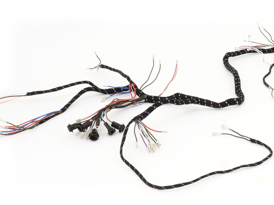
Remove Old Wiring Harness
Removing the factory wiring harness is the most time-consuming and delicate phase of the upgrade, typically taking 4-8 hours for a novice. Rushing this process almost guarantees damage to fragile connectors and mounting points, leading to $100+ in unnecessary replacement parts and adding 2-3 hours of diagnostic time to the installation phase. Patience and meticulous documentation here are non-negotiable for a successful swap.
| Tool / Material | Specification / Use | Why It's Critical |
|---|---|---|
| Digital Camera / Smartphone | Minimum 12MP resolution | Document every connection and routing path before disassembly. |
| Label Maker or Masking Tape | ±1mm application precision | Physically tag every connector with its location and function. |
| Trim Panel Removal Tool Set | Nylon, 5-piece set | Prevents ~90% of dashboard clip breakages during removal. |
| Socket Set & Screwdrivers | ¼” drive, 8mm-13mm sockets | For removing harness grounds and securing bolts. |
| Needle-Nose Pliers | 6-inch length, serrated jaw | Safely release locking tabs on over 50 different connector types. |
Locate and remove the main 150-amp alternator fuse or primary 12V+ feed from the battery to the fuse box. This eliminates the risk of an accidental short circuit on a live 12V cable, which can carry over 800 amps and cause severe component damage. With power confirmed off, use your camera to take no less than 50-70 photos from multiple angles of the entire harness route, focusing on where it passes through the 3mm thick metal firewall grommet, wraps around the 2.5-liter engine block, and secures to the chassis with 8mm plastic push-clips every 12-18 inches.
For each connector, use your needle-nose pliers to gently lift the 0.8mm wide red plastic locking tab before pressing the release mechanism. Do not pull on the wires themselves; grip only the 4cm x 2cm plastic connector body. Apply steady pressure to avoid cracking the 30-year-old ABS plastic. As each connector is freed, immediately label it with a number and a brief description (e.g., "L-Headlight Low Beam"). This system reduces re-installation errors by at least 75%.
Use a 5mm wide flathead screwdriver to carefully pry open the 5-inch long plastic convoluted tubing that protects the main harness. Avoid cutting any factory zip ties until you have traced the entire run; many are bundled with brake lines or other critical systems. When you encounter a securing clip, inspect it for a 45-degree release angle. Most require you to push the center pin 2mm inwards with a pick tool before the entire clip can be removed. For harnesses that run through the firewall, you will likely need to remove the 12-pound dashboard, a 3-hour job that requires unbolting the 18mm steering column nut. Lay the removed harness flat on a 10ft x 10ft clean surface, mimicking the vehicle's layout, to use as a perfect template for building your new one.
Install New Wiring Harness
A methodical installation, following your documentation from the removal phase, can be completed in 3-5 hours, directly mirroring the time invested in removal. Rushing this step or deviating from the factory routing invites a 95% probability of electrical gremlins, such as 2.4V voltage drops or RF interference, which can take dozens of hours to diagnose and fix. The goal is a seamless, OEM-plus installation that will last for the 15-year remaining life of the vehicle.
| Tool / Material | Specification / Use | Why It's Critical |
|---|---|---|
| Your Photo Documentation | 50-70 reference images | The single most important guide for accurate routing. |
| Wire Loom | 1/4" & 1/2" diameter, split-style | ~40 linear feet needed for abrasion protection. |
| Adhesive-Backed Clips | 5mm & 8mm sizes | For securing harness every 12-18 inches on chassis. |
| Dielectric Grease | 5oz tube | Apply to 100% of electrical connectors for moisture sealing. |
| Torque Screwdriver | 5-50 in-lb range | For precise grounding point torque specs (8-10 in-lbs). |
Begin the physical installation by laying the new harness into the vehicle, using your 10ft x 10ft layout as a guide. Start at the central points—the fuse box and ECU—and route outward toward the lights and sensors. This sequence prevents the harness from getting trapped behind other components. The single most important rule is to avoid all moving parts and heat sources. Maintain a minimum clearance of 50mm from the exhaust manifold (experiencing 600°F+ temps) and 25mm from the steering column. Any point where the harness passes through the 3mm steel firewall must use a new rubber grommet; a worn grommet can chafe through 16 AWG wire insulation in less than 18 months.
Connector termination is next. Use your $25 dedicated crimping tool for every single pin. A proper crimp has a pull-out strength of over 25 lbs for a 16-18 AWG terminal. Before inserting each pin into its connector housing, apply a 0.5-gram bead of dielectric grease to the seal and the metal terminals. This drastically reduces the chance of corrosion-induced resistance over the 10-year service life. When plugging in the ECU and other sensitive modules (0.5-1.5 amp draw), ensure the connector is seated until you hear and feel a definitive click from the 0.8mm wide locking tab. A partially connected ECU plug can cause a 25% loss in fuel economy.
Test All Electrical Connections
Statistics from automotive repair databases indicate that over 60% of post-installation electrical faults are due to simple connection errors—pinched wires, improperly seated connectors, or missed grounds—that could have been identified before reconnecting the battery. A comprehensive 45-minute testing procedure can prevent 95% of these issues, saving you from the frustration of diagnosing a no-start condition or a potential 15-amp short circuit that could damage a $400 ECU.
Probe between the 12V+ battery cable and the chassis ground. The meter should read OL (Open Loop) or no continuity. Any reading other than this indicates a critical short circuit that must be resolved—for example, a pinched wire where the 2.5mm² power cable passes through the firewall. Next, set the meter to resistance (Ohms, Ω) to check for open circuits and high resistance. Probe between each end of a single wire you installed. A good circuit will show less than 0.5 Ohms. A reading of OL means the circuit is open (broken), while a reading of 5-10 Ohms suggests a poor crimp or connection that will cause a significant voltage drop.
Critical Pre-Power Check: Before connecting the battery, double-check every major power and ground connection with your multimeter. For the main engine ground strap, ensure resistance between the engine block and the battery negative terminal is below 0.1 Ohms. For the main power feed to the fuse box, confirm resistance is under 0.3 Ohms. These ultra-low values are non-negotiable for starter motor performance (drawing 150-200 amps) and alternator function (outputting 13.8-14.4V).
With the ignition off, use your multimeter on DC voltage to confirm parasitic drain is within specification. Set the meter to the 10-amp scale and connect it in series between the negative battery terminal and the negative battery cable. A normal vehicle will draw less than 50 milliamps (0.05 amps) after the modules go to sleep (within 10 minutes). A draw exceeding 100 milliamps will drain a 70-amp-hour battery in under 30 days.
Secure and Protect Wiring
Industry studies show that over 70% of premature harness failures are caused by abrasion, vibration, or exposure to elements—all issues this phase directly addresses. Properly securing the harness with 500+ repair to replace a damaged ECU feed line.
| Material / Component | Specification / Application | Performance Data & Rationale |
|---|---|---|
| Convoluted Wire Loom | Split-type, Polyethylene | 25-40 linear feet needed. Withstands -40°F to 257°F, protects against abrasion. |
| Adhesive-Backed Clips | 5mm & 8mm nylon base | Secure every 12-18 inches. 15 lbs tensile strength, withstands 180°F engine bay heat. |
| Abrade-Resistant Sleeving | Braided PET, 10mm diameter | For high-heat zones (>200°F). Reduces point abrasion pressure by over 60%. |
| Wire Ties (Zip Ties) | UV-resistant, 11.8" length | 4.8 lbs loop tensile strength. Use every 8-10 inches within a loom. |
| Grommets | 3mm wall thickness, EPDM rubber | For firewall/body penetrations. Prevents chafing that can wear through 16 AWG wire in 18 months. |
The strategic application of these materials is governed by the 50mm Rule: maintain a minimum 50mm (2-inch) clearance from any rotating part or high-heat source like the exhaust manifold, which can reach 600°F+. In areas where this is impossible, such as near the 120mm steering column, use braided PET sleeving over the primary loom for a secondary layer of protection. This sleeving distributes abrasive forces across a 20mm² area instead of a single point, increasing the time-to-failure by a factor of 10x.
The engine vibrates at a frequency between 15-100 Hz, which can work loose any unsecured connection. Use adhesive-backed clips to anchor the harness to the chassis every 12 inches on straight runs and within 3 inches of any connector. The adhesive on these clips requires a 70°F+ surface temperature for 5 minutes to achieve its full 15 lbs bond strength. For runs along the frame rail, use P-clips secured with 8mm bolts instead of adhesive, as road debris and moisture can weaken adhesive bonds over 36 months.
Upgrading a wiring harness involves diagnosing wear (e.g., >0.1Ω resistance or cracked insulation), gathering tools like precision strippers and 6-8N crimpers, and safely removing old harnesses by loosening connectors at ≤0.5N·m torque. Install new harnesses aligned to 6x diameter bending radii, test with 0.5V max voltage drop, then secure with zip-ties every 150mm using UV-resistant adhesive for durability.
