Molex Connector Harness Customization Guide | Custom Length, Color
Molex harnesses support length customization (±2mm accuracy) and 10 standard color choices, with Pantone color matching available.
All cable jackets pass a 48-hour UV aging test to ensure color fastness.
Length
The accuracy of the harness length directly determines the system's electrical performance and mechanical reliability.
A length deviation exceeding 5% can cause a voltage drop of more than 3%, or generate residual stress exceeding 10 Newtons on the connector terminals.
For high-frequency signals, the length error needs to be controlled within ±0.5mm to maintain signal synchronization.
Electrical Performance
1. DC Resistance and Voltage Drop
Formula: Voltage Drop (ΔV) = Current (I) × Wire Resistance (R)
The resistance of a wire is determined by the formula: R = ρ × L / A (ρ is resistivity, L is length, A is cross-sectional area). Resistance is proportional to length and inversely proportional to cross-sectional area (wire gauge).
Practical Scenario Calculation:
Assume a 12V DC fan with a normal operating current of 2A, using AWG 22 wire (cross-sectional area approx. 0.326 mm², resistance per meter approx. 0.053 ohms).
| Harness Length | Total Resistance (round trip) | Voltage Drop | Voltage at Fan End | Result Analysis |
|---|---|---|---|---|
| 0.5 meters | 0.053 Ω | 0.21 V | 11.79 V | Acceptable, minimal impact |
| 2 meters | 0.212 Ω | 0.42 V | 11.58 V | Need to confirm fan's minimum operating voltage |
| 5 meters | 0.53 Ω | 1.06 V | 10.94 V | May be close to the fan's undervoltage protection point, causing startup difficulty or unstable operation |
Solution:
If long-distance power transmission is unavoidable, the wire gauge must be increased to reduce resistance.
Changing the wire from AWG 22 to AWG 18 (cross-sectional area approx. 0.823 mm², resistance per meter approx. 0.021 ohms), the total voltage drop for a 5-meter length would be reduced to about 0.42V, the terminal voltage becomes 11.58V, significantly improving system stability.
Design Recommendation: When planning power harnesses, aim to control the voltage drop within 3% of the load's operating voltage range. For example, for a 12V system, the allowable voltage drop should not exceed 0.36V.
2. AC Characteristics and Signal Integrity
When transmitting high-frequency AC signals or high-speed data, the harness is no longer just a wire but behaves as a complex transmission line model, its characteristics determined by resistance (R), inductance (L), capacitance (C), and conductance (G).
Main Impact Areas:
Signal Attenuation:
Example: USB 3.0 signal frequency is as high as 5 GHz. The standard specifies that the length of passive copper cables typically should not exceed 3 meters. Beyond this length, signal quality degrades sharply, and reliable communication cannot be guaranteed.
Characteristic Impedance:
- Impedance Mismatch: If the harness's characteristic impedance does not match the driver's output impedance or the receiver's input impedance, signals will reflect at the connection points. These reflected signals superimpose with the original signal, causing ringing and overshoot, which can lead to data errors in severe cases.
- Requirement: High-speed differential pairs (e.g., HDMI, Ethernet) require strict impedance control, with tolerances typically needing to be within ±10%.
Delay and Skew:
Signals propagate along the harness at a finite speed, approximately 2/3 the speed of light.
For very long harnesses (e.g., over 10 meters), this propagation delay must be considered in precision synchronization systems.
Furthermore, in differential pairs, if there is a length difference between the D+ and D- wires, it causes a difference in signal arrival time, known as "skew."
The length matching tolerance is typically required to be within 0.5 millimeters.
Wiring Strategies to Improve Signal Integrity:
- For high-speed signals, prioritize specially designed shielded twisted pairs (STP) or coaxial cables.
- Maintain a tight twist pitch (for twisted pairs).
- Ensure the harness routing is kept away from strong noise sources like motors and power transformers.
3. Current Carrying Capacity and Temperature Rise
Wires heat up when carrying current. Excessive current or too thin a gauge can cause the harness temperature to rise, posing a safety hazard. The wire's ampacity depends on:
- Wire Gauge (AWG): A smaller number indicates a thicker wire with higher current-carrying capacity.
- Insulation Material's Rated Temperature: For example, PVC is typically 105°C, while Teflon can withstand up to 200°C.
- Wiring Environment: Wires bundled together (like in a harness) dissipate heat less effectively than single wires and require derating.
Mechanical Considerations
1. Stress Analysis and Relief
The mechanical stress the harness endures during installation needs to be controlled within the material's elastic range. The following is a stress analysis for different installation states:
| Installation State | Force on Connector Terminals | Internal Stress in Wires | Potential Failure Mode |
|---|---|---|---|
| Too Short (20mm short) | 15-25N constant tensile force | Copper strand stretching/deformation | Increased terminal contact resistance, connector detachment |
| Optimal Length (±5mm) | <5N slight tension | No permanent deformation | Long-term stable connection |
| Too Long (50mm excess) | No tension but cable sagging | Stress concentration at bend points | Insulation fatigue cracking |
Solutions:
• Set a fixed point 150mm behind the connector to absorb mating/unmating stress.
• Maintain a natural bend radius greater than 5 times the harness diameter (e.g., 20mm radius for a 4mm OD harness).
• For dynamic bending applications, use multi-strand fine copper wires (0.08mm diameter) instead of single-strand thick copper wires.
2. Routing Path Optimization
Typical wiring requirements for industrial equipment:
Cabinet Internal Wiring:
- Set a fixed point every 300mm along the metal frame.
- Maintain a minimum 15mm distance from heat sources (heat sinks, motors).
- Avoid interference with moving parts (door hinges, slides), reserve a 10mm safety gap.
Mobile Equipment Wiring:
- Use flexible cables (bending life >1 million cycles).
- Use connectors with strain relief (e.g., Molex Micro-Fit 3.0).
- Manage excess length using cable carriers or retractors.
3. Environmental Adaptability Design
Vibration Environment (e.g., Engine Bay):
- Natural frequency should avoid the equipment's primary vibration frequency (typically 20-200Hz).
- Use anti-vibration sleeves to reduce high-frequency vibration transmission.
- Set a damping fixed point every 150mm.
Thermal Cycling Environment:
- Harness length must account for thermal expansion/contraction over a 50°C temperature range.
- Thermal expansion coefficient for PVC material harness is 0.07mm/m/°C.
- For a 2-meter length and 50°C temperature difference, the length change is 7mm.
4. Connector Interface Protection
Strain Relief Design Standards:
- Right-angle connectors: Withstand 25 vertical mating cycles (50N force).
- Straight connectors: Withstand 50 axial mating cycles (70N force).
- A fixed point must be set within 20mm behind the connector.
5. Maintainability and Replaceability
Service Loop Design Parameters:
- Standard maintenance: Reserve 5% of harness length as service allowance.
- High-frequency maintenance: Reserve 10-15% allowance for easy equipment movement during repair.
- Minimum service radius: 8 times the harness outer diameter (e.g., 48mm radius for 6mm OD).
Test Validation Requirements:
- Bend test: Resistance change <5% after 5000 ±90° bends.
- Pull test: Withstand 2x installation pull force (approx. 40N) for 60 seconds.
- Vibration test: No mechanical damage after 5-500Hz sweep vibration.
Precise Measurement
1. Selection and Accuracy of Measuring Tools
Using inappropriate tools introduces systematic errors. Common tools and their applicable scenarios are as follows:
| Measuring Tool | Typical Accuracy | Applicable Scenario | Limitations |
|---|---|---|---|
| Standard Tape Measure (cloth/steel) | ±1 mm | Rough measurement for lengths over 1 meter | Tape sag, parallax error |
| Rigid Steel Ruler | ±0.5 mm | Short distances (<1m) or as a marking tool | Cannot measure curved paths |
| Laser Distance Meter | ±1.5 mm | Macro layout in large spaces like equipment cabinets | Cannot track specific cable bending paths |
| Digital Caliper | ±0.02 mm | Measuring dimensions like connector mating depth | Limited measuring range (typically <200mm) |
Operation Key Points: When measuring, keep the tool parallel to the measured path to avoid cosine error from angles. For measurements over 2 meters, two-person operation is recommended to ensure the tape is straight and flush against the intended path.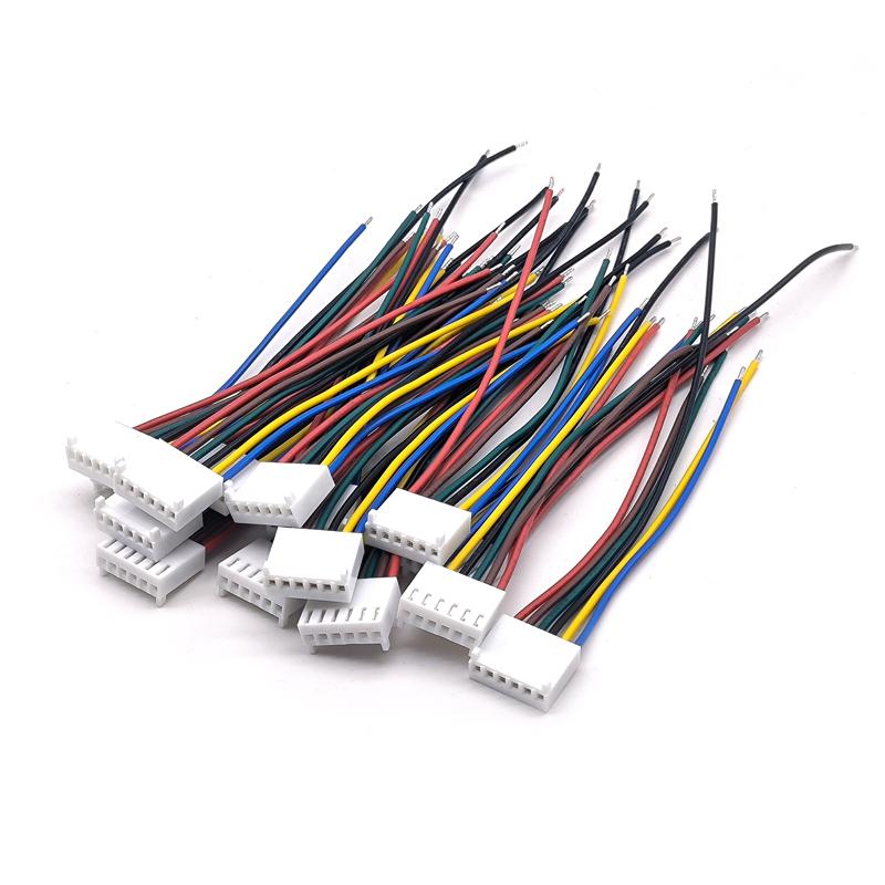
2. Path Simulation and Length Calculation
Step-by-step Operation Process:
- Path Planning:
- Simulate the harness path on the physical equipment or an accurate 3D model using a flexible string or thin wire.
- Route strictly according to existing conduits, clamps, and pass-through holes, bypassing all obstacles.
- Endpoint Marking:
- Precisely mark the mating face position of the connector housing at both ends of the string with a marker. This is not the wire termination point, but the physical location the connector needs to reach.
- Total Length Calculation:
- Straighten the string (but do not stretch it) and measure the distance between the marks with a calibrated steel ruler. This is the "Path Reference Length" (L_path).
- Adding Allowance:
- Connector Mating Allowance: At each connector end, extra length is needed for easy manual mating/unmating and stress relief. This value is typically 50mm to 100mm. Calculation formula: L_total = L_path + (N_connectors × A), where A is the single-end allowance (e.g., 75mm), N_connectors is the number of connectors.
- Bend Radius Compensation: If there are 90-degree bends in the path, ensure the harness bend radius is greater than 5 times its outer diameter (e.g., R ≥ 20mm for a 4mm OD harness). When calculating the length around a bend, use the arc length (πR/2), not the straight-line distance.
3. Environmental Factors and Tolerance Setting
- Temperature Influence: Harness materials expand and contract with heat. The coefficient of thermal expansion for PVC jacketing is approximately 0.07 mm/m/°C. If there is a 30°C difference between the operating environment and the measurement workshop, the length change for a 2-meter harness is: 0.07 × 2 × 30 = 4.2 mm.
- Tolerance Setting: Length tolerance must be explicitly specified to the manufacturer. For example, "Length: 1250 mm, Tolerance: +5/ -0 mm" means the harness can be up to 5mm longer, but must not be shorter. A typical accuracy requirement is: Length < 1m: tolerance ±2mm; Length 1-5m: tolerance ±5mm; Length >5m: tolerance ±0.1%.
Color
Selecting the appropriate color for Molex connector harnesses can directly improve production efficiency and system reliability.
Following ANSI/TIA standard color coding can increase installers' wire identification speed by approximately 40% and reduce connection errors by over 30%.
For example, using UL1007 certified cables provides over 50 standard color options, with color difference strictly controlled within the industrial standard of ΔE < 2.0, ensuring consistency across batches.
Technical Identification
Using Color to Replace Complex Wiring Diagrams
On automotive manufacturing or industrial equipment assembly lines, installers may need to complete hundreds of connection points within hours. If every wire is black, they must constantly refer to complex wiring diagrams, checking wire numbers one by one—a slow and error-prone process.
- Data indicates: After implementing color coding, installers' speed in identifying the correct wire increases by approximately 40%. For example, in a harness with 20 connection points, identifying and connecting based on color averages about 3 seconds per point; whereas relying on reading wire numbers and comparing drawings might take over 5 seconds per point. This saves over 40 seconds for the entire harness installation.
- Error Rate Decrease: Visual differentiation significantly reduces human error. An industrial automation company in the US reported that after introducing a standard color scheme of Red (power), Black (ground), Blue (signal), Yellow (sensor) for their robot control cabinet harnesses, the production line wiring error rate dropped from 0.5% to below 0.1%.
Following International Standards to Establish a Common Language
To ensure engineers from different manufacturers and countries can understand color meanings without barriers, adhering to established international standards is crucial.
- Industrial Control Field: In PLC (Programmable Logic Controller) systems, the following conventions are commonly used:
- Red: 24VDC positive power supply.
- Black: 0VDC or common ground (DC Common).
- Blue: Often used for analog signals (e.g., 0-10V, 4-20mA) or low-voltage DC power.
- Green/Yellow: Reserved specifically for the protective earth (Safety Ground/Equipment Grounding Conductor).
- Electronics and Board Level: Within equipment, color coding can be more refined:
- Violet: May represent negative voltages like -5V or -12V.
- Grey: May be used for -Vcc or specific negative power rails.
- White: Sometimes used for negative signals or as a complementary color for data lines.
Efficient Wiring in Compact Spaces
Modern electronic devices, such as servers and network switches, have extremely limited internal space. Color coding makes it possible to trace specific wires within dense harnesses.
| Scenario | Challenge | Color Solution |
|---|---|---|
| Server Rack Wiring | Dozens of network, power, and management cables tangled together. | Use different colored SFP+ fiber jumpers to distinguish management, data, and backup networks. Use red power cords to identify redundant power paths. |
| Automotive Door Harness | Multiple functional lines (window control, door lock, speaker, mirror adjustment) concentrated in a narrow space. | Assign a primary color to each function, with secondary identification using colored rings or stripes. E.g., Green for window control, add white stripe for driver switch wire, red stripe for passenger switch wire. |
Improving Troubleshooting Efficiency with Color
When a system fails, repair time is critical. Color coding can reduce the average fault diagnosis time by nearly 50%.
Maintenance engineers don't need to measure hundreds of black wires one by one; they can directly locate suspicious lines based on the system function.
For example, if a sensor on an injection molding machine fails.
If all sensor wires in the harness are yellow, the technician can directly trace the yellow harness back to the I/O module to check power and signal, greatly narrowing down the troubleshooting scope.
In aerospace maintenance, this standardization and visualization is a mandatory requirement to ensure the highest safety and maintenance efficiency.
Brand Identity
Establishing a Unified Visual Image
Many global corporations incorporate brand colors into both the exterior and interior of their products.
For example, a brand's signature yellow appears not only on the product casing but also on the internal connection harnesses.
This approach ensures a consistent visual experience from the outside in.
When service engineers or end-users open the equipment, this consistency reinforces recognition of the brand's rigor.
For large companies with multiple product lines, a color system can be used to unify brand image management.
Products in different fields like medical devices, professional audio, and network hardware can share the same brand color palette but be differentiated through primary and secondary color combinations.
Managing Product Lines with Color
In complex product portfolios, color is an efficient visual management tool.
Companies can define different harness color strategies for products with different positioning.
Flagship models might use dark harnesses with custom-colored connectors to highlight premium quality; whereas standard models adopt a more cost-effective standard color scheme.
This practice is particularly common in the automotive industry.
Different trim levels of the same car model may have different harness colors in the engine bay, facilitating quick identification and assembly on the production line.
These internally used color codes can even become a reference in the used car market for determining the vehicle's original configuration.
Aiding Channel Management and Anti-Counterfeiting Protection
Custom harness colors for different sales regions or channels can serve as internal markers for channel management.
These subtle differences are hard for average consumers to detect but have practical value for manufacturers tracking product flow and managing market segmentation.
In some cases, combining custom colors with special markings increases the difficulty of counterfeiting.
Copying the physical structure of a connector is relatively easy, but precisely matching a unique color and surface texture is a higher barrier.
This provides an additional layer of intellectual property protection for the brand.
Technical Considerations for Achieving Color Consistency
Accurately applying brand colors to harnesses requires precise color management.
This typically requires communication using standard color systems like Pantone or RAL.
Color samples provided by the manufacturer need to be compared against the color standard under a standard light booth to ensure the color difference ΔE value is within an acceptable range (typically ΔE < 2.0).
Ambient lighting significantly affects color perception. The internal harness color of devices displayed in retail environments needs to appear accurate under store lighting.
Therefore, color selection must consider the product's final usage scenario.
Balancing Cost and Value of Custom Colors
Choosing colors outside the standard library usually incurs additional costs, including color matching fees, minimum order quantities, etc.
Companies need to assess whether the brand value enhancement from custom colors justifies these incremental costs.
For products with annual production in the hundreds of thousands, even a few cents increase per harness adds up significantly.
The decision requires comprehensive consideration of brand positioning, product price, and expected benefits.
Maintenance Cost
Reducing Fault Diagnosis Time
When equipment fails, the first step for maintenance personnel is to locate the source of the problem.
In an electrical cabinet filled with messy harnesses, if all wires are black, technicians must use a multimeter to measure each one—a process that can take over 60% of the total repair time.
- Data Example: Studies show that after implementing standard color coding (e.g., Red-Power, Black-Ground, Blue-Signal, Yellow-Control), the average time for technicians to locate a faulty circuit is reduced by about 40%. For a complex system with 200 connection points, each diagnosis could save 45 minutes to 1 hour.
- Greater Benefit in Complex Systems: The role of color coding is even more significant in data center server racks or automated production lines. By using different colored harnesses and jumpers for different functional modules (e.g., network switches, PDUs, servers), maintenance personnel can quickly identify the target area from several meters away, instead of blindly searching through hundreds of cables.
Reducing Error Rates in Repair Operations
- Error Cost Comparison: A mistakenly connected 24V DC sensor wire, if incorrectly connected to a 120V AC circuit, can instantly damage sensors and controller ports worth thousands of dollars, leading to longer downtime. Using a unique color (e.g., orange for all sensor wires) provides a double-check for the operator. After repair, a simple visual inspection can confirm if the connection is correct, potentially reducing secondary error rates by over 70%.
- Simplifying Reverse Engineering: For upgrading or retrofitting old equipment, clearly colored harnesses significantly reduce the effort required to understand the original circuit logic. Technicians can quickly draw circuit flowcharts, and quotes and time estimates for upgrade projects become more accurate.
Reducing Dependence on Highly Skilled Personnel
- Human Resource Optimization: For example, in wind farm maintenance, if all power harnesses in the tower are red and all signal harnesses are blue, the field team can follow a simple rule like "red harness connects to power terminal, blue harness connects to controller" for replacements.
- Reducing Training Costs: Color coding helps new employees understand and remember the system structure more easily during training. The training cycle can be shortened by about 25%, and the cost of training aids and consumables is correspondingly reduced.
Optimizing Spare Parts Inventory Management
- Warehousing Efficiency Improvement: In the spare parts warehouse, administrators can manage harnesses using both color and part number identification. For example, the shelf for "P/N: XYZ-001, Red, 10A Power Wire" is immediately distinguishable from the shelf for "P/N: XYZ-002, Blue, Signal Wire".
- Procurement Accuracy: When field personnel need to order spare parts, describing "a 10-foot long red power wire" is less prone to communication errors than providing only a part number.
