Molex Connector Harness Customization Guide | Manufacturing process, Quality&Price
Molex harness customization includes the entire process of mold opening, injection molding, and assembly, passes UL certification and 96-hour salt spray test. The price for orders starting from 100 pieces is approximately 85 RMB, and the price adjusts based on gold plating thickness and wire gauge.
Manufacturing process
Molex connector harness customization manufacturing begins with precise engineering design and ends with 100% functional verification.
The entire process involves over 15 steps, with the goal of transforming cables, terminals, and housings into an integrated component that fully meets specifications in electrical, mechanical, and environmental performance.
Taking a 50-core industrial robot harness as an example, its manufacturing cycle is typically 3-5 working days, and the crimping accuracy for terminals needs to be controlled within a cross-sectional tolerance of ±0.1 mm² to ensure conductive stability.
Design
Confirming the Requirement List
Design starts with a complete requirement collection list. Engineers need to clarify the following parameters:
-
Electrical Performance: Includes rated current (0.5A to 20A per conductor), voltage level (12V to 600V), shielding requirements (a shield with ≥85% coverage can reduce EMI interference by over 30dB).
-
Mechanical Specifications: Bend radius (not less than 5 times the cable diameter for fixed installation, 10 times for moving applications), tensile strength (e.g., ≥150N), vibration rating (e.g., frequency range 0-2000Hz).
-
Environmental Indicators: Operating temperature range (high-temperature resistant materials for -40℃ to 125℃), protection rating (IP67 sealed connectors can withstand immersion in 1 meter of water for 30 minutes), types of chemical resistance (engine oil, coolant, etc.).
-
Compliance Certifications: Must meet regional certifications like UL, CE; automotive applications need to comply with standards like ISO 6722.
Creating Drawing Documents
All design information is materialized through the following documents:
-
Wiring Diagram: Uses vector graphics to mark the start and end points of each wire, employing international standard color codes (e.g., GN for green, BK for black).
-
3D Harness Design: Simulates the actual path of the harness within the equipment using software like SolidWorks, checking the minimum clearance (maintain ≥3mm safe distance) from adjacent components.
-
Terminal Specification Drawing: Annotates the cross-sectional dimensions of the crimp area; crimp height tolerance is typically controlled within ±0.05mm.
Creating Prototypes for Validation
The prototype stage validates design feasibility with physical objects:
-
Rapid Prototyping: Uses 3D printing to create connector housing prototypes, verifying the assembly sequence.
-
Functional Testing: Performs preliminary continuity testing (checking for open/short circuits) and insulation resistance testing (requirement ≥100MΩ) on the prototype.
-
Assembly Verification: Records assembly time, assesses if special tools are needed (e.g., crimping dies for special sizes).
Manufacturability Analysis
Evaluates manufacturing feasibility before mass production:
-
Labor Time Assessment: Calculates standard time for each process (e.g., crimping one terminal takes 15 seconds, assembling one connector takes 2 minutes).
-
Tolerance Analysis: Analyzes the cumulative effect of all dimensional tolerances to ensure the total assembly error is within the allowable range.
-
Test Point Design: Clearly marks the locations of test access points required for 100% inspection on the drawing.
Document Version Control
Uses a revision number system to control document changes:
-
Major changes (e.g., material substitution) increment the integer version (V1.0 → V2.0).
-
Minor changes (e.g., annotation adjustments) increment the decimal place (V1.1 → V1.2).
-
Each change records the change content, date, and approver's signature.
Electrical Connection
The Junction Point of Terminal and Wire
Terminal crimping is the primary method for forming electrical connections. This process is completed within milliseconds using specialized dies:
-
Crimp Cross-Section Analysis: A qualified crimp cross-section shows the copper strands of the wire forming a uniform deformation with the terminal metal. For a 0.75 mm² wire, the crimp height is typically set at 0.8 mm, with a tolerance range of ±0.03 mm.
-
Electrical Performance Standards: According to the USCAR-21 standard, the resistance increase at the crimp point should not exceed 0.5 milliohms. For a 22 AWG wire with an initial resistance of about 0.05 ohms/meter, the crimp point resistance increase should be less than 1%.
-
Mechanical Strength Test: Uses a force gauge to measure the retention force of the crimp point. The pull-out force for an 18 AWG wire with a standard terminal needs to be over 70 Newtons, equivalent to withstanding a static pull of 7 kg.
Connector Contact System
When the terminal is inserted into the connector housing, a second connection point is formed:
-
Contact Normal Force: The spring fingers inside the connector provide continuous normal force on the terminal, typically in the range of 50-150 grams-force.
-
Plating Impact:
-
Tin-plated terminals have a contact resistance of about 2-5 milliohms, suitable for most commercial applications.
-
Gold-plated terminals can reduce contact resistance to 1-3 milliohms, used for signal transmission or high-reliability applications.
-
-
Mating Cycle Rating: Standard connectors are rated for 50 mating cycles; high-quality versions can exceed 250 cycles.
Shield Termination Methods
High-frequency or sensitive signal lines require complete shield connection:
-
Shield Ferrule Crimping: The shield braid is evenly flared 360 degrees and then crimped using a specialized shield ferrule. Shield coverage should be over 95%, avoiding a "pigtail" braiding method.
-
Shield Grounding Resistance: Measured with a spectrum analyzer, the transfer impedance of the shield connection point should be less than 10 milliohms at 100 MHz.
-
Shield Termination Method Comparison:
Termination Method Suitable Frequency Installation Complexity Shield Ferrule Crimp DC-1GHz Medium Conductive Adhesive Seal DC-6GHz High Metal Shell Direct Clamp DC-10GHz Low
Environmental Protection of Connection Points
Electrical connections need to be isolated from the external environment:
-
Insulation Material Selection: PVC insulation sleeving can withstand a maximum operating temperature of 105°C, while silicone material can tolerate temperatures up to 200°C.
-
Sealing Level Verification:
-
IP67 Rating Test: Immerse the mated connector in 1 meter of water for 30 minutes; no water droplets should enter the interior.
-
Air Tightness Test: Apply 0.5 Bar pressure, maintain for 3 minutes; pressure drop should not exceed 5%.
-
-
Waterproof Connector Structure: Multi-layer seal design includes rear seal of the terminal, connector mating interface seal, and cable outlet seal.
Heat shrink tubing is a common external protection method, with a shrinkage ratio typically 3:1 or 4:1, starting to shrink above 120°C to form a tight wrap.
Electrical Performance Verification Methods
Each connection point needs to pass a series of tests:
-
Micro-resistance Measurement: Uses the 4-wire Kelvin measurement method with a resolution of 0.01 milliohms, eliminating lead resistance effects.
-
High Voltage Insulation Test: Apply 1500V AC between conductor and shield for 60 seconds; leakage current must be less than 1 mA.
-
Temperature Cycling Test: Perform 1000 cycles between -40°C and 125°C; the change in connection resistance should not exceed 10% of the initial value.
Component Integration
Incoming Inspection of Components
All components need to pass a quality gate inspection before entering the production line:
-
Connector Housings: Use optical comparators to check cavity dimensions; batches with tolerances exceeding ±0.1mm are rejected.
-
Terminals: Perform cross-sectional analysis on samples to ensure gold plating thickness is within the 0.76μm-1.52μm range (complying with USCAR standard).
-
Seals: Measure Shore hardness should be 70±5, compression set should not exceed 25%.
-
Cables: Verify UL certification documents, check insulation thickness uniformity; the thinnest point should not be less than 90% of the nominal value.
Material Sorting by Order
Uses a Kanban system for material distribution:
-
Material Cart Configuration: Prepare dedicated material carts for each order based on the daily production plan.
-
Quantitative Packaging: Pre-pack small parts (like terminals) in quantities of one thousand to reduce sorting time on the line.
-
Error-Proofing Design: Use differently colored bins to distinguish similar parts (e.g., 1.0mm² and 1.5mm² wires).
Material handlers use barcode scanners to confirm material configuration at each station; the error rate is required to be below 0.01%.
Assembly Process Flow Design
Different assembly strategies are adopted based on harness complexity:
| Harness Type | Process Strategy | Number of Stations | Takt Time |
|---|---|---|---|
| Simple Branch Harness | Assembly Line | 3-5 Stations | ≤30 sec/station |
| Complex Main Harness | Fixed Station Assembly | 8-12 Stations | 45-60 sec/station |
| High-Density Harness | Automated Workstation | Fully Automated | 20 sec/piece |
Each station has an assembly instruction screen displaying 3D exploded views and notes.
Connector Assembly Steps
Standard assembly sequence for multi-pin connectors:
-
Install Rear Seal: Thread the rubber seal onto the cable, ensuring the seal lip faces the inside of the connector.
-
Terminal Insertion: Use pneumatic tools to insert the wired terminal into the corresponding cavity; a "click" sound indicates primary lock engagement.
-
Activate Secondary Lock: Slide the Terminal Position Assurance (TPA) mechanism to the locked position, ensuring all terminals are fully seated.
-
Test Point Access: Retain access holes for diagnostic pins to facilitate subsequent functional testing.
Use torque screwdrivers during assembly to tighten bolts; torque is controlled at 0.6±0.1 N·m.
Branch Point Protection Treatment
Three protection methods for harness branch points:
-
Heat Shrink Tubing Sealing: Use adhesive-lined heat shrink tubing; after heating at 120°C, it forms a seal with a shear strength ≥1.5 MPa.
-
Overmolding: Inject PVC material into a mold; after molding, the pull-out force requirement is greater than 100N.
-
Mechanical Covers: Install two-part plastic covers connected by clips, capable of withstanding 50 open/close cycles.
After installing the protection device, vibration testing is required; there should be no loosening within the 10-500Hz frequency range.
Subassembly Pre-assembly
Complex harnesses use a modular assembly strategy:
-
Harness Segmentation: Divide harnesses longer than 3 meters into 2-3 segments for manufacturing.
-
Intermediate Connectors: Use waterproof intermediate connectors at segment junctions; mating force controlled between 20-40N.
-
Test Interfaces: Reserve test points on each subassembly for easy fault isolation.
Pre-assembled subassemblies require separate continuity testing; the pass rate must be above 99.95%.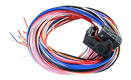
Forming the Harness Body
Using a Formboard to Fix the Geometry
The formboard is the fundamental tool for ensuring harness dimensional consistency:
-
Base Material: Uses multi-layer birch plywood, 18 mm thick, with surface flatness error less than 0.5 mm/m.
-
Locating Pin Configuration: Uses stainless steel locating pins to mark each branch point and connector position; positional tolerance is ±0.2 mm.
-
Wire Channel Design: Channel depth is determined by the harness diameter; for an 8 mm diameter main section, the channel depth is set to 4 mm to ensure wires do not pop out.
Each production line is equipped with 15-20 different formboards corresponding to different product models; changeover time is 30 minutes.
Selecting Tying Materials and Methods
Tying methods are determined by the application environment:
-
Lacing (Tying with Cord):
-
Uses special cotton or polyester cord, diameter 0.8-1.2 mm.
-
Tension per knot controlled at 15-20 Newtons; knot spacing is 5-8 times the harness diameter.
-
Suitable for high-temperature environments (continuous temperature resistance 150°C).
-
-
Cable Tie Fixing:
-
Nylon cable tie width 2.5-4.0 mm, strength ratings include 18 lb, 30 lb, 50 lb.
-
Use tension control tools to ensure consistent tightness, avoiding wire damage.
-
After cutting, the leftover tail length should be 1.5-2.0 mm to prevent sharp edges from piercing insulation.
-
-
Tape Wrapping:
-
PVC tape thickness 0.13 mm, elongation greater than 200%.
-
Wrapping overlap is 50% of the tape width; the starting end fixation length should be no less than 10 mm.
-
Abrasion-resistant cloth tape can be used for areas contacting the chassis.
-
Installing Protective Components
Protective components are selected based on the type of mechanical stress:
-
Convoluted Tubing Protection:
-
Inner diameter selected to be 15-20% larger than the harness diameter for easy threading.
-
High-temperature resistant nylon convoluted tubing can withstand continuous operating temperatures of 140°C.
-
Bend radius should not be less than 5 times the outer diameter of the tubing.
-
-
Abrasion Sleeve Installation:
-
Silicone abrasion sleeve thickness 2 mm, Shore hardness 60A.
-
Use double-sided tape at expected contact points to aid fixation.
-
After installation, perform 100 mating/unmating cycles to verify position stability.
-
-
Waterproof Sealing Treatment:
-
Use rubber grommets at harness pass-through points; compression controlled at 25-30%.
-
Apply special silicone grease to enhance sealing; usage 0.3 grams/cm.
-
Handling Harness Branch Points
Branch structures require special reinforcement:
| Branch Type | Reinforcement Method | Process Parameters |
|---|---|---|
| Sharp Angle Branch | Overmolding | Injection pressure 80-100 MPa, holding time 15 sec |
| Parallel Branch | Spiral Wrap | Wrap pitch is 1.2 times the tube diameter |
| Multi-Direction Branch | Plastic Bracket | Bracket wall thickness 1.5 mm, clip retention force > 30 Newtons |
Branch point pull test requirement: Apply 50 Newtons force for 60 seconds; displacement should be less than 2 mm.
Controlling Harness Diameter and Flexibility
The physical characteristics of the finished harness need precise control:
-
Diameter Management: Main section diameter should not exceed 25 mm; branch sections are controlled to different specifications based on the number of wires.
-
Bending Force Test: Use a push-pull gauge to measure the force required to bend a 1-meter long harness to 180°; it should not exceed 15 Newtons.
-
Flexibility Assessment: Fix one end of the harness, swing the other end left and right within a 300 mm range 1000 times; no visible cracks should appear in the wire insulation.
Measurement data is recorded and uploaded to the quality management system as a basis for process adjustment.
Performing Dimensional Verification
Final dimensional confirmation before off-line:
-
Dimensional Measurement:
-
Total length tolerance: ±5 mm / 1000 mm.
-
Branch angle: ±2 degrees.
-
Connector position: ±1.5 mm.
-
-
3D Scanning Comparison:
-
Use a laser scanner to obtain point cloud data.
-
Compare with the design model; areas with deviations exceeding 1.5 mm need adjustment.
-
Generate inspection reports; archiving period is the product lifecycle plus 5 years.
-
Quality
The quality of a custom Molex harness is reflected in a series of quantifiable metrics.
For example, a harness meeting automotive industry standards requires terminal crimp pull-off force to be consistently above 50 Newtons, 100% of circuits to pass HIPOT test (e.g., 1500VAC/60s), and a CPK value consistently greater than 1.67.
Quality Standards
How to confirm materials comply with specifications?
-
Wires: Cannot just say "high-temperature wire". Must specify standards, for example:
-
Insulation material complies with UL 1429 or UL 1571.
-
Heat resistance rating clearly defined as 105°C or 125°C.
-
Conductor structure such as 19/0.127mm (19 strands of 0.127mm diameter copper).
-
-
Connectors: Must refer to the official Molex published specifications.
-
Plastic housing material is typically PBT or Nylon, must indicate specific UL rating, e.g., UL94 V-0 (flammability rating).
-
Terminal plating thickness must be specified, e.g., pin gold plating thickness is 0.76µm (30µ inches), to ensure low contact resistance and corrosion resistance.
-
-
Auxiliary Materials:
-
Heat shrink tubing must have a temperature index of 125°C and comply with UL 224 standard.
-
Tape adhesive must pass fuel resistance tests for over 48 hours.
-
What are the specific test conditions for performance standards?
Electrical Performance
-
Insulation Resistance: Measure the resistance between each circuit and ground or other circuits at 500VDC. The pass criterion is typically ≥100 MΩ (at 25°C, 50% relative humidity).
-
Voltage Drop: Measure the voltage loss across the entire circuit at rated current (e.g., 10A). The standard may require ≤50mV.
Mechanical Performance and Environmental Endurance
-
Vibration Test: Refer to ISO 16750-3 standard. Conditions may involve a frequency sweep from 10Hz to 2000Hz for 8 hours per orthogonal axis. After testing, resistance change must not exceed 20% of initial value, and there should be no momentary interruptions (disconnects longer than 1 microsecond).
-
Thermal Shock Test: Conditions may involve cycling between -40°C (low temperature hold 30 min) and 125°C (high temperature hold 30 min) for 200 cycles.
-
Sealing (IP Rating) Test:
-
IP67: Means completely dust-tight (first digit 6) and can withstand immersion in 1 meter of water for 30 minutes without ingress (second digit 7).
-
IP6K9K: Provides higher protection, resistant to powerful water jets (9K) and dust-tight (6K).
-
What are the differences in standards across industries?
| Industry | Standards | Specific Test Examples & Pass Criteria |
|---|---|---|
| Automotive Electronics | IATF 16949 (System) / ISO 16750 (Testing) | Vibration Test: 8 hours per axis. Salt Spray Test: 96 hours, terminal corrosion area less than 5%. |
| Medical Devices | ISO 13485 (System) / IEC 60601-1 (Safety) | Leakage Current Test: Must be below 0.1mA. Biocompatibility: Materials need USP Class VI testing. |
| Industrial Automation | UL 508A (Control Panels) | Withstand Voltage Test: 1500VAC/60s. Creepage & Clearance: Must meet safety distances for the working voltage. |
How to translate standards into actionable inspections?
-
Incoming Inspection: According to standards, sample each batch of wires for dimensional measurement (conductor diameter, insulation thickness) and withstand voltage testing.
-
In-Process Inspection:
-
Crimp Height: Use a micrometer to measure 5 terminals every two hours; results must be within the tolerance specified in the datasheet (e.g., 0.65mm ±0.03mm).
-
Pull-Force Test: Perform destructive testing on samples each shift; e.g., pull force for 20AWG wire must consistently exceed 50 Newtons.
-
-
Final Inspection:
-
100% Electrical Test: Use a test bench to check continuity, insulation withstand voltage, and insulation resistance.
-
Visual Inspection: Judge based on defect classification (Critical, Major, Minor) per standards like ANSI/AAMI GEI-2014.
-
Quality Control
What needs to be checked for incoming components?
All quality control begins with verification of input materials. This work ensures every component meets design specifications before assembly begins.
-
Connector Inspection: Based on official Molex specifications, use optical comparators to measure dimensions, such as the width of the terminal insertion area; tolerance must be controlled within ±0.05mm.
-
Wire Inspection:
-
Use a micrometer to measure conductor diameter and insulation thickness, verifying against UL standard documents (e.g., UL 1061).
-
Sample from each reel for simple continuity and withstand voltage tests to rule out internal breaks or insulation defects.
-
-
Terminal Inspection: Sample and observe the plating surface under a microscope; it should be uniform and free of burrs. If necessary, use XRF fluorescence spectroscopy to spot-check gold plating thickness, confirming it meets the specified 0.76µm.
Which steps on the production line need monitoring?
Monitoring the Terminal Crimping Process
-
Crimp Height: Every two hours, the operator uses a calibrated digital micrometer to measure 5 consecutive crimps. All readings must fall within the preset tolerance range, otherwise the machine must be stopped for adjustment.
-
Pull-Force Test: Each work shift, perform destructive testing on crimped samples. For example, the pull-force test result for a 20AWG wire must consistently be greater than 50 Newtons.
-
Terminal Position Analysis: Use a dedicated TPA gauge to confirm the terminal's secondary lock mechanism is fully engaged, indicated by a clear "click" sound.
Wire Preparation and Assembly
-
Strip Length: Every four hours, use a vernier caliper to measure 10 stripped wire ends; length tolerance must be controlled within ±0.5mm to ensure the terminal is crimped in the correct position on the insulation and conductor.
-
Seal Insertion (for waterproofing): For harnesses requiring waterproof seals, use a Go/No-Go gauge to check if the seal is fully and flatly pressed into the designated position in the connector housing.
How to test if the finished product is qualified?
100% Electrical Testing
Every harness must be connected to a dedicated harness tester. The program automatically runs the following sequence of tests:
-
Continuity Test (Short/Open Test): Verifies all intended paths have resistance less than 1 ohm, and resistance between unintended paths is greater than 1 Megohm.
-
Insulation Withstand Voltage Test (Hi-Pot): Applies 1500VAC between each circuit and ground (or other circuits) for 60 seconds; leakage current must be below the set threshold (e.g., 5mA).
-
Insulation Resistance Test: Applies 500VDC test voltage; the insulation resistance reading must be stable and above 100MΩ.
Sampling for Visual and Dimensional Inspection
Based on an inspection guide developed from standards like ANSI/AAMI GEI-2014, finished products are sampled daily according to an AQL sampling plan. Inspection items include:
-
Scratches or deformation on connector housings.
-
Bent terminals or poor plating.
-
Whether harness branch lengths and tape wrap spacing meet drawing requirements.
Price
The price for custom Molex connector harnesses typically ranges from $8 to over $250, depending on the configuration. The connectors themselves account for about 40%-60% of the material cost; a 20-pin micro-pitch model can be 3-5 times more expensive than a standard one.
Regarding cables, upgrading from 24AWG to 16AWG can increase cable cost by approximately 35%.
The unit price for small batch production (under 100 pieces) can be 3 to 8 times that of large batch production (over 10,000 pieces), mainly due to the amortization of one-time engineering (NRE) costs, such as mold fees ranging from $500 to $5,000.
Compliance with specific certifications like UL or IATF 16949 may add 10%-25% to the overall cost.
Factors Influencing
Connector Selection:
A standard 2.54mm pitch, 5-pin wire-to-board connector might cost only $0.50 per unit. However, prices rise significantly when application scenarios demand higher specifications.
-
Pin Count and Pitch: Increasing pin count directly increases material usage and pin insertion time. The cost of a 36-pin connector is usually not a simple multiple of a 5-pin model, as high-density designs require exponentially higher precision in molds and assembly alignment. For example, switching from a 0.100-inch pitch connector to a 0.050-inch pitch micro-connector, with the same pin count, can increase costs by 200% to 400%.
-
Plastic Housing Material: Standard connectors use Nylon or PBT plastic. If the operating environment requires tolerance from -40°C to 150°C (e.g., engine bay), high-temperature Liquid Crystal Polymer (LCP) must be used. This material change can increase housing cost by 50% to 100%.
-
Terminal Plating: Terminal plating is chosen based on conductivity and corrosion resistance requirements. Standard tin plating is the most economical. For higher reliability and oxidation resistance, gold plating is common. Plating thickness varies from 0.15µm (low-cost commercial grade) to 0.76µm (high-reliability industrial grade), with cost differences up to 300%. For a 20-pin connector, gold plating all pins could add $1.50 to $4.00 per connector.
Cable:
-
Wire Gauge (AWG) and Cost: The wire gauge determines the cross-sectional area of the copper conductor. Decreasing the AWG number by 3 (e.g., from 24AWG to 21AWG) approximately doubles the conductor's area and thus the amount of copper used. For the same length, 18AWG cable can cost 25% to 40% more than 22AWG.
-
Shielding Type and Performance Level: Shielding is necessary in environments with Electromagnetic Interference (EMI).
-
Foil Shield: Provides 100% coverage, lower cost, often used for high-frequency signal interference. Adding foil shielding increases cable cost by about 30%.
-
Braided Shield: Typically made of tinned copper braid, coverage between 60% and 95%, provides better low-frequency interference protection and mechanical strength. Adding a braided shield can increase cable cost by 60% to 120%.
-
Composite Shield: Combines foil and braid for the highest level of protection, costing 150% to 250% more than unshielded cable.
-
-
Jacket Material: Standard PVC jacket is suitable for most indoor environments. If oil resistance, chemical resistance, or extreme flexibility (e.g., in drag chains) is needed, materials like Polyurethane (PUR) or Thermoplastic Elastomer (TPE) are used, increasing cable cost by 50% to 150%.
Assembly Process:
-
Manual Assembly: Suitable for prototypes, small batches (typically under 500 pieces), or extremely complex harnesses. A skilled technician might take 10 to 30 minutes to assemble a harness with multiple branches and complex bundling. In North America or Europe, with average labor costs of $45 to $70 per hour, labor alone can constitute a significant portion of the cost for a complex prototype.
-
Fully Automated Crimping and Assembly: Suitable for high-volume production (typically over 10,000 pieces) of a single model. Automated lines include wire cutting, stripping, terminal crimping, and insertion into housings, all done by machine, with speeds reaching thousands per hour. Although initial equipment investment is high ($200,000 to $1 million), it reduces direct labor cost per harness to almost negligible levels and ensures high consistency.
Order Quantity:
Order quantity affects the unit price by amortizing Non-Recurring Engineering (NRE) costs. These are one-time fees independent of production quantity, including:
-
Mold/Tooling Costs: Developing injection molds for custom connector housings or specific overmolds, costing between $2,000 and $20,000.
-
Production Line Fixtures and Programming: Creating fixtures and programming machines for automated production lines, costing between $1,000 and $5,000.
For example, amortization of a $5,000 NRE fee across different order sizes:
-
Producing 100 prototype pieces: $50 per piece.
-
Producing 10,000 pieces for mass production: $0.50 per piece.
Compliance and Testing:
Selling products to different regional markets requires meeting local mandatory certification standards, which incur direct and indirect costs.
Direct Costs:
-
Certification Fees: Applying for mark usage permits from agencies like UL, TÜV, with annual fees potentially ranging from $2,000 to $10,000.
-
Testing Fees: Sending samples to third-party labs for full safety and EMC testing, with each test costing approximately $5,000 to $25,000.
Indirect Costs:
-
Material Costs: Must purchase certified raw materials (e.g., UL-recognized cables), which are 5% to 15% more expensive than non-certified ones.
-
Quality Control Costs: Certification systems (e.g., ISO 9001, IATF 16949) require maintaining complete production records and traceability, increasing administrative costs by about 3% to 7% of the total product cost.
Cost Optimization
1. Collaborate with the Manufacturer Early in the Design Phase
-
Case: A medical device project initially selected Molex's Micro-Fit 3.0 connector. The manufacturer suggested switching to the same manufacturer's Mini-Fit series because it was more readily available in their inventory, the pinout was compatible, and the housing latch design was easier for automated assembly. This change reduced the cost per connector by 18% and decreased assembly time by about 15 seconds per harness.
-
Data: Early collaboration can often avoid costly design changes later, with potential savings of 15%-30% of total cost.
2. Precisely Specify Wire Gauge and Performance Grade
-
Example: For a circuit carrying 24V/2A DC, calculations and thermal conditions indicate that 22AWG wire is sufficient. Blindly upgrading to 18AWG would immediately increase the cable portion cost by 35%, while also increasing harness weight and bend radius.
-
Performance Grade Selection: If the equipment is for commercial indoor use (expected lifespan 5 years), there is no need to select cables meeting USCAR or automotive-grade standards rated for 125°C and high vibration.
3. Optimize Terminal Plating Process
-
Solution: Negotiate with the supplier for selective gold plating on the terminals, i.e., achieving the specified thickness (e.g., 0.76µm) only in the contact area, rather than overall plating. This can reduce precious metal usage by about 15%.
-
Alternative: For non-signal connections, evaluate the possibility of using tin or silver plating to replace some gold plating requirements. For example, retain gold plating for power pins, while data pins could consider using high-performance tin plating; this change could reduce the terminal cost for that connector by 30%.
4. Balance Standardization and Customization
-
Method: Choose a standard connector series (e.g., Molex KK series), but customize cable length, color coding, or exit direction. This avoids the high mold investment (typically $10,000-$50,000) required for a fully custom connector.
-
Inventory Advantage: Standard connectors commonly stocked by manufacturers often have price discounts. Choosing a model that the supplier purchases over 1 million units per quarter can have a unit price more than 25% lower than a special model purchased only 5,000 units per month.
5. Plan Order Quantities and Delivery Schedule
-
Strategy: Divide the order into "prototype batch", "small volume production batch", and "continuous production batch". Agree with the manufacturer that when the cumulative order reaches a specific quantity (e.g., 50,000 harnesses), automated production lines are activated, and the unit price is renegotiated based on the new production cost, typically resulting in a 10%-20% reduction.
-
Delivery Schedule: If the project allows, changing an order for "delivery of 2,500 pieces every two weeks" to "delivery of 20,000 pieces every two months" provides the manufacturer with a more flexible production scheduling window, often allowing for a 3%-8% discount.
6. Simplify Testing and Quality Inspection Requirements
-
Option A: Perform 100% electrical testing (continuity, insulation withstand voltage) on the First Article Inspection (FAI). After the process is stable, switch to full testing only on the first and last piece of each production shift, with intermediate products changed to sampling inspection (e.g., according to ANSI/ASQ Z1.4 standard). This can reduce testing costs for mass production by 40%-60%.
-
Option B: Clearly agree with the manufacturer that only parameters affecting functional safety (e.g., insulation withstand voltage) undergo 100% inspection. For continuity testing, accept the process capability proof (CpK ≥ 1.67) from calibrated, highly reliable automated crimping equipment as a substitute for 100% testing.
