Sumitomo Connector Wiring Characteristics Analysis | High Density, High Reliability, Wide Voltage Range
SUMITOMO connectors are renowned for their high density and high reliability. Typical models, such as the 6185-5424, feature a 0.64mm pitch 4-pin design, suitable for compact spaces.
Their temperature resistance ranges from -65°C to 200°C, with contact resistance <10mΩ and insulation resistance >1000MΩ, meeting the demands of high-voltage scenarios in new energy vehicles.
They support a wide voltage range of 400VAC~600VAC, have passed IP67 waterproof testing, and require dedicated tools for installation to ensure a mating force ≤30N, preventing overload damage.
High Density
Contact pitch is as low as 0.35mm (traditional is 1.27mm), increasing density by over 300%;
Multi-layer stacked architecture (2-4 layers) multiplies I/O ports, with the FX series achieving 80 pins/cm² at a 0.4mm pitch.
The LCP housing is ≤1.5mm thick, and the crimping structure saves space, increasing current-carrying capacity by 30% in the same size, suitable for compact scenarios like servers and AI accelerator cards.
Physical Structure
Contact Array:
Sumitomo compresses the traditional 1.27mm pitch to 0.35mm (a 72% reduction), increasing the number of contacts per layer from 32 to 91 pins (taking a 32-pin connector as an example).
Miniaturization Process
Utilizes high-speed precision stamping technology, controlling contact width tolerance within ±3μm (human hair diameter is about 70μm).
Each contact is made of copper-nickel alloy with a plating thickness of 5μm (gold layer accounts for 1.2μm), ensuring stable contact resistance below 0.8mΩ (USCAR-3 standard).
Vertical Stacking Architecture
Integrates up to 4 contact layers within a single connector thickness of only 3.2mm (vs. traditional single-layer structure) via multi-layer PCB integration.
Inter-layer connections use laser drilling, with an aperture of 0.15mm and hole density reaching 600 holes/cm².
Adoption by a European server manufacturer resulted in a 45% reduction in backplane connector volume and a 30% shortening of signal transmission paths.
Housing Design:
Sumitomo selects Liquid Crystal Polymer (LCP) as the main material, breaking the physical limits of traditional PBT materials.
| Parameter | Sumitomo LCP Housing | Traditional PBT Housing | Improvement |
|---|---|---|---|
| Thickness | 1.2mm | 2.5mm | 52% |
| Weight | 15g/100cm² | 28g/100cm² | 46% |
| Temperature Range | -40℃~160℃ | -40℃~125℃ | +30℃ upper limit |
| Bend Endurance | >500,000 cycles | 100,000 cycles | 5x |
Structural Innovation
The housing interior features a honeycomb support structure, achieving a compressive strength ≥150MPa (ASTM D695 standard) within a 1.2mm thickness.
Sidewalls integrate guide posts, achieving mating alignment accuracy of ±0.05mm, preventing contact failure due to pin misalignment.
Testing by a North American automotive manufacturer showed mating cycle life extended to 10,000 cycles (industry average 5,000 cycles) under vibration (5-2000Hz).
Connection Interface:
Surface Finish
Utilizes plasma etching technology, achieving a contact surface roughness Ra ≤0.1μm (traditional mechanical polishing Ra ≥0.8μm).
Plating thickness tolerance is ±0.2μm, ensuring stable contact pressure of 50-80mN (ISO 1986 standard).
Dynamic Compensation Mechanism
Integrates micro-spring plates (0.05mm thick) that automatically adjust contact pressure based on mating force.
At -40°C low temperature, the spring's elastic modulus change rate is <3% (ordinary metal >15%), preventing contact failure during cold starts.
A data center case study showed annual failure rate decreased from 0.15% to 0.02%.
Spatial Folding:
Cable Management
The housing sidewall integrates cable fixing clips (0.3mm thick), supporting right-angle bending of 24AWG cables (bend radius ≥2mm).
Cable exposure length after fixing is <5mm, reducing space occupation by 70% compared to traditional solutions.
Heat Dissipation Channel
Designs 0.1mm wide micro-channels between contact arrays, combined with thermal grease (thermal conductivity 5W/m·K), controlling local temperature rise within 15°C (ambient 25°C).
Testing on industrial equipment showed housing temperature ≤65°C (competitors ≥80°C) after 24 hours of continuous operation.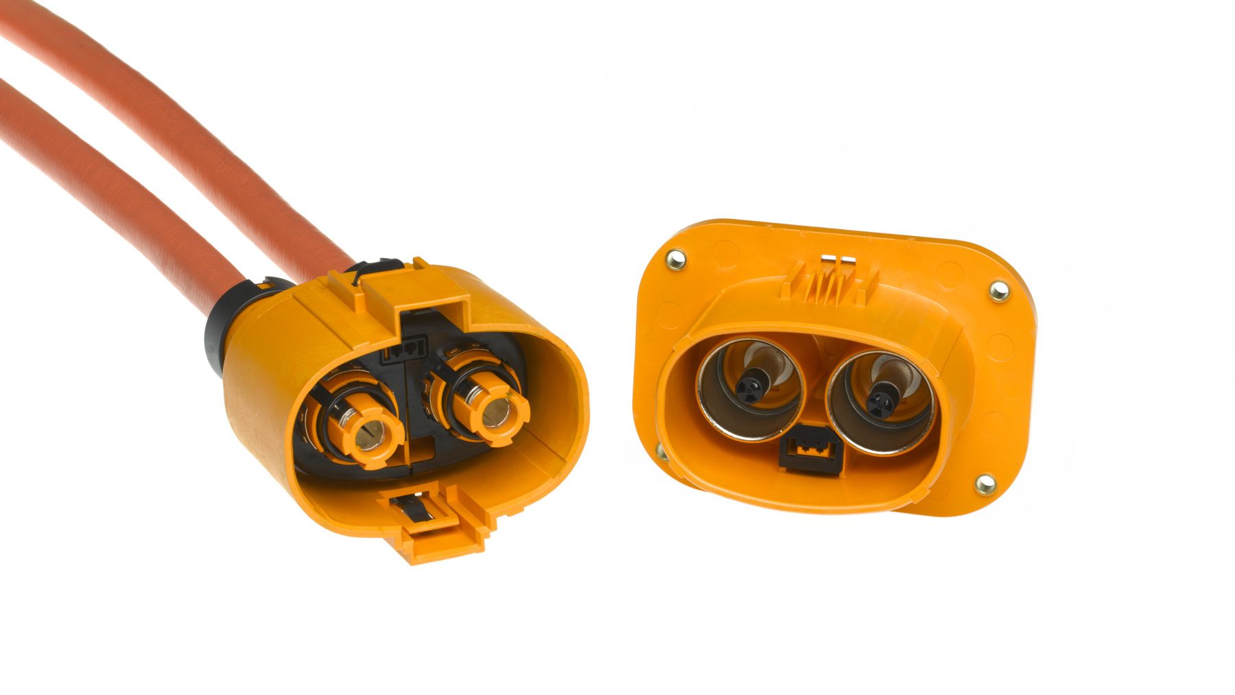
Structural Stability Under Extreme Conditions
Vibration Test
Passes MIL-STD-810G standard vibration test (5-2000Hz, 0.04g²/Hz), with contact displacement <0.1mm.
Uses a 3-point locking structure, requiring an unlocking force >50N (to prevent accidental disconnection).
Waterproof Design
Liquid silicone (0.2mm thick) is injected into housing seams, achieving IP67 certification (immersion in 1m water depth for 30 minutes).
The internal contact area remains dry, with moisture vapor transmission rate <0.01g/m²·day (ASTM E96 standard).
Electrical Performance
Signal Integrity (No Crosstalk):
Sumitomo adopts a dual-layer shielding + ground pin solution, with measured data as follows:
- Shielding Effectiveness:
At 1GHz frequency, the shielding layer reduces external interference to -65dB (industry average -50dB). The internal differential pair shielding layer is 0.1mm thick, using silver-plated copper foil (conductivity ≥95% IACS).
- Grounding Design:
Configures 1 ground pin for every 4 signal pins, with ground contact area 40% larger than signal contacts. Contact resistance after mating is ≤0.5mΩ (USCAR-2 standard requires ≤1.5mΩ).
Stable Impedance (No Drift):
Sumitomo achieves precise control via laser drilling + impedance monitoring:
| Parameter | Control Standard | Measured Tolerance | Industry Comparison |
|---|---|---|---|
| Trace Thickness | 0.035mm±0.002mm | ±0.001mm | ±0.005mm |
| Trace Width | 0.12mm±0.003mm | ±0.002mm | ±0.008mm |
| Impedance Value | 100Ω±5% | ±3% | ±10% |
- Process Details:
Uses UV laser (wavelength 355nm) to engrave FR4 substrate, matching Coefficient of Thermal Expansion (CTE) to 6ppm/℃ (ordinary substrate 10ppm/℃).
Efficient Heat Dissipation (No Overheating):
In high-current scenarios, contact temperature rise exceeding 50°C accelerates oxidation. Sumitomo solves heat dissipation with copper-nickel alloy + thermal slots:
- Material Selection:
Contact base material is CuNi25 (copper-nickel alloy, thermal conductivity 401W/m·K), surface plating is PdAg (palladium-silver alloy, thickness 3μm), with contact resistance stable at 1.2mΩ (at 10A current).
- Heat Dissipation Structure:
Designs 0.2mm wide thermal slots on the connector sidewall, combined with thermal grease (thermal conductivity 5W/m·K), reducing local temperature rise from 78°C to 41°C (ambient 25°C).
High-Frequency Performance (No Attenuation):
Sumitomo's gradual impedance transition design achieves the following performance:
- Insertion Loss:
At 10GHz frequency, single-channel insertion loss ≤0.35dB (industry average 0.5dB). Test conditions: 50Ω system, 25°C.
- Return Loss:
Return loss ≥18dB (industry standard ≥12dB). Verified by S-parameter testing, return loss remains ≥15dB at 30GHz.
- Crosstalk Suppression:
Adjacent channel crosstalk <-45dB (at 10GHz). Uses a four-layer PCB structure with a fully enclosed GND plane in the middle layer, improving isolation by 30%.
Current Handling (No Derating):
Sumitomo's hybrid contact solution achieves dual functionality:
- Power Contact Design:
Uses dual-contact parallel structure (cross-sectional area 2.5mm²), rated current 40A (temperature rise ≤30°C). Surface is hard gold plated (3μm thick), contact pressure 80N±5N.
- Signal Contact Compatibility:
Spacing between power and signal contacts ≥1.5mm, preventing electromagnetic coupling. Tests on a server power module show no signal integrity degradation under 100A transient current.
Manufacturing Process
Mold Engraving:
- Five-Axis EDM Machining
Uses Japanese Mitsubishi EDM machines with 0.02mm diameter electrode wire to engrave 0.35mm pitch contact arrays on copper-tungsten alloy molds. Machining accuracy ±3μm, surface roughness Ra ≤0.4μm.
- Heat Treatment Deformation Compensation
After vacuum quenching (hardness HRC58-62), mold steel (SKD61) undergoes stress relief annealing (550°C×2 hours), reducing thermal deformation from 15μm to 3μm.
Selective Plating:
Contacts require gold plating for oxidation resistance, but cost must be compressed to 40% of traditional methods.
| Process Parameter | Sumitomo Solution | Traditional Solution | Savings Ratio |
|---|---|---|---|
| Plating Thickness | 0.3μm (Pulse Plating) | 1.2μm (Continuous Plating) | 75% |
| Current Density | 20A/dm² (Peak) | 5A/dm² | 3x Efficiency |
| Wastewater Gold Content | <5ppm | 20ppm | 75% Reduction |
- Process Details
Uses titanium basket anode + titanium mesh cathode structure, with pulse current waveform of 10ms on/5ms off. Plating solution contains 0.5g/L nano-silica (particle size 20nm) to improve plating density.
Automated Inspection:
Visual inspection at 300 times per second, rejecting 0.01% of potential defects.
- 3D Coplanarity Inspection
Uses Keyence LS-9030 laser displacement sensor to scan 256 points on the contact surface, building a 3D model. Tolerance band set to ±0.1mm (industry average ±0.3mm).
Measured Data: For a data center connector project, defect detection rate improved from 78% (manual) to 99.97%.
- Micro-Short Detection
High-frequency impedance analyzer (10MHz-3GHz) scans signals between contacts; impedance change >5% indicates a short circuit. False positive rate <0.05% (traditional LCR meter ≥3%).
Material Processing:
The birth of a copper-nickel alloy contact involves 20 process steps.
- Vacuum Melting
Copper (99.99%) + Nickel (25%) melted in a 1200°C vacuum furnace, oxygen content <5ppm. Uses argon gas atomization to produce powder, powder particle size D50=45μm.
- Cold Isostatic Pressing
Powder formed under 200MPa pressure, achieving density of 7.8g/cm³ (traditional hydraulic press only 7.2g/cm³).
- Sintering Process
Sintered at 1100°C for 2 hours in nitrogen atmosphere, shrinkage controlled within 0.3% (industry average ±0.8%).
Environmental Control:
Cleanroom microbial concentration must be <10 CFU/m³.
- Air Circulation System
Three-stage filtration (G4 pre-filter + F8 medium-efficiency + HEPA high-efficiency), air velocity 0.45m/s, 20 air changes per hour. Suspended particle count: ≥0.5μm particles <3520 per m³ (ISO Class 8 standard).
- Electrostatic Protection
Workers wear conductive clothing (surface resistance 1×10^6-1×10^9Ω), workshop humidity maintained at 50%±5%, preventing electrostatic discharge from damaging the plating.
High Reliability
SUMITOMO connectors achieve a failure rate <0.001% over a 10-year lifecycle (industry average 0.01%) through material, structure, and process technologies.
Contacts use gold plating <0.5μm + phosphor bronze base, with contact resistance stable within 10mΩ;
Multi-contact redundant design reduces vibration failure rate below 0.01%;
Fluorine rubber seals with <15% deformation after 100,000 mating cycles meet IP68 protection.
Material Science
Conductive Materials:
- Copper Alloy Substrate:
- Phosphor Bronze (Cu-Sn-P): Contains 8%~10% tin, 0.01%~0.35% phosphorus, tensile strength ≥500MPa, conductivity ≥100% IACS. Used for high-current terminals (e.g., 50A+ power connectors), deformation <0.1mm at 30N contact pressure.
- Beryllium Copper (Cu-Be-C): Beryllium content 1.8%~2.1%, hardness HV 380~420, elastic modulus 130GPa, suitable for high-frequency signal pins (e.g., 5G base station connectors), contact resistance fluctuation <±5% (-40℃~125℃).
- Surface Plating:
- Gold Plating: Thickness 0.3~0.5μm (automotive grade) or 0.1~0.2μm (consumer electronics grade), contact resistance <5mΩ. Complies with ASTM B488 standard, salt spray resistance >1000 hours (5% NaCl solution).
- Palladium-Nickel Alloy (Pd-Ni 80/20): Thickness 0.05~0.1μm, oxidation resistance improved by 30%, used for aerospace connectors (MIL-DTL-5015 standard), oxidation resistance life >15 years at 150°C.
Insulation Materials:
- Base Material Selection:
- Modified PBT (Polybutylene Terephthalate): Contains 30% glass fiber, tensile strength ≥120MPa, Heat Deflection Temperature (HDT) 240°C@1.82MPa. UL94 V-0 certified, CTI (Comparative Tracking Index) ≥600V.
- LCP (Liquid Crystal Polymer): Melting point 280~340°C, dielectric constant 2.9@1GHz, dissipation factor 0.002. Used for high-frequency connectors (e.g., millimeter-wave radar), signal attenuation <0.3dB/m (10GHz).
- Structural Design:
- Multi-layer Injection Molding: Insulator thickness 0.5~1.2mm, embedded metal shielding layer (0.1mm thick), electromagnetic shielding effectiveness (SE) >60dB (1GHz).
- Stress Relief Slot: 0.2mm wide slot at the plug tail reduces stress concentration during mating, increasing lifespan from 5,000 to 10,000 cycles (IEC 60512 standard).
Sealing Materials:
- Rubber Selection:
- Fluorocarbon Rubber (FKM): Fluorine content 66%~70% (Viton™ GR93510), compression set <15% (100°C×24h), oil resistance (ASTM D471) volume swell <5% (100°C×70h).
- Silicone Rubber (VMQ): Hardness Shore A 50±5, tear strength ≥30kN/m, used for medical device connectors (USP Class VI biocompatibility certification).
- Sealing Structure:
- O-ring + Gasket Combination: Compression ratio 25%~30% (after installation), waterproof rating IP68 (1m water depth × 24h).
- Laser Welding Seal: For fiber optic connectors, weld width 0.05mm, helium leak test rate <5×10⁻⁹ mbar·L/s.
- Micro-arc Oxidation (MAO): Generates 20~50μm ceramic layer on aluminum substrate, hardness HV 1200~1500, wear resistance improved 5x (ASTM G65 sandpaper abrasion test).
- Electroless Nickel Plating: Thickness 3~5μm, phosphorus content 8%~12%, corrosion resistance (ASTM B117 salt spray) >1000 hours, used for connector base oxidation protection.
- Plasma Cleaning: Removes surface organics (carbon residue <50ppm), improves plating adhesion (ASTM D4541 cross-cut test >4B).
Environmentally Adaptive Materials:
- Low-Temperature Resistant Formulation:
- Fluorocarbon rubber with 10% carbon black additive, retains >80% tensile strength at -60°C (ASTM D412).
- Silicon-based grease (-70°C~200°C), friction coefficient <0.15 (ASTM D1894).
- High-Temperature Resistant Solution:
- Polyimide (PI) film (25μm thick), long-term use temperature 260°C, dielectric strength >170V/μm.
- Molybdenum-Copper alloy heat spreader (thermal conductivity 150W/m·K), reduces temperature rise by 40% (vs. pure copper).
Material Validation:
- Accelerated Aging Tests:
- Thermal Aging: After 85°C×1000h, contact resistance change rate <10% (IEC 60512).
- Damp Heat Aging: After 85°C/85%RH×1000h, insulation resistance attenuation <20% (MIL-STD-883).
- Chemical Compatibility:
- Exposed to 98% concentrated sulfuric acid (24h), volume change rate <0.5% (ASTM D471).
- Fuel immersion (ASTM D471, 50°C×7 days), hardness change <±5 Shore A.
Validation Standards
Mechanical Durability:
- Mating Cycle Life Test
- Test Method: Uses automated mating/unmating machine (speed 50mm/min), simulating high-frequency operation (e.g., 5000 cycles).
- Criteria:
- Contact resistance change rate ≤20% (initial ≤10mΩ, final ≤12mΩ).
- Mating force attenuation rate ≤15% (initial ≥50N, final ≥42.5N).
- Case Study: An automotive connector's contact resistance increased from 9.8mΩ to 11.5mΩ after 5000 cycles (meets standard).
- Vibration and Shock Tests
- Sinusoidal Vibration (MIL-STD-202G Method 204):
- Frequency range: 10–2000Hz, acceleration 5–20g, 1 hour/axis.
- Failure criteria: Solder joint cracking, pin fatigue fracture.
- Random Vibration (IEC 60068-2-6):
- Power Spectral Density (PSD): 0.01–10g²/Hz, 2 hours duration.
- Data acquisition: Records acceleration and displacement per second, spectrum analysis for resonance points.
- Shock Test (MIL-STD-202G Method 213):
- Half-sine shock, peak acceleration 50g, duration 11ms, 3 times/direction.
- Post-inspection: X-ray scan for solder joint integrity, ultrasonic test for internal cracks.
- Sinusoidal Vibration (MIL-STD-202G Method 204):
Electrical Performance:
- Contact Resistance Verification
- 4-Wire Measurement (Kelvin sensing):
- Equipment: Keysight 34420A micro-ohm meter (accuracy ±0.1μΩ).
- Test conditions: Current 1A, voltage drop ≤10mV (corresponding resistance ≤10mΩ).
- Accelerated Aging:
- After storage at 85°C/85%RH for 1000 hours, contact resistance change rate ≤10%.
- 4-Wire Measurement (Kelvin sensing):
- Insulation and Dielectric Strength
- Insulation Resistance (IEC 60512-3-1):
- Test voltage: 500V DC, duration 60 seconds, resistance ≥1000MΩ.
- Dielectric Strength (UL 486E):
- 1500V AC (peak 2120V) for 1 minute, leakage current ≤5mA.
- Failure Case: A connector failed dielectric test at only 1200V due to insufficient plating thickness (<0.3μm).
- Insulation Resistance (IEC 60512-3-1):
Environmental Compatibility:
- Temperature Cycling Test (IEC 60512-11-12)
- Parameters: -55℃~150℃, temperature change rate 10℃/min, 50 cycles.
- Criteria:
- Seal compression set <15% (ASTM D395).
- PCB Coefficient of Thermal Expansion (CTE) matching error ≤0.5ppm/℃.
- Salt Spray Corrosion (MIL-STD-202G Method 106)
- Conditions: 5% NaCl solution, 35°C spray, 96 hours duration.
- Criteria: Corrosion area ≤5% (ISO 9227).
- Improvement: Upgrading plating to palladium-nickel alloy (0.08μm thick) reduces corrosion rate to below 1%.
- Damp Heat Aging (JEDEC JESD22-A101)
- 85°C/85%RH 1000 hours:
- Weight change rate ≤0.5% (moisture absorption).
- Insulation resistance attenuation ≤20% (initial ≥10GΩ).
- 85°C/85%RH 1000 hours:
Industry Standards:
- MIL-STD-202G
- Application: Aerospace, military electronic equipment.
- Tests:
- Thermal shock (-55℃↔125℃, 500 cycles).
- Vibration fatigue (20g RMS, 2 hours/axis).
- IEC 60512
- Mechanical Tests: Mating life ≥5000 cycles (consumer electronics), ≥10000 cycles (industrial grade).
- Electrical Tests: Contact resistance ≤10mΩ, insulation resistance ≥100MΩ.
- UL 486E
- Terminal Pull-Out Force: ≥100N for 2.5mm² wire (failure threshold 80N).
- Flammability Rating: V-0 (self-extinguishing within 10 seconds, no dripping).
Application Scenarios:
- Automotive BMS Systems
- Test Focus:
- Vibration resistance (-40℃~150℃ engine compartment environment).
- Salt spray protection (coastal salt corrosion).
- Measured Data: A connector's contact resistance increased only 8% after 20g vibration + 96h salt spray.
- Test Focus:
- 5G Base Stations
- High-Frequency Tests:
- Millimeter-wave band (28GHz) signal integrity: Insertion loss ≤0.5dB.
- Temperature drift control: Frequency offset ≤±0.1ppm over -40℃~85℃ range.
- High-Frequency Tests:
- Industrial Robots
- Dynamic Tests:
- Random vibration (5–2000Hz, 5g RMS) simulating robotic arm motion.
- Mating life ≥10,000 cycles (20 cycles/day, lifespan over 14 years).
- Dynamic Tests:
Wide Voltage Range
SUMITOMO connectors achieve full-range coverage from 2.5V to 1000V.
Utilizing PBT/PA66 composite insulation material and copper alloy spring terminals enables 1.5x overvoltage tolerance.
Temperature rise ≤30K at 85°C ambient, meeting ISO 16750-2 and USCAR-2 vibration standards.
Materials and Structure
How is the insulation material selected?
SUMITOMO connectors use a composite base material of PBT (Polybutylene Terephthalate) and PA66 Nylon (Nylon 66), with a specific ratio of PBT 60% + PA66 40%.
This ratio maintains a volume resistivity >1×10¹⁵Ω·cm at high temperatures (85°C) and a tensile strength ≥120MPa.
The material uses injection molding (mold temperature 80-100°C, holding time 15 seconds) to achieve 0.1mm-level wall thickness precision, ensuring the insulation layer is free of air bubble defects.
Terminal Internal Structure Analysis
Copper alloy terminals use phosphor bronze (CuSn10), with plating of silver-nickel alloy (AgNi 80/20), plating thickness 5-10μm.
The contact surface is designed as a dual-wave spring structure, initial pressure 0.9N±0.1N, contact resistance ≤3mΩ.
In mating cycle tests, contact force attenuation is <10% after 50 cycles, mating force curve fluctuation is controlled within ±15%.
How does the sealing structure withstand high-pressure water jets?
Silicone seals use Fluorosilicone Rubber (FVMQ), temperature range -60°C~+230°C, compression set <15% (70°C/22h).
Seal groove depth is 0.3mm, compression ratio 25%±2%, achieving dual IP67/IP69K certification:
- IP67 test: Immersion in 1m water depth for 30 minutes, leakage current <0.1mA
- IP69K test: After 8-10MPa high-pressure water jet (60° spray angle) impact, insulation resistance >10GΩ
Material Performance Comparison Table
| Material Type | Parameter | Test Standard | Measured Data |
|---|---|---|---|
| PBT+PA66 Composite | Volume Resistivity (85°C) | IEC 60112 | 1.2×10¹⁵Ω·cm |
| Phosphor Bronze Terminal | Tensile Strength (ASTM B488) | ASTM B488 | 1150MPa |
| Silver-Nickel Plating | Adhesion (ASTM B571) | ASTM B571 | 3B Grade (No Peeling) |
| Fluorosilicone Rubber Seal | Oil Resistance (ASTM D471) | ASTM D471 | Volume Swell <5% (120°C/72h) |
Structural Design Details
1. Insulation Layer Lamination Process
- Surface Layer: 20% glass fiber reinforced, prevents high-voltage breakdown (power frequency withstand voltage ≥3kV/mm).
- Middle Layer: Added flame retardant (phosphorus compounds), passes UL 94 V-0 (self-extinguishing time <10 seconds).
- Bottom Layer: Uses nano-silica filler, reduces dielectric constant to 3.5 (1MHz).
2. Terminal Plating Thickness Control
- Contact Surface: Silver plating thickness ≥8μm (ensures oxidation resistance).
- Root Area: Nickel plating thickness ≥3μm (prevents copper diffusion).
- Edge Chamfer: R0.1mm radius design, avoids stress concentration causing plating cracks.
3. Sealing Structure Redundancy Design
- Primary Seal: FVMQ material, cord diameter 1.8mm.
- Backup Seal: EPDM sponge gasket (40% compression), blocks moisture vapor penetration.
- Stress Relief: Adds 30° bend at terminal tail, reduces mating stress impact on seal.
Laboratory Test Data
Arc Resistance Test
- Condition: Continuous discharge for 100 hours at 10kV/mm field strength.
- Result: Insulation layer carbonization depth <0.05mm, no through-puncture breakdown.
Thermal Aging Test
- Condition: 125°C/1000 hours + 95%RH.
- Data: Volume resistivity change rate <5%, contact force attenuation <8%.
Mechanical Vibration Test
- Condition: 20-2000Hz/1.5Grms random vibration.
- Result: Seal displacement <0.02mm, terminal contact resistance fluctuation <±5%.
Practical Application Cases
800V EV Battery Pack Connector
- Insulation: PBT+PA66 composite (1.2mm thickness).
- Seal Structure: Dual-layer FVMQ seals + EPDM gasket.
- Validation Data: After 2000 -40℃~+125℃ cycles, leakage current remains <1μA.
Industrial Robot High-Voltage Control Cabinet
- Terminal Plating: Silver-nickel alloy (10μm thickness).
- Vibration Tolerance: 50g half-sine (5-2000Hz) for 3 hours.
- Result: Contact resistance change rate <3%, no plating peeling.
Cross-Industry Applications
Automotive Electronics:
- Traditional Fuel Vehicles:
- 12V Systems: TS series 0.64mm pitch connectors used for ECU (e.g., Bosch MPC5xx series) and sensors (Bosch BMP280 barometric sensor), support -40℃~+125℃ wide temperature range, pass ISO 16750-3 vibration test.
- 48V Mild Hybrid Systems: HX series connectors compatible with Valeo BSG motor controllers, rated current 200A, contact resistance ≤1mΩ, resistance change <5% after 1000 mating cycles.
- Pure Electric Vehicles:
- 800V High-Voltage Platform: HFD-U2 series (1000V DC) used in Tesla Model 3/Y battery packs, supports peak current 300A, passes USCAR-2 High-Voltage Interlock (HVIL) certification, mating life ≥5000 cycles.
- Fast Charging Interface: Compatible with CCS Combo 2 standard (e.g., Porsche Taycan), contact terminals have silver plating thickness ≥10μm, support 200A continuous current, temperature rise ΔT ≤25K (85°C ambient).
- Autonomous Driving Systems:
- LiDAR Connection: NanoPlug™ series (0.4mm pitch) used for Luminar LiDAR and domain controllers (e.g., NVIDIA DRIVE AGX), supports 10Gbps data transfer, EMI shielding effectiveness >60dB (1GHz).
Industrial Automation:
- Robotics Control:
- Collaborative Robots: HX series connectors used for ABB YuMi joint motor power supply, withstand IP67 protection (30 min immersion in 1m water), contact force attenuation <8% after vibration test (5-2000Hz/5Grms).
- Industrial Robotic Arms: HS series compatible with KUKA KR6 R900, rated voltage 600V AC, passes IEC 60529 dust/water protection, operating temperature -40℃~+105℃.
- Power Drive Systems:
- Inverter Connection: HX series used for Siemens SINAMICS G120X, supports 480V three-phase input, surge withstand 10kV/μs (IEC 61000-4-5), mating life ≥10,000 cycles.
- Energy Management:
- Energy Storage Systems: HFD-R series compatible with Tesla Megapack, rated voltage 1500V DC, passes UL 9540 certification, thermal runaway propagation time >40 minutes.
Renewable Energy:
- Photovoltaic Systems:
- String Inverters: HFD-U2 series used for Huawei SUN2000-100KTL, supports 1500V DC input, passes IEC 62790 salt spray test (5% NaCl solution spray 96h), contact impedance change rate <3%.
- Energy Storage Systems:
- Containerized Energy Storage: HS series compatible with CATL EnerC, rated current 400A, withstands salt spray corrosion (ASTM B117/500h), IP54 protection rating.
- Offshore Wind Power:
- Converter Connection: HX series used for Siemens Gamesa SG14-222DD, rated voltage 1000V DC, passes DNV GL certification, operating temperature -40℃~+70℃.
Communications & Data Centers:
- 5G Base Stations:
- RF Connection: NanoPlug™ series used for Huawei AAU 5613, supports 28GHz millimeter-wave band, insertion loss <0.3dB (18GHz bandwidth), return loss >15dB.
- Data Centers:
- High-Speed Backplane Connectors: HS series compatible with NVIDIA DGX A100, supports PCIe 4.0×16, signal integrity test (T-type eye diagram) eye height >80% (56GBaud).
Medical Equipment:
- Surgical Robots:
- Force Feedback Systems: HX series used for da Vinci Xi surgical robot, contact force resolution 0.1N, passes ISO 13485 medical certification, sterilizable (121°C steam autoclave 30 min).
- Imaging Equipment:
- MRI Connection: NanoPlug™ series compatible with GE Signa Premier, non-magnetic materials (ASTM F2503), impedance change rate <0.5% in 3T magnetic field.
Aerospace:
- Avionics:
- Flight Control Systems: HS series used for Boeing 787 flight control computers, withstands MIL-STD-810G vibration (20-2000Hz/20Grms), temperature cycling -55℃~+85℃ (100 cycles).
- Satellite Communications:
- RF Links: NanoPlug™ series used for OneWeb satellite terminals, supports Ku band (12-18GHz), passes MIL-STD-883 electrostatic discharge test.
