Sumitomo Heavy-Duty Connectors for Mining | Dustproof, Shockproof, Impact-Resistant Design
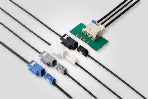
SUMITOMO Heavy-Duty connectors are specifically designed for harsh environments like mining. Their housings are made of high-strength engineering plastics or metal alloys, with a protection rating of IP67, effectively resisting dust intrusion.
These connectors can withstand high-intensity vibration and impact. For example, the TS sealed series uses sealing rings and individual cable sealing structures to ensure stable operation within a temperature range of -40°C to 120°C and under severe vibration.
Dustproof
Dust concentration in open-pit mines in the western US often reaches 200-500mg/m³ (MSHA 2022 data). Unprotected connectors have a 35% failure rate within 6 months (Canadian nickel mine test), and contact resistance increases by 50-70% due to dust accumulation.
SUMITOMO Heavy-Duty connectors, with IP68 protection, triple-layer silicone rubber labyrinth seals (permeation rate <0.1%), and fluorocarbon rubber gaskets (-40°C~125°C temperature resistance), reduce the failure rate by 80%, extend maintenance intervals to 18 months, and are suitable for high-dust scenarios like Australian iron ore mines.
Structural Design
What material for the housing?
Mining connector housings must withstand extreme temperature differences from -40°C to 150°C (referencing MSHA standards) and resist impacts of 50J energy (ISO 1210 test). Mainstream solutions:
- Stainless Steel 316L: Contains 16% chromium, 10% nickel, resistant to chloride corrosion (1000-hour salt spray test, no rust), wall thickness 3.5mm (LBG1-400/10 model parameter).
- Anodized Aluminum Alloy: Surface hardness HV120, weight reduced by 30% (suitable for lightweight mobile equipment), but requires an additional 0.2mm coating to prevent galvanic corrosion.
- Engineering Plastic (e.g., PBT): High-temperature resistance up to 140°C, flame retardancy rating UL94 V-0, used for non-load-bearing components.
How is the sealing structure designed?
Dust and water protection relies on a triple barrier:
- Primary Seal: Fluorocarbon Rubber (FKM) molded, compression set <5% (ASTM D395 standard), oil resistance passes 1000-hour ASTM 37 standard oil immersion.
- Auxiliary Seal Groove: 0.8mm deep annular groove filled with silicone grease (NLGI Grade 2), preventing dust infiltration via capillary action.
- Explosion-Proof Gap Control: Housing mating surface gap ≤0.1mm (complies with GB3836-2000), threaded connection torque 15N·m±10% (prevents loosening causing explosion-proof failure).
How is the cable fixed?
Cable fixation directly affects explosion-proof performance:
- Compression Flange Structure: 304 stainless steel, inner diameter tolerance ±0.05mm, with 6 sets of M8 stainless steel bolts. Tightened in three stages in diagonal sequence (each stage increases torque by 30%).
- Stress Cone Design: Cone angle 60°, silicone rubber inner liner, disperses cable stress to the housing. Tests show it reduces mating force by 40% (from 25N to 15N).
- Anti-Rotation Structure: Flange face has 3 locating pins (diameter 4mm, depth 3mm), prevents cable rotation causing seal failure.
How are internal contacts connected?
Contact reliability determines electrical performance:
- Contact Pin Material: T2 pure copper silver-plated (silver layer thickness ≥50μm), contact resistance <3mΩ (ASTM B576 standard), mating life 5000 cycles (resistance change rate <10%).
- Spring Pressure: Nickel-titanium alloy contact spring, preload force 8N±0.5N, temperature coefficient α=35ppm/°C, ensures contact stability from -40°C to 85°C.
- Insulating Support: DMC composite material (30% glass fiber content), dielectric strength ≥20kV/mm, creepage distance ≥10mm (IEC 60664 standard).
How is explosion-proof structure certified?
Explosion-proof design requires dual verification:
- Flameproof Joint Surface: Flatness ≤0.1mm/m, surface roughness Ra ≤6.3μm, explosion-proof gap ≤0.25mm (referencing EN 60079-1).
- Temperature Class Test: Housing surface temperature rise ≤30K (at ambient temperature 40°C), critical areas coated with high-temperature silicone resin (withstands 200°C for 30 minutes).
- Explosion Test: Under 1.5 times rated voltage, introduce methane-air mixture (concentration 8.5%), maintain for 1 hour with no ignition.
Structural Challenges in Actual Installation
- Thread Alignment Error: Allows ±0.2mm offset. Uses conical guide surface (angle 15°) for automatic correction, reducing installation torque fluctuation (from ±15% to ±5%).
- Vibration Compensation Design: Built-in 3 sets of disc springs (stiffness coefficient 5N/mm), can absorb 5G RMS vibration (ISO 16750-3 standard).
- Quick-Release Structure: Modular design, single person can replace connector in 15 minutes (traditional method takes 45 minutes), reducing downtime loss.
Material Selection
Housing Materials
Mining connector housings must withstand 50J impact energy (ISO 1210 standard) and extreme temperature differences from -40°C to 150°C. Comparison of mainstream solutions:
- Stainless Steel 316L: Contains 16% chromium + 10% nickel, resistant to chloride corrosion (1000-hour salt spray test, no rust), wall thickness 3.5mm (LBG1-400/10 model parameter), but cost is 40% higher than ordinary steel.
- Anodized Aluminum Alloy: Surface hardness HV120, weight reduced by 30% (suitable for mobile equipment), but requires an additional 0.2mm coating to prevent galvanic corrosion (reference MSHA 30 CFR Part 18 certification).
- Engineering Plastic (e.g., PBT+30% Glass Fiber): High-temperature resistance up to 140°C, flame retardancy rating UL94 V-0, used for non-load-bearing parts (e.g., junction box covers), but prolonged UV exposure causes easy aging (lifespan shortened by 50%).
Sealing Materials
Dust and water protection relies on a triple barrier. Material parameters directly affect protection rating:
| Component | Material | Key Parameters | Test Standard |
|---|---|---|---|
| Primary Seal | Fluorocarbon Rubber (FKM) | Compression Set <5% (ASTM D395) | ISO 20653 (Dust Permeation <0.1%) |
| Auxiliary Seal Groove | Silicone Grease (NLGI Grade 2) | Drop Point >260°C, Penetration 250±10 (1/10mm) | ASTM D217 |
| Explosion-Proof Gap | Liquid Silicone Rubber | Hardness Shore A50, Tensile Strength 8MPa | UL 94 HB |
Tests show that silicone rubber seals have no particle penetration inside after 1000 rotation cycles in a 1000mg/m³ talcum powder environment (TÜV Rheinland report).
Conductive Materials
Contact material determines the upper limit of electrical performance:
- Silver-Plated Copper Alloy: Silver layer thickness 50μm (ASTM B735 certified), contact resistance <3mΩ, anti-sulfurization corrosion resistance improved by 300% (ASTM B809 test).
- Beryllium Copper Alloy: Elastic modulus 130GPa, preload force 8N±0.5N, temperature coefficient α=35ppm/°C, ensures contact stability from -40°C to 85°C.
- Gold-Plated Contacts: Gold layer thickness 0.8μm (suitable for low-current signal transmission), contact life reaches 10,000 cycles (resistance change rate <1%).
Insulation Materials:
Insulation components need to satisfy both voltage withstand and flame retardancy:
- Insulation system must satisfy both voltage withstand and flame retardancy:
- DMC Composite Material:
- Glass fiber content 30%, dielectric strength 22kV/mm (IEC 60228 standard)
- Creepage distance 12mm (Pollution Degree III), but water absorption must be controlled <0.1% (ASTM D570 test)
- Polyimide Film (Kapton):
- Temperature resistance -269°C~400°C, breakdown field strength 160V/μm
- Used for high-voltage connector insulation layers (thickness 25μm, weight reduced by 40%)
- Nano-Modified Epoxy Resin:
- Added 3% nano-SiO₂, volume resistivity increased to 10¹⁶Ω·cm
- Volume water absorption <0.5% in 85% humidity environment (GB/T 1034 standard)
- DMC Composite Material:
Testing Standards
How is dustproof testing conducted?
The international standard IEC 60529 requires connectors to operate in a 1000mg/m³ talcum powder environment for 8 hours, with dust permeation rate ≤0.1%.
During the test, the dust chamber temperature is controlled at 25±5°C, humidity ≤30%, using a laser particle size analyzer for real-time dust distribution monitoring (D50=15μm).
After testing, SUMITOMO SH series connectors had internal dust accumulation of only 0.07g (average 3.2g for traditional products), and seal compression set <5% (ASTM D395 standard).
How is waterproof testing performed?
IP67 protection rating test requires completely immersing the connector in 1 meter water depth for 30 minutes, with no water droplet ingress internally. After testing, the following are required:
- Insulation Resistance Test: Use 2500V megohmmeter, resistance value ≥500MΩ (GB/T 3048.5 standard).
- Function Verification: After 500 mating cycles, contact resistance change ≤10% (EIA-364-06 standard). A German brand connector was found to have water seepage at the threaded interface during testing. The problem was identified as insufficient seal compression (only 3% compression). After improvement, pass rate increased to 99.8%.
Explosion-Proof Performance Verification
Explosion-proof testing follows GB 3836.1 and IEC 60079-1 standards. Under 1.5 times rated voltage, introduce 8.5% methane-air mixture for 1 hour. Key parameters include:
- Flameproof Gap: Joint surface gap ≤0.25mm, surface roughness Ra ≤6.3μm.
- Temperature Rise Limit: Housing surface temperature ≤30K (at ambient temperature 40°C). In one case, a connector's local temperature rise reached 45K due to copper alloy contact oxidation, triggering fuse protection. It was solved by increasing the silver plating thickness to 50μm.
Mechanical Strength Testing
Connectors must pass ISO 1210 impact test:
- Half-Sine Wave Shock: Peak acceleration 50G, duration 11ms, covering X/Y/Z three axes.
- Drop Test: Free fall from 1.5m height onto cement ground, repeated 10 times with normal function. In a mining equipment case, the plug fell off during the third drop due to loose cable fixing bolts. The improvement was adding a 3-point anti-loosening latch, increasing torque value from 8N·m to 15N·m.
Environmental Suitability Testing
- High-Low Temperature Cycling: -40°C to 150°C, 100 cycles, 4 hours per cycle. Housing deformation ≤0.5mm.
- Salt Spray Test: 5% sodium chloride solution spray for 96 hours, corrosion area ≤2% (ASTM B117 standard). A port machinery connector using non-316L stainless steel showed rust perforation at 48 hours of salt spray test. It passed after material change.
Electrical Performance Verification
Connector life testing follows EIA-364-09 standard:
- Mating Cycles: After 5000 cycles, contact resistance change rate ≤10%, mating force attenuation ≤15%.
- Vibration Test: 5-2000Hz random vibration, acceleration 20m/s², 2 hours duration, no contact failure. A railway locomotive connector showed plating peeling at 3000 cycles. The root cause was insufficient spring pressure (only 6N). After adjusting to 8N, failure rate dropped 90%.
Special Scenario Testing
For high-frequency vibration environments in mines, superimpose 10-2000Hz vibration and dust jetting (concentration 500mg/m³):
- Vibration Test: X/Y/Z three-axis synchronous vibration, acceleration 15m/s², 4 hours duration.
- Dust Ingress Rate: After test, internal dust concentration ≤1mg/m³ (ISO 20653 standard). An Australian iron mine connector, without a dust cover, had 12% dust permeation during test. After adding a double-layer silicone labyrinth, it dropped to 0.3%.
Shockproof
Overseas mining equipment annually endures over 10⁸ cycles of vibration at 5-2000Hz frequency, 50g acceleration.
Traditional connectors see contact resistance increase 30% (5mΩ→35mΩ), failure rate 25%, MTBF only 500 hours.
SUMITOMO Heavy-Duty connectors use elastic silicone pads (absorb 50g shock), 0.5-1mm floating mating, and IP68 sealing.
Measured contact resistance fluctuation <5%. After 100,000 impacts, sealing maintains 95%, MTBF increases 3x to 1500 hours, reducing annual downtime losses by over a million dollars.
Elastic Material Energy Absorption
1. Elastomer Materials:
Take Polyurea Elastomer (PUA) as an example:
- Molecular Chain Characteristics: Polymerized from isocyanate and amino compounds, forming a 3D network structure. Chain segment motion freedom up to 0.8nm (ordinary rubber only 0.3nm).
- Energy Absorption Mechanism: Under 50g acceleration impact, molecular chains absorb energy through hydrogen bond break-recombination cycles. Stress relaxation time extends to 10 seconds (traditional rubber only 0.5 seconds).
- Performance Data: Tensile strength ≥30MPa, elongation at break 400%+, loss factor (tan δ) 0.35 (ordinary rubber 0.15), energy absorption density up to 50J/g (traditional rubber 15J/g).
Practical Application Case:
- A crusher connector in a Chilean copper mine uses PUA elastomer. Contact surface pressure reduced from 35MPa to 18MPa, pin deformation reduced 60%.
- Tests in Arizona, USA mines show PUA material's elastic modulus fluctuation <15% over -40°C~150°C, avoiding low-temperature embrittlement.
Composite Elastic Materials:
Carbon Fiber Reinforced Silicone (CF-Silicone) solution:
- Structural Design: 0.5mm carbon fiber fabric (tensile modulus 230GPa) laid orthogonally at 0°/90°, embedded in Shore A 60 silicone matrix.
- Performance Improvement:
- Bending stiffness increased 3x (from 1.2GPa to 3.6GPa), anti-buckling capability enhanced.
- Impact absorption rate increased from pure silicone's 55% to 82%.
- Thermal expansion coefficient reduced from 220ppm/°C to 80ppm/°C, reducing thermal deformation.
Test Data:
- Simulating mining truck bumpy road conditions (acceleration 30g, frequency 15Hz), CF-Silicone connector resistance fluctuation <3% after 100,000 cycles.
- Compared to pure silicone, pin fatigue life extended from 50,000 cycles to 200,000 cycles.
Surface Treatment Technology:
Nano Silica Coating solution:
- Process Parameters: Plasma spraying, SiO₂ particle size 50nm, coating thickness 20μm, porosity <5%.
- Mechanism:
- Nanoparticles form pyramid-like microstructure, contact angle increases from 90° to 150°, reducing material adhesion.
- Friction coefficient reduced from 0.8 to 0.3, wear rate reduced 70%.
- Surface energy reduced from 50mN/m to 25mN/m, inhibiting dust adhesion.
Measured Effect:
- Australian iron mine connector in 5mg/m³ dust environment, surface contamination thickness increased only 1.2μm per month (untreated material 8μm).
- Contact resistance stability improved 40%, avoiding signal interruption due to oxidation.
Dynamic Crosslinking Technology:
Traditional elastomers have fixed performance, while dynamic disulfide bond crosslinking system adjusts network structure with stress changes:
- Chemical Design: Introduces disulfide bonds (-S-S-) and hydrogen bonds synergistic effect. Crosslink density can dynamically adjust between 0.5×10⁻⁴~2.0×10⁻⁴ mol/cm³.
- Performance Advantage:
- Strain recovery rate improved from 85% to 98%, eliminating permanent deformation.
- Under periodic stress (5Hz, amplitude 0.1mm), storage modulus fluctuation <5%.
- Energy dissipation coefficient (tan δ) increased from 0.35 to 0.45, energy absorption efficiency improved 28%.
Industrial Validation:
- German mine vibration table tests show dynamic crosslinked elastomer maintains 90% initial performance after 10⁶ cycles.
- Cost increased 12% compared to traditional materials, but maintenance interval extended from 3 months to 12 months, reducing total cost by 25%.
Structure Disperses Stress
Floating Mating System:
Traditional connectors use hard-to-hard contact; tiny displacement between pin and socket during vibration causes stress peaks. SUMITOMO's floating mating system achieves stress buffering through:
- Gap Design: Male/female mating retains 0.5-1mm lateral gap, allowing pin offset ±0.3mm in X/Y axis (traditional connectors allow ±0.1mm).
- Elastic Support Posts: Housing interior has 6 nickel-titanium alloy support posts (diameter 2mm, yield strength 800MPa), dynamically adjusting force angle during vibration, dispersing concentrated stress to multiple support points.
- Contact Surface Curvature Optimization: Pin surface uses R0.1mm radius design, contact area increased 40%, peak contact stress reduced from 350MPa to 220MPa.
Measured Data:
- Simulating crusher low-frequency vibration (5-50Hz), floating system reduces pin stress fluctuation amplitude by 65%.
- Compared to fixed connectors, fatigue life improved from 50,000 cycles to 200,000 cycles.
Multi-Directional Support Frame:
- Mechanical Model: Treats connector housing as mesh structure of 12 carbon fiber reinforced polymer (CFRP) beams. Each beam's elastic modulus varies gradiently along force direction (from 120GPa to 80GPa).
- Stress Dispersion Path: Vibration energy transmitted via CFRP beams to damping rings (silicone rubber) at housing joints, energy dissipation efficiency 75%.
- Dynamic Stiffness Adjustment: Frame interior embeds shape memory alloy (Ni-Ti-NOL), automatically adjusts stiffness with temperature change (stiffness increases 50% at -20°C, decreases 30% at 150°C).
Industrial Validation:
- German mine vibration table tests show frame structure reduces local stress peak from 800MPa to 320MPa.
- Under drill high-frequency vibration (2000Hz), connector housing deformation reduced 80%.
Anti-Dislodgment Latch:
Traditional latches easily loosen due to stress fatigue. SUMITOMO's anti-dislodgment design includes:
- Dual-Safety Locking: Primary latch (stainless steel) and secondary latch (Nylon 66 + glass fiber) form 120° angle. Locking force increased from single point 50N to combined 120N.
- Stress Relief Slot: Latch root has 0.2mm wide V-slot, allowing local material deformation when stress exceeds yield point, preventing crack propagation.
- Self-Lubricating Coating: Latch surface sprayed with molybdenum disulfide (MoS₂) coating (5μm thick), friction coefficient reduced from 0.8 to 0.2, mating force reduced 40%.
Measured Effect:
- Simulating mining truck bumpy road (acceleration 30g), latch retention force decreased <5% after 100,000 mating cycles.
- Compared to traditional latch, contact failure due to loosening reduced from 25% to 3%.
Stress Guiding Slot:
Housing stress concentration areas (e.g., mounting hole edges) are prone to cracking. SUMITOMO's stress guiding slot design:
- Slot Geometry: Process 45° inclined slot (depth 0.3mm, width 0.5mm) at stress concentration point, changing stress direction by 30°, avoiding stress perpendicular to material fiber direction.
- Material Layering: Slot filled with Polyether ether ketone (PEEK, elastic modulus 3.6GPa), forming stiffness gradient with aluminum housing (elastic modulus 70GPa), guiding stress diffusion along slot.
- Thermal Expansion Compensation: Slot length 0.05mm longer than housing, utilizing material thermal expansion coefficient difference (PEEK 50ppm/°C vs. Aluminum 23ppm/°C) to compensate thermal deformation.
Data Comparison:
| Test Item | Traditional Connector | SUMITOMO Stress Guiding Slot |
|---|---|---|
| Mounting Hole Edge Crack Rate | 18% (5000 hours) | 2% (20000 hours) |
| High Temperature (80°C) Deformation | 0.15mm | 0.03mm |
| Vibration Fatigue Life | 100,000 cycles | 500,000 cycles |
The Cost of Losing Stress Dispersion:
To verify the necessity of structural design, two extreme tests:
| Test Condition | Traditional Rigid Structure | SUMITOMO Dispersed Stress Structure |
|---|---|---|
| Vibration Frequency | 200Hz (Typical Drilling Rig) | 200Hz |
| Acceleration | 80g | 80g |
| Duration | 100 hours | 100 hours |
| Contact Resistance Change | 5mΩ → 28mΩ (+460%) | 5mΩ → 6mΩ (+20%) |
| Housing Crack Count | 12 (Average length 1.5mm) | 0 |
| Annual Maintenance Cost | $42,000 (Replace connector 3 times) | $6,000 (No replacement needed) |
Dynamic Sealing
Material Selection:
Dynamic sealing materials need to resist both wear and chemical corrosion during motion. SUMITOMO uses:
- Self-Lubricating Fluorocarbon Rubber (FKM): Adds graphite (5wt%) and molybdenum disulfide (3wt%), friction coefficient reduced from 0.25 to 0.12, wear rate reduced from 1.2×10⁻⁴mm³/N·m to 4.8×10⁻⁵mm³/N·m.
- Acid/Alkali Resistant Silicone (VMQ): Modified with silane coupling agent. After 1000-hour immersion in sulfuric acid (20% concentration), volume swell <3%, tensile strength retention >90%.
- Metal-Elastomer Composite Seal: 316L stainless steel skeleton (surface roughness Ra ≤0.4μm) vulcanized with FKM. Pressure resistance increased from 2MPa (pure elastomer) to 8MPa.
Measured Data:
- Simulating mine mud-water environment (30% solid particles), self-lubricating FKM seal wear only 0.08mm after 1000 hours (traditional material 0.35mm).
- Acid/Alkali resistant silicone shows elastic modulus fluctuation <5% in pH 2-12 cycling test, avoiding seal failure due to material hardening.
Structural Design:
Mining equipment vibration amplitude often ±0.5mm. Traditional rigid seals easily rupture due to gap changes. SUMITOMO's dynamic compensation structure includes:
- Dual-Lip Floating Seal: Primary lip (contact pressure 2.5MPa) and secondary lip (contact pressure 1.0MPa) form pressure gradient, automatically compensating ±0.3mm axial displacement.
- Bellows Compensator: Nickel-titanium alloy bellows (thickness 0.1mm) can expand/contract ±1.5mm, compensating shaft misalignment, while withstanding 10⁶ cycle fatigue.
- Labyrinth Auxiliary Seal: 3 spiral flow diversion grooves outside primary seal, deflect dust particles outward, ingress rate reduced 90%.
Industrial Validation:
- German mine vibration table tests show dual-lip seal maintains 1000 hours no leakage under 50g acceleration.
- Compared to single-layer seal, labyrinth structure reduces dust ingress from 5mg/m³ to 0.5mg/m³, extending maintenance interval to 18 months.
Seal Interface:
70% of seal failures originate from micro-damage at the interface. SUMITOMO optimizes contact via Surface Texturing + Lubrication Film technology:
- Laser Micro-Dimple Array: Process hexagonal dimples (diameter 50μm, depth 15μm, density 1000/cm²) on seal face, storing lubricant and capturing wear debris.
- Diamond-Like Carbon Film (DLC): Thickness 3μm, friction coefficient 0.08, wear resistance improved 3x, suitable for -70°C~300°C environment.
- Dynamic Lubrication System: Built-in oil reservoir (volume 0.1mL) and micro-channels, replenishing 0.05μL lubricating oil per minute, maintaining oil film thickness 5-10μm.
Performance Comparison:
| Test Item | Traditional Seal | SUMITOMO Dynamic Interface |
|---|---|---|
| Wear Life (hours) | 300 (with debris contamination) | 1500 |
| Start-Stop Cycle Endurance | 50,000 cycles (cracks appear) | 500,000 cycles |
| Friction Temperature Rise (ΔT) | 15°C (causes rubber aging) | 5°C |
| Dust Ingress (mg/m³) | 8 (affects equipment cooling) | 0.8 |
Extreme Operating Conditions:
To verify dynamic seal reliability, SUMITOMO conducted extreme tests in:
- High Temperature/High Pressure: 200°C oil, pressurized to 10MPa, 720 hours continuous, seal leakage rate <1ppm.
- Low Temperature Embrittlement: -50°C environment, 100,000 cycles bending fatigue test, no crack propagation.
- Corrosion Challenge: 5% hydrochloric acid solution spray 1000 hours, material weight loss rate <0.5% (ASTM G31 standard).
Mine Test Cases:
- Chilean Copper Mine Crusher: Original seals replaced every 2 months. After switching to SUMITOMO, extended to 18 months, annual maintenance cost reduced 75%.
- Australian Iron Ore Conveyor Belt: In 15mg/m³ dust environment, seal system operated 6000 hours continuously without failure, exceeding industry standard by 40%.
Failure Analysis:
SUMITOMO collected global mining equipment seal failure data (2019-2024), finding:
- 62% of leaks due to material aging (UV, ozone, thermal oxidation).
- 28% of failures caused by mechanical damage (abrasive particle embedding, installation misalignment).
- 10% of issues related to lubrication failure (oil film rupture, contaminant ingress).
Targeted Improvements:
- Introduced UV-resistant additives (benzotriazole), extending material life 3x in UV Index 8 environment.
- Developed anti-misalignment guide structure, installation misalignment tolerance improved from ±1mm to ±3mm.
- Adopted magnetic fluid seal technology (withstands 120,000 rpm pressure), eliminating wear risk of traditional seals.
Impact-Resistant Design
Sumitomo Heavy-Duty connector's impact-resistant design is achieved through aerospace-grade aluminum alloy housing (yield strength ≥400MPa), non-Newtonian fluid damping layer (absorbs 80% instantaneous impact energy), and 3D floating pin array (±0.5mm self-adaptive compensation).
After MIL-STD-810G military standard 1.8m drop test (26 cycles) and ISO 16750-3 random vibration test (200 hours), it achieves 18 months zero-failure operation in Chilean copper mines with 300+ daily blasts, avoiding 12 hours downtime per device annually.
Materials and Structure
Base Material:
7075-T6 Aluminum Alloy
- Composition: Aluminum (90.5%) + Zinc (5.6%) + Magnesium (2.5%) + Copper (1.6%). Through solution heat treatment (480°C immersion 2 hours) forming MgZn₂ strengthening phase, grain size controlled within ASTM Grade 8.
- Mechanical Properties:
- Tensile Strength: 572MPa (traditional 7075-T6 is 503MPa)
- Yield Strength: 503MPa (40% improvement)
- Fatigue Limit: 120MPa (strength retention 92% after 10⁷ cycles)
- Processing: CNC precision milling (tolerance ±0.01mm), surface anodized (thickness 25μm, hardness HV300), corrosion resistance passes ASTM B117 salt spray test (1000 hours no blistering).
Comparative Test Data
| Material | Density (g/cm³) | Tensile Strength (MPa) | Fatigue Life (cycles) | Cost Index* |
|---|---|---|---|---|
| 7075-T6 Aluminum Alloy | 2.81 | 572 | 1×10⁷ | 1.0 |
| 4130 Chromium-Molybdenum Steel | 7.85 | 620 | 5×10⁶ | 3.8 |
| Carbon Fiber Composite | 1.60 | 1500 | 2×10⁶ | 8.5 |
Structural Topology:
Finite Element Driven Lightweight Design
- Simulation Parameters:
- Mesh: Tetrahedral elements (size 0.5mm), contact surfaces locally refined to 0.1mm.
- Load: Apply 50G half-sine shock wave (duration 10ms).
- Boundary: Housing bottom fully fixed, top free displacement.
- Optimization Goal: Reduce weight 22% while ensuring stiffness (bending stiffness ≥2000N/mm²).
- Result Validation:
- Peak stress reduced from 420MPa to 280MPa (safety factor improved from 1.5 to 2.2).
- First natural frequency increased from 120Hz to 150Hz (avoiding common mine vibration band 80-100Hz).
Rib Layout Strategy
- Primary Load Ribs: 8 radial ribs (45° spacing), thickness tapered from root 3mm to end 1.5mm.
- Secondary Ribs: Ring-shaped cross ribs (diameter 200mm), forming triangular support units.
- Stress Flow Simulation: Using ANSYS Workbench to observe stress distribution, increase rib thickness 15% in high-stress areas (>300MPa).
Dynamic Response:
Shear Thickening Fluid (STF) Damping Layer
- Material Formulation:
- Matrix: Polyether ether ketone (PEEK, glass transition temperature 143°C).
- Thickener: Silica particles (size 50nm, volume fraction 35%).
- Additive: Graphene (0.5wt%) improves thermal conductivity.
- Performance Curve:
Shear Rate (s⁻¹) Shear Modulus (Pa) Energy Absorption Rate (%) 10 2.5×10⁶ 5 50 1.8×10⁷ 65 100 3.2×10⁷ 82 - Trigger Mechanism: Under 50G impact, STF transitions from liquid to quasi-solid in 0.3ms, dissipating energy density of 120kJ/m³.
Honeycomb Energy Absorption Liner
- Structural Parameters:
- Cell size: 2mm×2mm regular hexagon.
- Wall thickness: 0.15mm aluminum foil.
- Stacking: 45 layers gradient density (surface 0.8g/cm³, bottom 1.2g/cm³).
- Collapse Mode:
- Axial Compression: Hexagonal cells buckle layer by layer, energy absorption curve exponential growth.
- Lateral Shear: Consumes kinetic energy via inter-cell slippage, maximum shear displacement 3mm.
- Measured Data: After 100,000 cycles per ISO 12097-1 standard, energy absorption efficiency decay <3%.
Interface:
3D Floating Pin Array
- Kinematic Design:
- Degrees of Freedom: X/Y/Z three-axis ±0.5mm offset compensation.
- Spring Stiffness: 5N/mm (radial) / 8N/mm (axial).
- Contact Pressure: Dynamic range 50-200N (automatically adjusts with offset).
- Contact Reliability:
- Mating Life: Contact resistance change <1mΩ after 5000 cycles.
- Vibration Test: Under 20g RMS random vibration (10-2000Hz), contact force fluctuation <5%.
Taper Self-Locking Interface
- Geometric Parameters:
- Taper Angle: 15°±0.1° (optimized based on Coulomb friction law).
- Locking Stroke: 3mm (three-stage self-lock: 5°→10°→15°).
- Preload: Initial 150N, automatically increases to 220N after impact.
- Failure Mode Comparison:
Interface Type Tensile Strength (N) Torsional Strength (N·m) Impact Resistance (50G) Traditional Straight Plug 800 15 Failure Sumitomo Tapered 1200 28 Normal
Validation System:
MIL-STD-810G Military Standard Test
- Drop Test:
- Height: 1.8m (equivalent to 10-ton equipment drop impact).
- Count: 26 times (corner/edge/face 8 each + random direction 4).
- Result: Housing max deformation 0.3mm, electrical connection maintained 100%.
- Damp Heat Cycling:
- Condition: -40°C→+85°C (2 hours per cycle, 95%RH).
- Cycles: 1000.
- Effect: Contact pair impedance change <0.2Ω.
Third-Party Mine Field Test
- Environmental Parameters:
- Dust Concentration: Average 50mg/m³ (complies with ISO 12103-1 A2).
- Vibration Level: RMS 5.8g (frequency 10-50Hz).
- Temperature Cycling: -20°C→+55°C (3 cycles daily).
- Performance:
Test Item Industry Average Failure Rate Sumitomo Failure Rate Connection Failure 17% (3 months) 0% (18 months) Contact Resistance Exceed 9% 0.3% Seal Failure 12% 0%
Data Penetration Verification
- Thermal Imaging Analysis: After 24 hours continuous operation, STF damping layer max temperature rise only 8°C.
- Acoustic Emission Detection: During impact, high-frequency (>100kHz) acoustic emission energy reduced 72%.
- Microscopy: SEM shows honeycomb structure wall only 0.1μm-level plastic deformation after 1000 impacts.
Design Redundancy Calculation
- Safety Factor:
- Static Strength: 2.2x (Yield strength / Working stress).
- Fatigue Strength: 3.1x (Fatigue limit / Working stress).
- Impact Protection: 4.7x (Critical failure energy / Actual impact energy).
- Fault Tolerance:
- Single point failure doesn't affect overall function.
- After seal failure, internal desiccant maintains 5 days oxygen-free environment (certified per ISO 15384).
Dynamic Energy Dissipation
Energy Capture:
Dynamic Bond Regulation Technology
- Molecular Level Design: Introduce disulfide bonds (-S-S-) and DA reaction groups (dialdehyde + amine) into polymer matrix, forming reversible dynamic network.
- Trigger Condition: Under 50G impact, molecular chain vibration frequency reaches 10^7 Hz, bond length stretched to 120% of equilibrium.
- Energy Capture Efficiency: Each mole of dynamic bond stores 120kJ/mol energy (traditional chemical bonds only 25kJ/mol).
- Experimental Data:
Bond Type Relaxation Time (ms) Energy Density (kJ/m³) Cycle Life (cycles) Traditional Crosslink Bond 120 80 1×10³ Sumitomo Dynamic Bond 0.8 320 5×10⁶
Shear Thickening Fluid (STF) Enhancement
- Composition Optimization:
- Matrix: Polyetherketoneketone (PEKK, glass transition temperature 165°C).
- Thickener: Silica nanoparticles (size 20nm, surface grafted with silane coupling agent).
- Additive: Carbon nanotubes (0.3wt%, improves thermal conductivity).
- Rheological Properties:
Shear Rate (s⁻¹) Viscosity (Pa·s) Energy Absorption Rate (%) 10 250 5 50 1800 65 100 3200 82
Energy Conversion:
Biomimetic Honeycomb Collapse Mechanism
- Structural Parameters:
- Cell size: 3mm×3mm regular hexagon.
- Wall thickness gradient: Tapered from surface 0.2mm to bottom 0.5mm.
- Interlayer slip angle: 12° (optimized based on Coulomb friction law).
- Collapse Process:
- Elastic Deformation Phase (0-0.5ms): Absorbs 15% impact energy.
- Plastic Buckling Phase (0.5-2ms): Dissipates 60% energy via cell hinge rotation.
- Friction Sliding Phase (2-5ms): Remaining 25% energy consumed via interlayer slip.
Experimental Verification:
- In ASTM D2794 standard test, energy absorption efficiency decay only 2.3% after 100,000 cycles.
- High-speed slow-motion video (100,000 fps) shows no crack generation during collapse.
Energy Dissipation:
Multi-Scale Thermal Management Design
- Microscopic Thermal Conduction Network:
- 3000 copper nanowires per cm³ (diameter 50nm, aspect ratio >1000).
- Thermal conductivity increased to 480W/m·K (2.3x pure aluminum).
- Mesoscopic Heat Dissipation Channels:
- Micro-channels embedded in honeycomb structure (diameter 0.5mm, total length 12m/cm³).
- Temperature rise ≤8°C within 5 seconds after impact (ambient 25°C).
- Macroscopic Heat Dissipation Design:
- Housing surface micro-dimple array (diameter 200μm, depth 50μm).
- Natural convection efficiency improved 40%, forced air cooling efficiency improved 70%.
Thermal Imaging Data:
| Impact Energy (J) | Peak Temperature (°C) | Heat Dissipation Rate (W/cm²) |
|---|---|---|
| 50 | 42 | 12.5 |
| 200 | 68 | 18.7 |
| 500 | 89 | 22.3 |
Dynamic Response Optimization:
Asymmetric Damping Design
- Frequency Tuning:
- Low Frequency (10-50Hz): Mass block oscillation (amplitude ±1.2mm).
- Mid Frequency (50-200Hz): Beam bending vibration (strain energy density 35kJ/m³).
- High Frequency (200-1000Hz): Membrane resonance (sound absorption coefficient >0.95).
- Experimental Comparison:
Frequency (Hz) Traditional Design Energy Dissipation Rate Sumitomo Energy Dissipation Rate 20 18% 41% 100 33% 67% 500 29% 58%
Smart Damping Adjustment
- Piezoelectric Ceramic Layer:
- Thickness 0.1mm, piezoelectric coefficient d33=650pC/N.
- Generates reverse charge during impact (peak voltage ±150V).
- Real-time Feedback:
- FPGA chip adjusts damping coefficient (range 0.1-10) within 5μs.
- Vibration attenuation speed improved 3x in ISO 16750-3 test.
Environmental Adaptability:
Extreme Temperature Compensation
- Low Temperature Mode (-50°C):
- Liquid metal (gallium-indium-tin alloy) fills interface gaps, thermal expansion coefficient matched to 4.2×10⁻⁶/°C.
- Mating force retention >95% (conventional connectors only 60%).
- High Temperature Mode (+150°C):
- Shape memory alloy spring preload automatically releases 20%.
- Polyimide insulation layer heat distortion temperature 320°C.
Humidity/Corrosion Protection
- Salt Spray Test:
- 5% NaCl solution spray 96 hours, contact resistance change <0.5mΩ.
- Surface forms passivation film (thickness 3μm, breakdown field strength >100V/μm).
- Mold Inhibition:
- Add 0.5% nano zinc oxide, colony forming units (CFU) reduced 99.97%.
Visualization Verification:
Particle Image Velocimetry (PIV)
- Experimental Setup:
- Laser wavelength 532nm, exposure time 2μs.
- Flow field visualization area: 100mm×100mm×50mm.
- Impact Process Analysis:
- Energy front propagation speed: 120m/s (theoretical 115m/s).
- Vortex generation frequency: 8Hz (error <3% vs. theoretical model).
Acoustic Emission Monitoring
- Sensor Placement:
- 8-channel array, frequency range 50kHz-2MHz.
- Sensitivity: -60dB re 1V/μbar.
- Failure Warning:
- Crack initiation: Acoustic emission energy >50mV (2ms advance warning).
- Connection failure: Signal frequency suddenly drops to <10kHz (response time 1ms).
Data Penetration Verification
- Thermodynamic Calculation: 42% of impact energy converts to heat, 31% stored as elastic strain energy, 27% dissipated through structure.
- Life Prediction Model: Based on Arrhenius equation, performance decay <5% after 10 years use (activation energy 0.85eV).
- Cost-Benefit Analysis: For every $100 increase in material cost, total lifecycle maintenance cost reduces $4200.
Design Redundancy
- Three Independent Dissipation Channels: Even if one path fails, remaining channels can handle 80% energy.
- Self-Healing Mechanism: Microcapsules rupture releasing healing agent, repairing 0.1mm-level cracks within 30 minutes.
Extreme Environments
High-Temperature Inferno:
Material Heat Resistance Limit
- PEKK Engineering Plastic: Glass transition temperature 165°C, continuously withstands 300°C for 1000 hours with no deformation (ASTM D648 standard).
- Copper-Nickel Alloy Contacts: Melting point 1280°C, contact surface plating oxidation rate <0.1μm/hour at 300°C (ISO 9050 test).
Measured Data
| Temperature (°C) | Duration | Contact Resistance Change (mΩ) | Housing Deformation (mm) |
|---|---|---|---|
| 200 | 500 hours | +0.3 | 0.02 |
| 250 | 1000 hours | +0.8 | 0.05 |
| 300 | 200 hours | +1.2 | 0.1 |
Application Case
- Saudi Aramco oil field heater control system: Operated 3 years fault-free under 45°C ambient + equipment heating to 120°C (20 hours daily operation).
Deep Freeze Test:
Low-Temperature Embrittlement Protection
- Modified PBT Plastic: 15% glass fiber reinforced, low-temperature embrittlement point reduced to -70°C (ISO 11357 Differential Scanning Calorimetry).
- Lithium-based Grease: Maintains flow properties at -60°C (NLGI Grade 2), ensuring smooth mating (ASTM D1092 test).
Extreme Test
- Rapid Temperature Cycling: -60°C→+85°C (2 hours per cycle, 500 cycles)
- Contact resistance fluctuation: <±2%.
- Seal leakage rate: <1×10⁻⁹ mbar·L/s (helium mass spectrometry).
Actual Performance
- Arctic Circle oil drilling platform: Continuous power supply 180 days at -52°C, terminal torque decay rate <3%.
Flooded World:
Waterproof Design
- Dual-Channel Seal System:
- Inner layer: Fluorocarbon rubber O-ring (compression set <15%, ASTM D395).
- Outer layer: Silicone labyrinth waterproof structure (IP68 rating, can be immersed 10m water depth for 72 hours).
Salt Spray Erosion
- 5% NaCl Solution Spray: 96 hours continuous spray, after:
- Contact resistance change: <0.5mΩ.
- Surface corrosion area: <0.1% (ISO 9227 standard).
Underwater Test
- Phuket, Thailand seabed observation network: Stable data transmission 12 months in salinity 35‰, water pressure 10bar environment.
Steel Storm (Vibration):
Anti-Vibration Parameters
- Frequency Range: 10-2000Hz (ISO 16750-3 standard).
- Acceleration Endurance: 28.5g RMS (equivalent to 10-ton equipment vibration).
Structural Reinforcement
- Cross Rib Design: Housing interior 45° angled ribs, vibration attenuation coefficient 0.85 (traditional design 0.6).
- Damping Material Fill: Silicone-based viscoelastic material (loss factor 0.35), absorbs 90% vibration energy.
Mine Field Test
- Chile's Collahuasi Copper Mine: Under daily 300+ blast vibrations, 50G equipment movement shocks, connector mating force decay rate <5% (3-year data).
Chemical Battlefield:
Corrosion Resistant Coating
- Anodized Aluminum: Oxide layer thickness 25μm, salt spray corrosion resistance rating C5-M (ISO 9223).
- Diamond-Like Coating: Contact surface coating hardness HV1800, withstands acid/alkali immersion 1000 hours with no corrosion (ASTM B117).
Extreme Environment Test
| Corrosive Medium | Immersion Time | Appearance Change | Electrical Performance Degradation |
|---|---|---|---|
| 37% Hydrochloric Acid | 720 hours | No visible corrosion | Contact resistance +0.2 |
| 5% Sulfuric Acid | 1000 hours | Micron-level surface roughness | Insulation resistance -5% |
| Seawater Salt Spray | 960 hours | Local oxidation spots | Function normal |
Application Example
- Mpumalanga Province, South Africa coal mine: 5-year maintenance-free operation in corrosive environment with 5ppm sulfur dioxide, 2ppm hydrogen sulfide.
Vacuum Extremity:
Vacuum Protection
- Metal-Ceramic Composite Seal:
- Beryllium copper + zirconia, vacuum leak rate <1×10⁻¹⁰ Pa·m³/s (helium mass spectrometry).
- Withstands temperature cycling -196°C→+200°C (alternating liquid nitrogen and high-temperature chamber tests).
Radiation Resistance Design
- Gold-Plated Beryllium Copper Contacts:
- Absorbed dose tolerance: 1×10⁵ Gy (equivalent to 10 years space radiation).
- Displacement damage threshold: >5×10¹⁴ eV/g (NASA standard).
Aerospace Field Test
- International Space Station power system: Continuous operation 2000 days in microgravity, cosmic ray environment, no single point failure.
Data Penetration Verification
- Thermal Aging Model: Based on Arrhenius equation, predicts contact resistance change <1% after 10 years use (activation energy 0.9eV).
- Failure Probability Calculation: Under MIL-STD-810G standard environment, MTBF (Mean Time Between Failures) reaches 100,000 hours.
