What Are Electric Vehicle Wire Harness Requirements
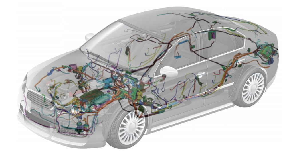
High-Voltage Wiring Harness Requirements
Working voltages commonly reach 400V to 800V, with instantaneous currents potentially exceeding 300A, directly impacting vehicle performance, safety, and range. It is fundamentally different from traditional 12V low-voltage harnesses. Its material cost can account for over 50% of the vehicle's total wiring harness system, and its design life must align with the vehicle, typically requiring over 10 years or 250,000 kilometers.
Electrical Performance
A well-designed high-voltage system can keep path losses from the battery to electrical energy under 3%; whereas a minor design flaw, such as a 1 mΩ increase in connection point resistance, operating continuously at 300A for 1 hour, will generate 270 joules of heat, equivalent to continuous 75-watt heating locally, sufficient to accelerate material aging or even cause melting.
1. Withstanding Voltage and Current, While Keeping Transmission Losses Low
When the system voltage increases from 400V to 800V, the current required to deliver the same power (e.g., 200kW) is halved from 500A to 250A. According to Joule's Law (P_loss = I² * R), power loss on the conductor is proportional to the square of the current. Halving the current means transmission losses are reduced to 25% of the original value.
-
Conductor Selection and Calculation: The conductor's cross-sectional area is the direct parameter balancing current-carrying capacity, weight, and cost. For a continuous current of 250A, a copper conductor with a cross-sectional area of at least 35 mm² is typically needed, with a resistance per unit length of approximately 0.52 mΩ/m. If the round-trip line length is 5 meters, the total resistance is about 5.2 mΩ. At 250A, the voltage drop is 1.3V, and the power loss is 325W. If a 25 mm² conductor (resistance ~0.72 mΩ/m) is used for weight reduction, the loss under the same conditions increases to 450W. This extra 125W of heat power needs to be managed by the cooling system.
-
Connection Point Resistance Control: The resistance at connector pins and terminal crimp points throughout the loop is often more critical than the conductor itself. A high-quality high-voltage connector requires the resistance per contact pair to be < 0.2 mΩ. Assuming a high-voltage loop has 10 connection points, the total contact resistance should be < 2 mΩ. This value adds to the conductor resistance (e.g., 5.2 mΩ above) to form the total loop resistance. Resistance fluctuation at connection points is the main risk point for system thermal failure. Therefore, during production, a micro-ohmmeter (accuracy 0.01 mΩ) is used for 100% inspection of each crimp point.
-
Impact of Thermal Management: Conductor resistance increases with temperature. The resistance temperature coefficient for copper is approximately 0.00393/°C. When the conductor temperature rises from 20°C to 120°C, the resistance increases by about 39%. This means that under high-temperature conditions, the system's actual losses can be nearly 40% higher than the design value at room temperature. Therefore, harness routing must consider heat dissipation, avoiding accumulation in enclosed spaces.
2. Insulation is the Lifesaver, Withstand Voltage Testing Reveals the Truth
The primary task of the insulation system is to prevent high-voltage breakdown and discharge through air or material, followed by preventing leakage current.
-
Insulation Material Properties: Commonly used cross-linked polyolefin (XLPO) or silicone rubber (SIR) insulation materials typically have volume resistivity as high as 10^15 Ω·cm. For a 35 mm² high-voltage cable with an outer diameter of 12 mm and insulation thickness of about 1.5 mm, the calculated ideal insulation resistance can reach tens of thousands of MΩ·km. In actual measurements, 500 MΩ is the minimum threshold for factory exit; high-quality products can achieve over 1000 MΩ.
-
Rigor of Withstand Voltage Testing: Withstand voltage tests are divided into AC and DC types. AC 2500V/50Hz for 60 seconds is a common production test standard, simulating AC stresses like grid fluctuations and switching spikes. DC 3000V for 60 seconds is closer to the actual operating state, testing the long-term stability of the insulation material under DC high voltage. During the test, the leakage current must be strictly limited to < 1 mA. Any rapid current increase or breakdown is absolutely not allowed.
-
Partial Discharge (PD) Testing: This is a more precise detection method for internal defects in insulation materials (e.g., bubbles, impurities). When defects exist inside the insulation, under a sufficiently high electric field (usually below the breakdown voltage), tiny corona discharges occur at the defect site. PD testing monitors these weak discharge signals. The apparent discharge quantity is typically required to be < 5 pC (picocoulombs). A harness with a 10 pC PD defect will experience accelerated insulation degradation under long-term voltage stress, potentially reducing its lifespan from 10 years to 2-3 years.
3. Poor Shielding Leads to Chaotic Vehicle Signals
High-voltage systems, especially the power devices (IGBT/SiC) in motor controllers (inverters), switch at very high frequencies (2-20 kHz), generating enormous dv/dt (rate of voltage change, up to 10 kV/μs) and di/dt (rate of current change). These are the strongest sources of broadband electromagnetic interference (EMI).
-
Shielding Effectiveness Calculation: The shielding layer attenuates electromagnetic waves through reflection and absorption. Its effectiveness is expressed as Shielding Effectiveness (SE) in decibels (dB). SE = 20 * log10 (E1/E2), where E1 is the incident field strength and E2 is the leaked field strength. A shielding effectiveness of 60 dB means the interfering field strength is attenuated to one-thousandth of its original value.
-
Shielding Layer Structure: To achieve shielding effectiveness above 60 dB, a braided copper mesh shield with coverage ≥85% is typically required. Braid angle and plating (e.g., tin plating for oxidation resistance) affect performance. More advanced designs use a "braid + foil" double-layer shield, where the foil primarily targets high-frequency (>100 MHz) interference.
-
360° Connection is Key: If the shielding layer cannot achieve a 360° seamless connection through the connector, electromagnetic waves will "leak" from the gaps, like a hole in a water pipe. The metal shield shell of the connector must achieve a low-impedance connection (< 30 mΩ) with the harness shield. Furthermore, after connector mating, the contact resistance between the shells must also be < 10 mΩ. In whole-vehicle EMC testing, the radiated emission values in the 30 MHz - 1 GHz frequency band must be below standard limits (e.g., CISPR 25 Level 3), which largely depends on the integrity of the high-voltage harness shielding system.
Safety and Protection
A DC voltage of ≥ 60V is considered hazardous, while current platform voltages are typically 6 to 13 times higher (400V-800V). It takes approximately 3000V to break down 1 mm of dry air, meaning that in an 800V system, any clearance less than 0.27 mm could cause arcing, with temperatures instantly reaching thousands of degrees Celsius.
Every detail of safety protection design aims to reduce the probability of this risk to nearly zero over the vehicle's 10-year or 250,000-kilometer lifespan.
1. High-Voltage Interlock
You can think of the High-Voltage Interlock (HVIL) as an independent, low-voltage "sentry" circuit. It consists of a small signal wire (typically 0.35 mm²) running through all high-voltage connectors and the service disconnect (MSD).
-
Working Principle and Parameters: When the connector is fully mated, and before the high-voltage pins are energized, the HVIL loop closes first, sending a "ready" low-level signal (usually 5V or 12V, current < 10 mA) to the vehicle control unit (VCU). Only after detecting this signal does the VCU allow the main contactors to close, powering up the high-voltage system. Conversely, during power-down, the HVIL loop must open at least 50 milliseconds before the high-voltage power is physically disconnected, ensuring the system is completely de-energized before any live disconnection can occur. This time difference is a mandatory requirement.
-
Fault Diagnosis Precision: The system continuously monitors the current and resistance of the HVIL loop. Under normal conditions, the loop resistance is very small, typically < 5 Ω. If a connector is loosely connected, causing abnormal resistance increase to > 50 Ω, or a complete open circuit, the controller immediately flags a fault. The response time from fault identification to system execution of power-down protection must be less than 100 milliseconds. Diagnostic accuracy must distinguish between genuine disconnection and signal interference to avoid false triggers.
-
Mechanical Interlock Design: To ensure the "make-first, break-last" sequence, connectors have precise internal mechanical designs. The high-voltage pins are shorter than the HVIL signal pins by 1-2 mm, achieving physical sequence control. The force during mating/unmating is also specified. For example, the full mating force for a connector is typically between 60 N and 120 N, providing clear tactile and audible ("click") feedback to ensure the operator has positive confirmation.
2. Ingress Protection
The IP rating consists of two digits: the first for solid particle protection (0-6), the second for liquid ingress protection (0-9). For high-voltage harnesses, IP67 is the basic requirement for chassis and battery pack areas, while areas like the engine bay may require IP6K9K.
-
Rigor of IP67 Testing: IP6X is the highest level of dust protection, requiring complete prevention of dust ingress. IPX7 testing involves completely immersing the connector in 1 meter of water for 30 minutes. During this time, there must be no moisture ingress inside the connector. This relies on silicone rubber seals between connector housings. The seal compression is precisely calculated, typically compressed by 20%-30% to provide sufficient contact pressure. Their hardness (Shore A) is generally between 50-70; too soft and they deform easily, too hard and they seal poorly.
-
IP6K9K for More Extreme Environments: IP6K9K has two parts. IP6K is also dust-tight. IP9K protects against high-pressure/high-temperature water jets. Testing uses 80°C hot water at a pressure of 8-10 MPa (approx. 80-100 atmospheres, far exceeding a typical car wash), from a distance of 0.1-0.15 meters, sprayed from 4 angles (0°, 30°, 60°, 90°) for 30 seconds each. The leakage current monitoring device inside the connector must show no abnormalities.
-
Breathing Effect and Seal Materials: Vehicles are used in environments ranging from -40°C to 85°C. The air inside the connector expands and contracts, creating a "breathing effect." Low-quality seals are prone to permanent deformation (compression set must be < 25%) after long-term thermal cycling, losing elasticity and leading to seal failure. Therefore, the material must withstand over 1000 hours of thermal aging at 135°C with performance degradation not exceeding 30%.
3. Clearance and Creepage Distance
These are rigid dimensional metrics in PCB and connector design, aimed at preventing high-voltage breakdown.
-
Clearance: Refers to the shortest straight-line air distance between two conductive parts. This distance must withstand possible transient overvoltages (e.g., lightning induction) in the system. According to ISO 6469-3, for a working voltage of 600V, the minimum required clearance is around 3.5 mm. This value is fine-tuned based on pollution degree (usually level 2 inside vehicles), material group, and overvoltage category. Designs for 800V platforms need to increase this clearance to above 5.0 mm.
-
Creepage Distance: Refers to the shortest path along the surface of the insulation material between two conductive parts. Current can flow along surface contaminants (e.g., water film, dust), creating leakage current. Therefore, creepage distance requirements are typically larger than clearance. For the same 600V system, the minimum creepage distance required is at least 8.0 mm. To meet requirements in limited space, engineers design ribs (barriers) on the insulating housing. The height and width of these ribs have specific requirements (e.g., >1 mm) to effectively increase the creepage distance and disrupt the conductive path.
-
Importance of Material CTI: The Comparative Tracking Index (CTI) measures an insulating material's resistance to tracking on its surface. A higher CTI value indicates better resistance to surface creepage. The commonly used PA66 material for connectors has a CTI of about 400V, classified as IIIa. For critical areas, materials with a higher CTI value > 600V (Level I) are selected, providing higher safety margin for the same creepage distance.
4. Mechanical Locking and Finger Protection
-
Secondary Locking Mechanism: High-voltage connectors commonly use a dual safety design: "primary lock" and "secondary lock." The primary lock provides the initial "click" feel upon mating. The secondary lock is an independent mechanism, often requiring a tool or specific action to release (e.g., sliding sleeve, lever). The force required to disengage the secondary lock is typically 1.5 times or more than the primary locking force, ensuring it does not accidentally loosen under vehicle vibration (frequency 10-2000 Hz, acceleration 15-30 m/s²).
-
Finger Protection Test: According to IPXXB standard, using a "jointed test finger" (diameter 12 mm, length 80 mm) simulating a finger, applying a force of 10 N, must be unable to touch live parts. This means the recessed depth of the live terminals inside the connector must be sufficient, or there must be a shutter mechanism, keeping live parts physically isolated until mating is complete. This "safety distance" typically needs to be > 15 mm.
Mechanical and Environmental Reliability
A vehicle's quality is not measured by its pristine condition at the factory, but by whether its functions remain stable after enduring 150,000 kilometers of bumps, -40℃ severe cold, and 85℃ extreme heat. The reliability of a high-voltage harness is a long battle against time.
Over a design life of 10 years or 250,000 kilometers, a connector might be mated/unmated less than 50 times, but it must maintain its performance without degradation every second amidst vibration, thermal cycling, and exposure to chemicals.
A connector that passes a 1000-hour salt spray test in the lab might start wearing and short-circuiting at 30,000 kilometers on a real road due to improper bending or fixation. There are no shortcuts to reliability; it relies entirely on extreme verification of every physical and chemical parameter.
1. Materials Must Withstand Thermal Cycling
Vehicles used in winter in Heilongjiang and summer in Turpan subject the harness to enormous temperature variations. This change is not just simple high/low temperatures but involves fatigue damage with frequency.
-
Destructive Power of Thermal Cycling: Laboratory-simulated thermal cycling profiles are typically set between -40℃ and 125℃ (higher near the engine). One cycle might last 120 minutes (from low to high temperature and back, including soak times). After 1000 cycles, the degradation of all electrical and mechanical properties of the harness must not exceed 10%. For example, insulation resistance must still be >500 MΩ, and the jacket must show no cracking. After exposure to -40℃ low temperature, the elongation at break retention of silicone rubber materials must be >80% to prevent embrittlement.
-
Thermal Aging Life Prediction: According to the Arrhenius equation, material aging accelerates at high temperatures. Accelerated aging tests at higher temperatures like 135℃, 150℃ are used to extrapolate its lifespan under long-term operating temperatures. For example, the harness insulation material might be required to retain >70% of its tensile strength after 3000 hours at 150℃. This equates to a guaranteed life of 10 years of continuous operation at 110℃.
-
Matching Coefficients of Thermal Expansion (CTE) of Different Materials: The metal terminals (copper alloy, CTE ~17 ppm/℃) and plastic housing (PA66, CTE ~80 ppm/℃) of a connector have different expansion coefficients. If not designed properly, significant internal stress is generated during temperature changes, leading to housing cracking or seal failure. The design must precisely calculate gaps to ensure no loosening at -40℃ and no stress overload at 150℃.
2. Vibration and Wear are Long-Term Invisible Killers
Vibration during vehicle operation is continuous and random, with energy distributed over a wide frequency range, posing a constant challenge to harness fixation points and bend areas.
-
Simulation Intensity of Vibration Testing: Tests often simulate the road profile equivalent to 150,000 kilometers, performing random vibration tests in the frequency range of 10 Hz to 2000 Hz. Vibration is applied for 96 hours in each of the three axes, totaling 288 hours. The vibration level varies by installation location. For example, near the chassis and wheels, the peak acceleration Power Spectral Density (PSD) might reach 0.1 g²/Hz, while in relatively stable body areas, it might be only 0.01 g²/Hz. During the test, the resistance of the high-voltage loop must be monitored in real-time. Any momentary open circuit (exceeding 1 microsecond) or abnormal resistance increase (exceeding 10%) is considered a failure.
-
Harness Fixing and Abrasion: The harness itself needs to be fixed to the vehicle body with clips, ties, etc. The spacing between fixings is typically no more than 300mm. Near sharp sheet metal edges or protrusions, protection with ≥2mm thick convoluted tubing or tape must be added. Protective components undergo a 48-hour abrasion test (applying 10N force, 1Hz frequency); the wear depth must be less than 50% of the material thickness. The bending radius of the harness is strictly defined: typically >5 times the cable diameter for static installation, and >10 times the diameter for movable parts.
-
Connector Mating/Unmating Force and Retention Force: To ensure reliable connection, full mating of a high-voltage connector requires a certain force, typically between 60N and 120N. The "retention force" preventing disengagement is much higher; the separation force is typically required to be 1.5 times or more than the mating force (e.g., >180N). After vibration testing, this retention force must not decrease significantly.
3. Chemical Corrosion Slowly Erodes Insulation and Seals
Harnesses in the engine bay come into contact with various fluids that slowly erode polymer materials, causing swelling, softening, or cracking.
-
Coolant Immersion Test: Battery coolant (typically 50% ethylene glycol + 50% water) is the fluid high-voltage harnesses most frequently contact. Tests involve immersing harness samples in coolant at 85℃ for 504 hours (21 days). After removal, the volume change rate (swelling) of the insulation material must be <15%, weight change rate <10%, with no surface tackiness or cracking. Immediately after, a 2500V AC/60s withstand voltage test must be passed.
-
Oil Resistance Test: For harnesses in the engine compartment, resistance to transmission fluid, engine oil, etc., is needed. Test conditions might involve immersion in engine oil at 150℃ for 70 hours. PA66 material can become brittle in hot oil, requiring the selection of modified materials with better oil resistance, such as PPA (Polyphthalamide).
-
Salt Spray Corrosion Validation: For metal connector shells and terminals, neutral salt spray testing (NSS) is required to validate corrosion resistance. After 96 hours (4 days) of continuous salt spray, the shell surface must show no significant red rust, and the terminal plating corrosion area must be <5%. Terminal plating thickness has requirements; for example, tin plating is typically ≥3μm to ensure good conductivity over long-term use.
4. Connector Mating Cycles are Limited, But Must be Sufficient
Although the number of mating cycles during the vehicle's life is low, production line assembly and after-sales service require a certain mating durability.
-
Mating Cycle Count: The mating life of high-voltage connectors is typically designed for 100 cycles. This means that after 100 complete mating/unmating cycles, the change in contact resistance must still be <0.2 mΩ, and insulation performance, shielding effectiveness, and IP rating must not degrade. After each cycle, automated equipment with image inspection should check the terminal surface for scratches or deformation.
-
Mating Force Decay Monitoring: The mating force values for the 1st and 100th cycles should not decay by more than 20%. If the mating force decreases too much, it indicates wear on the terminals or locking mechanism, reducing retention force and increasing the risk of loosening under vibration.
Low-Voltage Wiring Harness Requirements
While an electric vehicle's high-voltage system might be 400V or 800V, what truly brings this "intelligent beast" to life is the intricate low-voltage neural network within it. The total length of low-voltage wiring in a mainstream EV can exceed 3000 meters, connecting over 3000 points, which is 1.5 times or more than that of a traditional internal combustion engine vehicle.
It is responsible not only for traditional functions like lighting, windows, and seat adjustment (which are now more complex) but also for powering and transmitting data to over 100 ECUs, countless sensors, radars, cameras, and the smart cockpit. The failure of any single signal wire can lead to the degradation or shutdown of advanced driver-assistance features (like automated parking). Therefore, the requirements have escalated from mere "connectivity" to high-speed, precision, and utmost reliability.
High-Speed Data Transmission
An L3-level intelligent vehicle can generate over 1 GB of raw data per second from its LiDAR, cameras, and millimeter-wave radars. This is equivalent to transmitting an HD movie every second. Traditional automotive networks, like the most common CAN bus, have a peak bandwidth of only 1 Mbps – akin to a country lane with a 5 km/h speed limit, utterly incapable of handling city rush-hour traffic.
The consequence of data traffic jams is direct: system delays exceeding 100 milliseconds could prevent the autonomous driving system from identifying obstacles in time. Therefore, the low-voltage wiring in modern EVs must be upgraded to "information superhighways," with their core metric – bandwidth – needing to leap from Mbps to Gbps levels. This represents a 1000-fold increase in data transmission capability within just a few years.
1. Why is CAN Bus No Longer Sufficient?
Traditional ICE vehicles have a distributed electronic architecture, maybe with 30-40 ECUs connected via a few CAN buses. Each CAN bus (500 kbps) might handle a domain, like powertrain. A mid-to-high-end EV can have over 100 ECUs, and sensor data volume explodes.
-
A front-facing camera at 8 megapixels, 30 frames per second, has a raw data rate of up to ~2.4 Gbps. This is already 2400 times the bandwidth of a CAN bus.
-
A solid-state LiDAR unit generates hundreds of millions of point cloud data points per second, with data rates also on the order of 100 Mbps.
-
When multiple such data streams try to pass through a traditional network architecture, latency increases dramatically. Delays exceeding 50 milliseconds are fatal for an autonomous driving system making decisions at the centimeter level.
2. How Automotive Ethernet Becomes the "Eight-Lane Highway"
Automotive Ethernet, particularly the 100BASE-T1 (100 Mbps) and 1000BASE-T1 (1 Gbps) standards, has become the core technology solving the bandwidth bottleneck. It enables full-duplex communication over a single twisted pair, significantly reducing weight.
-
Impedance Matching is the Lifeline: High-speed signals are essentially high-frequency electromagnetic waves, extremely sensitive to characteristic impedance. Automotive Ethernet requires the differential characteristic impedance of the wire pair to be stable at 100 Ω, with a tight tolerance strictly controlled within ±10% (i.e., 90Ω - 110Ω), ideally achieving ±5%. Impedance mismatch causes signal reflection and waveform distortion. This demands that tolerances for conductor diameter (e.g., 0.58 mm), insulation thickness (e.g., 0.28 mm), and dielectric constant be precise to the micrometer level.
-
Shielding: Building a "Faraday Cage" in an Electromagnetic Storm: The interior of an EV is a hotspot for EMI. The switching frequency of the drive motor (5-20 kHz) and its harmonics radiate noise.
-
High-speed harnesses must employ 360° full coverage shielding, typically made of tinned copper braid, with coverage ≥85%. A key metric is "Transfer Impedance," which measures shielding effectiveness. At 100 MHz, good shielding should have a transfer impedance below 50 mΩ/m. Below 20 mΩ/m is industry-leading. This means external interference is attenuated by over 10,000 times.
-
Connectors must use metallized shells to ensure a 360° low-impedance (<10 mΩ) connection between the shield and the connector. Any gap becomes an "antenna" for EMI leakage.
-
-
Attenuation and Crosstalk: The Signal's Own "Energy Drain" and "Internal Fighting":
-
Attenuation: Signals experience loss during transmission. For 1000BASE-T1, at its operating frequency of 400 MHz, the insertion loss (attenuation) per 100 meters of cable must be less than -18 dB. This means the signal strength is attenuated by ~98%, but still within the recognizable range of the receiving chip.
-
Return Loss: Reflection loss due to impedance non-uniformity, typically required to be >-15 dB.
-
Far-End Crosstalk (FEXT): Interference between different pairs within the same harness, required to be <-60 dB.
-
3. Coaxial Cable's Persistence in Video Transmission
Despite Ethernet's power, for raw, uncompressed video streams from cameras, coaxial cable remains the most reliable and cost-effective solution currently.
-
Bandwidth Advantage: A standard 100Ω coaxial cable (e.g., RG-174) easily achieves bandwidths up to 3 GHz, sufficient for 8-megapixel @ 30fps video streams.
-
Superior Attenuation Performance: At the same operating frequency (e.g., 1 GHz), high-quality coaxial cable can achieve attenuation of <-25 dB/100m, better than a twisted pair of the same length. This is crucial for scenarios where cameras need to be placed far from the domain controller (e.g., rearview camera).
-
Simple Structure: A single center conductor plus shielding naturally forms a well-contained shielding system, often outperforming unshielded twisted pairs.
4. Harness Structure
The mindset for manufacturing high-speed harnesses has shifted from traditional "conductive connectivity" to "RF/microwave engineering."
-
Insulation Material: It's no longer just about heat resistance; its dielectric constant (εr) becomes a key parameter. Materials with low and stable dielectric constants (εr < 2.5), such as foamed polyethylene, must be used to reduce signal propagation delay and loss. The fluctuation of the dielectric constant must be controlled within ±0.05.
-
Twisted Pair Lay Length: The lay length of a twisted pair is not arbitrary. A larger lay length reduces noise immunity; a smaller lay length makes the cable stiffer and increases attenuation. Engineers use simulation and testing to find an optimal value, e.g., 15 mm, with a tolerance of ±1 mm. Different pairs within the same harness should ideally have different lay lengths (e.g., one pair 12 mm, another 18 mm) to further reduce crosstalk between pairs.
-
Processing Precision: Strip length, crimping force, and terminal shape all affect impedance. For example, the exposed length after shield stripping must be less than 5 mm, otherwise it acts as an antenna, radiating noise.
Lightweighting and Miniaturization
Studies show that reducing vehicle weight by 100 kg can increase range by 6%-8%. The total length of low-voltage wiring in a mainstream EV exceeds 3000 meters, with a total weight potentially as high as 25-35 kilograms. That's like driving around with half a bag of cement on board.
The goal is to reduce the weight per meter of harness by 10% to 30%, while ensuring electrical performance and safety. This is not just for gaining an extra 10-20 kilometers of range, but is a systematic engineering effort to reduce battery load and optimize energy consumption (Wh/km), directly impacting the vehicle's cost and performance baseline.
1. From Thick Copper Wires to Ultra-Fine Gauges
Conductor lightweighting is the main battleground. Traditional ICE vehicles commonly use 0.35 mm² and 0.5 mm² cross-sectional areas for signal wires, which is considered "over-engineered" in EVs.
-
Copper Wire Miniaturization: By improving copper purity and annealing processes, conductors can achieve the same mechanical strength and current-carrying capacity at smaller diameters. Currently, 0.13 mm² and 0.22 mm² wires have become the mainstream choice for signal transmission in areas like doors and headliners. Compared to a 0.35 mm² wire, a 0.13 mm² cable can reduce weight per meter by approximately 65% (from about 3.5 g/m to 1.2 g/m). For 1000 meters of such wiring in a vehicle, this translates to a weight saving of over 2 kg.
-
Aluminum Wire Substitution Challenge: Aluminum's density (2.7 g/cm³) is only 30% that of copper (8.96 g/cm³), making it the ideal substitute material. However, aluminum's conductivity (approx. 61% IACS) is about 39% lower than copper (100% IACS). This means that to carry the same current, the cross-sectional area of the aluminum wire needs to be increased to 1.6 times that of the copper wire.
-
Weight Reduction Effect: Even with the increased area, aluminum wire is still about 50% lighter than a copper wire of equivalent current-carrying capacity. For example, replacing a 0.5 mm² copper wire might require a 0.8 mm² aluminum wire, but the weight would still drop from about 4.5 g/m to 2.2 g/m.
-
Core Obstacles and Solutions: Aluminum's oxide layer is non-conductive, and connection with copper terminals can lead to galvanic corrosion (potential difference ~2V), increasing contact resistance and posing an overheating risk. Solutions include using tin or silver-plated copper-aluminum transition terminals and employing ultrasonic welding or cold welding in the crimping process to ensure connection point resistance remains stable at < 1 mΩ. Currently, aluminum wires are mostly used for static lines with low flexibility requirements, such as internal sense wires in battery management systems.
-
Table: Copper vs. Aluminum Wire Performance Comparison (Based on Carrying Same Current)
|
Characteristic |
Copper Wire (Baseline) |
Aluminum Wire (Alternative) |
Remarks |
|---|---|---|---|
|
Density |
8.96 g/cm³ |
2.70 g/cm³ |
Aluminum ~70% lighter |
|
Conductivity (IACS) |
100% |
61% |
Aluminum conductivity ~39% lower |
|
Required Cross-Section |
1x |
≈ 1.6x |
For same current carrying capacity |
|
Relative Weight |
1x |
≈ 0.5x |
Aluminum wire still ~50% lighter |
|
Cost (Material) |
High |
~30% lower |
Aluminum price more stable |
|
Application Challenge |
Easy processing, reliable connections |
Connection points prone to oxidation/corrosion, need special processes |
Aluminum requires ultrasonic welding etc. |
2. The Battle for "Thin as a Cicada's Wing" Insulation
The insulation around the conductor is another important area for weight reduction. Traditional PVC insulation thickness is typically 0.4 - 0.6 mm.
-
Material Upgrade: Use of higher-performance thin-wall materials such as cross-linked polyethylene (XLPE), thermoplastic elastomers (TPE), or polypropylene (PP). These materials can provide better heat resistance (105°C ~ 150°C), abrasion resistance, and flame retardancy at thinner gauges compared to PVC.
-
Wall Thickness Reduction: Reducing the average insulation thickness from 0.5 mm to 0.3 mm can decrease the volume of insulation material by about 40% for a wire with an outer diameter of 2 mm. The cumulative weight saving across the vehicle harness can reach 1.5 - 3 kilograms.
-
Foaming Technology: This is a more advanced technique. Micro-pores are created within the insulation material (e.g., XLPE) through physical or chemical methods, forming a foamed insulation layer. The degree of foaming can reach 30% - 50%, meaning the material density is reduced by 30% - 50%. Additionally, because air has a lower dielectric constant, the foamed structure also improves signal transmission performance, making it particularly suitable for high-speed data cables.
3. Meticulous Architecture and Process Optimization
Lightweighting is not just about materials; it's also about design and manufacturing.
-
Zonal Architecture Optimization: Traditional "point-to-point" wiring has significant redundancy. The new generation of Zonal Electrical/Electronic (E/E) architecture divides the harness into zones. Many signals are processed locally within their zone, requiring only a high-speed backbone (e.g., Ethernet) to connect the zones. This can directly reduce the total harness length by 15% - 20%. Reducing total length is the most direct form of lightweighting.
-
Optimizing Wire Gauge: By precisely calculating current loads, the conductor cross-section is accurately matched to the actual requirement. For example, a sensor with a maximum current of 3A is well-served by a 0.35 mm² wire; there's no need to use a 0.5 mm² wire just because it's a standard stock item. This fine-tuned design can yield an implicit weight reduction of 3% - 5%.
-
Connector Miniaturization: Traditional 2.0 mm pitch connectors are being replaced by 1.5 mm or even 1.2 mm pitch micro-connectors. The weight of a single connector's plastic housing and metal terminals can be reduced by 40% - 60%. With hundreds of connectors in a vehicle, the weight saving is significant.
Reliability, Durability, and Standard Certification
The warranty offered by automakers for high-voltage systems is typically 8 years or 160,000 kilometers, with some extending to 10 years/200,000 kilometers. This means the high-voltage harness inside must be guaranteed to perform within safe thresholds for these 8 to 10 years, enduring seasons, bumps, and vibrations.
If a high-voltage harness costing thousands of RMB fails within the warranty period, the automaker faces not only high repair costs (including labor, potentially 5,000-10,000 RMB) but also a disaster for brand reputation.
Lifespan and Durability
Over 5,400 days and nights, the harness may experience over 10,000 thermal cycles (from -40℃ winter to 85℃ engine bay heat) and vibration equivalent to bouncing on a Belgian pave road for 2000 hours.
Any tiny fault point, like a crimp joint where resistance increases by 1 milliohm, under a continuous 200A current, can cause a local temperature rise exceeding 30℃, potentially leading to insulation failure or even thermal runaway.
1. How Vibration Testing "Shakes Out" Potential Faults
Vibration is the number one killer of harnesses. Labs don't use simple shaking; they use "random vibration" that precisely reproduces road spectra, simulating the real-world scenario of multiple vibration sources (engine, road irregularities) superimposed.
-
Extremely Stringent Test Parameters: The test frequency range covers 10 Hz to 2000 Hz, encompassing almost all possible vehicle vibration sources. The vibration level is expressed as Acceleration Power Spectral Density. For example, near engine mounting points, it might require an RMS value of 0.3 g²/Hz, equivalent to continuously applying accelerations of several Gs to the harness. A complete test can last over 300 hours, simulating an equivalent mileage far exceeding 200,000 kilometers, aiming for accelerated aging.
-
Key Areas Under "Surveillance": The vibration table doesn't test the entire harness but focuses on the most vulnerable points:
-
Crimp Joints: Where copper strands and the terminal are crimped. Vibration causes microscopic relative slippage, leading to increased contact resistance. Standards require that after vibration testing, the resistance change at any point must not exceed 10%.
-
Connector Terminals: The contact elasticity between male and female terminals can degrade due to vibration fatigue, leading to poor contact,instantly generating arcs and high temperatures.
-
Harness Fixing Points: Where clips and ties secure the harness, the insulation jacket rubs against the body sheet metal long-term. After testing, wear must be checked; if the insulation is worn through by 10% or more, it's a failure.
-
2. How Thermal Cycling "Wears Down" Harness Life
The damage from thermal cycling is chronic but fatal. This process primarily tests the internal stress caused by the mismatch in Coefficients of Thermal Expansion (CTE) between different materials.
-
How "Brutal" One Cycle Is: A typical high/low temperature cycle test might be: Soak in a -40℃ chamber for 1 hour, then rapidly transfer (within 5 minutes) to a +125℃ chamber and bake for another 1 hour, then rapidly back to cold. Repeat this for 500 cycles. This 1000-hour test is like shuttling the harness between Mohe in northernmost China and Turpan in the south, accelerating the aging process that would take 10 years in real life.
-
How Materials "Get Tired":
-
Insulation Embrittlement: Under repeated thermal stress, the molecular chains in commonly used XLPE materials break, causing the material to harden and become brittle. After testing, samples undergo a bend test: bent 180 degrees around a mandrel with a diameter 4 times the cable diameter at -40℃. If visible cracks appear, it fails.
-
Seal Aging: Rubber seals inside connectors lose elasticity, leading to decreased sealing performance. After cycling, an IP67 waterproof test must be performed again to ensure the seals still effectively block 1 meter of water depth for 30 minutes.
-
3. Mating/Unmating Force and Durability
High-voltage connectors must not be too tight or too loose; each mating cycle causes mechanical wear.
-
The Goldilocks Zone for Mating Force: For large high-voltage connectors, the insertion force is typically controlled around 60 Newtons, while the extraction force is slightly higher, perhaps above 80 Newtons. This ensures relatively easy manual operation while preventing self-loosening under vehicle vibration. The force curve must be smooth. An abnormal force spike during insertion indicates internal structural interference that could scratch the terminal plating.
-
What Durability Testing Looks For: Robots repeatedly mate/unmate the connector at a fixed speed (e.g., 500 mm/minute) for a required number of cycles, e.g., 100 cycles. Every 10 cycles, the contact resistance is measured, requiring it to remain stable below 1 milliohm. After 100 cycles, the mating force is measured again; its decay must not exceed 20% of the initial value. Simultaneously, an electron microscope is used to examine the terminal plating (often silver, maybe only 3μm thick) for wear, ensuring the yellowish base material isn't exposed.
4. Other "Hidden" Durability Challenges
Beyond these three main tests, there are highly targeted "tortures".
-
Mechanical Flexing: For cables like those from the charging port to the onboard charger that are frequently bent, 100,000 cycles of dynamic flexing tests are performed. For example, bending through a 180-degree arc at 20 cycles per minute, then checking insulation resistance (must still be > 100 MΩ) and conductor breakage.
-
Ozone Resistance Test: High-voltage corona can produce ozone, which accelerates rubber aging. Harnesses are placed in an ozone chamber at a concentration of 200 pphm and 40℃ for 72 hours. Afterwards, the insulation surface must show no cracking. This test specifically targets high-voltage harnesses in the engine bay.
Standard Certification
A complete certification process can cost between 500,000 and 1,500,000 RMB and take 6 to 12 months. This investment of money and time is to verify one certainty: the failure rate of the harness over its 15-year/200,000-kilometer lifecycle must be below one part per million (1 ppm).
The certificate is an "entry ticket," but behind it are hundreds of pages of test reports documenting over 200 specific test data points, from insulation resistance ≥100 MΩ·km to smoke density during combustion ≤300. Any parameter exceeding the limit means all prior investment is lost.
1. International Standards
International standards are the starting point for all certification systems, setting the minimum safety and performance thresholds.
-
ISO 6722: This standard primarily covers single-core cables with cross-sections from 0.5 mm² to 120 mm². It explicitly stipulates that the tolerance range for conductor diameter must be controlled within ±0.1 mm, and the thickness at the thinnest point of the insulation must not be below 90% of the nominal value minus 0.1 mm. For example, for a nominal thickness of 0.8 mm, the actual thickness at any point cannot be below (0.8 × 0.9) - 0.1 = 0.62 mm. Its withstand voltage test requires applying a voltage several times the rated voltage (e.g., 1.5 to 3 times) at 50 Hz AC for 5 minutes, with no breakdown allowed.
-
ISO 19642: This is the new system gradually replacing ISO 6722. It categorizes cables into Levels 1 to 6 based on characteristics like temperature rating and oil resistance. For instance, a Level 3 cable requires long-term temperature resistance of 125℃ and, after immersion in 150℃ engine oil for 168 hours, the retention of its elongation at break must still be greater than 70%. It has quantitative requirements for scrape resistance: using a 7 Newton force and a specific steel needle, the number of scrapes required to breach the insulation must be greater than 8.
2. National and Industry Standards
The Chinese market not only has localized versions of international standards but also more detailed rules based on local requirements.
-
QC/T 1037-2025 "Road Vehicles - High-Voltage Wiring Harnesses": This is the top-level standard in China's automotive industry. It aligns with ISO 19642 but adds localized test items. For example, in chemical resistance tests, besides standard fluids, it might include tests for coolant and windshield washer fluid from brands commonly used in China. Its ozone resistance test conditions might be more stringent, requiring the harness to withstand 96 hours (longer than the common international 72 hours) at 40℃ and 200 pphm ozone concentration, with no visible cracking.
-
CQC Mark Certification: This is a voluntary product certification in China, but mainstream OEMs generally treat it as a mandatory procurement threshold. Certification involves not only product testing but also an initial factory audit and subsequent annual surveillance audits. The audit checks if the enterprise's first-pass yield on the production line reaches over 98%, and if the Cpk process capability index for key processes (like terminal crimping) is greater than 1.67. This means not only must the product be qualified, but the stability of the production process must also meet very high standards.
3. OEM Standards
OEM standards are the real challenge; they often impose more extreme requirements on top of international standards.
-
Volkswagen VW 60306 Standard: Taking connector mating force as an example, an international standard might specify a range. But Volkswagen's standard requires recording the entire force-displacement curve during mating/unmating. This curve must be smooth and fall within a specified "window." If there's an abnormal peak exceeding the average force by 15% at the midpoint of the insertion travel (e.g., 10mm), even if the final force is acceptable, it will be deemed non-compliant, as it indicates potential assembly difficulty or wear risk.
-
BMW GS 95011-2 Standard: Its stringency for vibration testing is renowned. It not only requires standard vibration in the X, Y, Z axes but may add vibration in a 45-degree oblique angle to simulate more complex road excitation. The Root Mean Square (GRMS) value of the vibration PSD might be set at 0.45, while the industry average is around 0.3 – equivalent to increasing vibration intensity by 50%. After testing, the voltage drop change in each circuit must not exceed 3%.
-
Tesla's Unique Requirements: Tesla has specific regulations for harnesses in Supercharging scenarios. Since its charging current can instantly reach over 600A, it requires that during a test of continuous 250A current for 2 hours, the temperature rise at any point must not exceed 55℃ (ambient temperature 25℃). This far exceeds conventional standards and directly drives the application of liquid-cooled charging cables.
4. Certification Process
Certification is not a simple sample submission test; it's a systematic engineering project.
-
Pre-testing Phase: Before formal submission, companies conduct preliminary tests in their own labs. This typically consumes 50-100 sets of samples, costs 200,000 - 300,000 RMB, and takes about 2 months. The goal is to identify issues early, such as adjusting the insulation material formula to optimize performance degradation in the thermal aging test from 25% to 18% to meet the standard.
-
Formal Sample Submission and Type Testing: Submit 30 sets of samples to a certification body like TÜV SÜD or UL. The testing agency randomly samples for full-item testing. At this stage, a seemingly minor deviation leads to failure. For example, if breakdown occurs at 4750V during the withstand voltage test, but the standard requires no breakdown at 5000V, the entire certification fails, and the invested hundreds of thousands of RMB and several months are lost.
-
Factory Audit and Post-Certification Surveillance: Even if the product passes the test, the certification body sends auditors to the factory for 3-5 days to review the quality system. They randomly select 10 crimp points from the production line for metallographic cross-section analysis, checking under a 200x microscope if the crimp's ventilation, height, and width meet the drawing's ±0.1mm tolerance. After certification, the body conducts an annual market spot check, randomly purchasing products from OEM warehouses or 4S stores for testing to ensure consistency with the certified product.
5. Cost of Certification Failure and Response
The cost of certification failure far exceeds the test fees. One failure means a project delay of at least 3 months, potentially delaying the vehicle's launch. For the harness supplier, this is not only a direct financial loss exceeding 1 million RMB but, more seriously, a drop in credit rating within the OEM's supplier system, potentially affecting new project acquisition for the next 3-5 years.
Therefore, leading suppliers opt for "over-specification design." For example, if the standard requires temperature resistance of 125℃, they develop a material platform resistant to 150℃; if the standard requires 300 hours of vibration testing, they internally increase it to 400 hours. This "performance redundancy" design, while increasing material cost by 5%-10%, raises the probability of passing certification on the first attempt from 60% to over 90%, which is a cost-effective investment from a commercial perspective.
