What Are Marine Wire Harness Waterproof Solutions
Marine wire harnesses employ IP68-rated connectors (e.g., TE AMPSEAL), 2-3mm polyurethane potting, and submersion testing (1m/72hrs) to block saltwater; heat-shrink seals at terminals add dual protection against moisture ingress.
Core Protection
At sea, over 85% of wiring harness failures are directly caused by water ingress or moisture at connection points. Corrosion at a seemingly insignificant connector can lead to the failure of a yacht's navigation system in the dark, with the labor and downtime costs for a single repair potentially exceeding 50,000 RMB.
The connector is the "throat" of the entire wiring harness system; its waterproof capability directly determines the MTBF (Mean Time Between Failures) of the entire electrical system. Selecting and using connectors is far from simply "plugging it in"; it is a precision engineering discipline requiring careful consideration of IP rating, material resistance, mating cycle life, and sealing structure.
Sealing Structure
Below deck, a connector must withstand over 90% relative humidity daily, salt spray corrosion, and potential oil immersion. Statistics show that electrical faults on vessels caused solely by connector seal failure account for over 25% of annual maintenance cases.
A connector capable of serving in a marine environment for 15-20 years internally relies on a precisely coordinated "multi-stage sealing system". Each line of defense has its clear physical target and performance parameters, together building a dynamic, redundant protection system.
1. O-Ring: The "Goalkeeper" of the First Line of Defense; Hardness Alone is Not Enough
-
Precise Ratio of Compression Ratio and Stretch Ratio: Effective sealing of an O-ring depends on the rebound force generated by its precise compression within the installation groove. This compression ratio (the ratio of compression amount to the O-ring's cross-sectional diameter) must typically be controlled within the golden range of 15%-30%. Below 15%, the rebound force is insufficient for effective sealing; above 30%, it leads to rapid stress relaxation and a sharp increase in permanent set (compression set), potentially causing loss of elasticity in under 1000 hours.
-
Micron-Level Precision in Groove Design: The groove's width, depth, and surface finish (typically requiring Ra < 1.6µm) in the connector directly determine the O-ring's lifespan. The groove depth must be smaller than the O-ring's cross-sectional diameter to ensure compression. For example, for an O-ring with a cross-sectional diameter of 2.0mm, the groove depth is typically designed between 1.4mm-1.7mm to achieve the target compression ratio of 15%-30%.
-
Long-Term Stability of Material Formulation: After long-term contact with fuel and lubricating oil in an engine compartment, general-purpose Nitrile Rubber (NBR) may experience volume swelling exceeding 10%. In contrast, Fluoro-silicone Rubber (FVMQ), after being immersed in engine oil at 125°C for 1000 hours, can maintain its volume change rate within ±5%, and its compression set performance (after testing at 150°C for 70 hours) can remain below 25%, far superior to NBR's over 40%. This means that in high-temperature, oily environments, the lifespan of an FVMQ seal is 3 times that of NBR.
2. Cable Gland: A "Dual-Lock System" Against Pull Force and Water Seepage
-
Mechanical Strain Relief and Stress Elimination: A qualified marine connector's cable gland (often a metal armor) must withstand a static pull test of no less than 100N for 60 seconds, with cable displacement inside the connector not exceeding 1mm.
-
Interference Fit for Radial Sealing: The rubber gasket used to grip the cable jacket must have an inner diameter smaller than the cable's outer diameter, forming an "interference fit." This interference is typically between 0.3mm to 0.8mm. Too small an interference, e.g., only 0.1mm, results in insufficient sealing pressure; too large, e.g., over 1.0mm, makes installation extremely difficult and may cut or overstretch the gasket during installation, creating hidden risks. This gasket must provide stable radial sealing pressure (e.g., 0.5-1.0 bar) for cables with varying outer diameter tolerances (e.g., a nominal 6.0mm jacket may actually range from 5.8mm to 6.2mm).
3. Secondary Locking and Potting: The "Ultimate Barrier" for Absolute Safety
-
Flowability and Permeability of Potting Compound: The key to successful potting is the compound's ability to completely fill all tiny voids inside the connector, including gaps between wires and clearances between pins and the plastic housing. This requires the potting compound to have low viscosity before curing, typically less than 3000 mPa·s (millipascal-second), similar to the flowability of thin honey, to ensure penetration without dead corners. The compound must have strong adhesion (> 30 N/cm) to the cable jacket, pin plating, and plastic housing to prevent delamination during thermal cycling (e.g., from -20°C to 85°C, cycled twice daily).
-
Physical and Chemical Stability After Curing: Polyurethane (PU) potting compounds typically have a hardness of Shore A 60-90, good elasticity to absorb vibration energy, but their long-term operating temperature upper limit is generally around 125°C. Epoxy Resin (EP) potting compounds can reach hardnesses of Shore D 80 or higher, more like rigid plastic, with temperature resistance up to 150°C, but they are brittle. If the CTE difference is too large, after 1000 thermal cycles, micro-cracks may form between the potting body and the metal pins, with widths even exceeding 5µm, sufficient for moisture to ingress via capillary action.
-
Maintenance of Electrical Performance: A high-quality potting compound, after curing, should have a volume resistivity greater than 10^15 Ω·cm and a dielectric strength greater than 15 kV/mm. This means even in 100% humidity, it can effectively isolate internal circuits up to 400V, ensuring the system's insulation resistance always remains above 100 MΩ, avoiding leakage risks.
These three lines of defense are not simply additive; they are a systematic engineering approach. The first line's O-ring bears the brunt of external pressure; the second line addresses the most easily overlooked water seepage path; the third line, potting, ensures that even if the external structure is slightly damaged, the core circuit can still function normally for thousands of hours, providing a valuable time window for system inspection and repair. This redundant design reduces the probability of waterproof failure at a single connection point from the order of 10% for a single seal to one in ten thousand (0.01%) or even lower.
Key Performance Parameters
A supplier may claim "IP68 protection," but the test conditions might be room temperature fresh water, 1-meter depth, 30 minutes, which is entirely different from the actual marine environment with pressurized salt spray and thermal cycle shocks.
A connector's rated operating temperature might be -40°C to 125°C, but next to an engine compartment, at a peak temperature of 125°C, the lifespan of its sealing material can plummet from 20,000 hours to less than 5,000 hours.
1. IP68 is Not Just a Phrase; Ask for Test Conditions and Duration
The first digit of the IP code indicates solid particle protection, the second digit indicates liquid ingress protection. For marine applications, the second digit is 7 or 8, but the specifics are crucial.
-
Temperature is an Invisible Killer: Most IP68 tests are conducted at room temperature (23°C±5°C). But connectors in real environments experience winter nights of -20°C and deck exposure of 60°C. Rubber seals harden at low temperatures, reducing elasticity, and sealing pressure may drop by over 30%; at high temperatures, they soften and may creep. A truly reliable standard requires IP testing after thermal cycling, e.g., placing the unit at -25°C for 2 hours, then at 85°C for 2 hours, cycling this 10 times, and immediately performing the immersion test.
-
Pressure and Time are the Touchstones: There's a world of difference between "protected against immersion" and "protected against continuous immersion." Commercial-grade IP68 might only require immersion at 1 meter depth for 30 minutes. Marine-grade IP68 will explicitly state: "At 2 bar pressure (equivalent to 20 meters water depth), continuous immersion for 1000 hours, the insulation resistance degradation rate does not exceed 10%."
2. Salt Spray Resistance Test: 500 Hours is the Watershed
-
96 Hours is the Entry Ticket: This duration (4 days) of testing can only screen out the most inferior products, proving metal components have a basic coating. Connectors passing the 96-hour test might last 1-2 years in slightly offshore, sheltered environments.
-
500 Hours is the Industrial Grade Standard: Connectors that can pass a 500-hour (approx. 21 days) neutral salt spray test typically have housing plastics Added UV protection and anti-hydrolysis agents, and metal contacts (e.g., brass) have thicker plating (e.g., nickel or tin, > 5µm), or use more corrosion-resistant materials like phosphor bronze or even stainless steel.
-
1000 Hours and Above is Marine Grade: Certifications like those from classification societies (e.g., DNV-GL, ABS) often require passing a 1000-hour salt spray test. This means the housing plastic formulation is more sophisticated, and metal parts may use thick gold plating (above 0.76µm) or a composite plating of nickel underlayer + gold top layer, ensuring that after testing, the change in contact resistance is less than 3%, with no visible red rust. Each additional 250 hours of salt spray test time potentially extends the connector's expected lifespan in harsh coastal environments by 2-3 years.
3. Contact Resistance: Don't Just Look at the Static Value, Look at the Change After 500 Mating Cycles
An initial contact resistance of less than 5 milliohms on the spec sheet is common, but this value increases with mating wear and corrosion.
-
Plating Thickness is Key to Lifespan: Gold plating on pins isn't for aesthetics; it's to ensure low resistance and corrosion resistance. Commercial-grade connectors may have gold plating as thin as 0.1µm (microns), after dozens of times mating cycles, the underlying nickel or copper may be exposed, starting to oxidize, causing resistance to surge. Industrial grade requires 0.76µm (30 microinches) or more, while high-reliability marine applications require 1.27µm (50 microinches) or even 2.54µm (100 microinches). Thicker gold plating can withstand 500 or even 1000 mating cycles while maintaining stable resistance below 10 milliohms.
-
Increased Resistance Means Heat Generation: According to Joule's Law P=I²R, for a connector carrying 10A current, if the contact resistance degrades from 5 milliohms to 20 milliohms, its heat dissipation power increases from 0.5 watts to 2 watts. This 2 watts of heat, trapped in a sealed junction box, cannot dissipate及时, creating a local hot spot that accelerates aging of surrounding materials, forming a vicious cycle leading to eventual insulation failure.
4. Material Parameters: Don't Just Look at Temperature Resistance, Look at CTE and Aging Performance
-
Coefficient of Thermal Expansion (CTE): The CTE of housing plastic (e.g., PPA) is about 50 x 10⁻⁶/°C, while the CTE of a metal pin (e.g., brass) is about 20 x 10⁻⁶/°C. Under a 100°C temperature change, their different expansion amounts generate stress within the structure. Poor design can lead to permanent deformation of the seal or even cracking of the plastic housing after 5000 thermal cycles.
-
Hydrolysis Resistance: In high-temperature, high-humidity environments, ester bonds in certain plastics (e.g., standard PBT) react with water molecules (hydrolysis), breaking molecular chains and embrittling the material. The test for this is 85°C/85%RH (dual 85 test). High-quality connector housing materials (e.g., specialty PA, PPA) can maintain over 80% of their impact strength after 1000 hours in the dual 85 test, whereas standard materials may drop below 50%, becoming brittle and easily broken.
Material Selection
In marine environments, connector failure is rarely instantaneous; it's a slow degradation process of materials under the long-term combined effects of salt, water, heat, and force. A common mistake is over-focusing on initial performance while ignoring long-term durability.
Standard Nylon (PA66) can easily have a tensile strength exceeding 80 MPa in dry environments, but after saturation in water at 23°C, its strength can decrease by over 30%, with dimensional swelling up to 2.5%-3.0%; in an 85°C hot water environment, this degradation accelerates 5-10 times, becoming brittle and worthless in less than a year.
Material selection is essentially about combating a series of complex chemical and physical reactions. Every percentage point of additive in its formulation directly correlates to whether the equipment can operate safely at sea for 10 years or needs replacement after just 3.
1. Housing Plastic: Hydrolysis and UV Resistance are the Lifelines
-
The Cost Trap of Standard Nylon (PA66/PA6): Nylon's biggest enemy is "hydrolysis" – water molecules attack the amide bonds in its molecular chain under heated conditions, causing chain scission. The hydrolysis rate approximately doubles for every 10°C increase in temperature. At room temperature, this process is slow; but in an 85°C engine room environment, standard, unmodified PA66 can lose over 50% of its impact strength within 1000 hours.
-
Superior Choices: Polyphenylene Sulfide (PPS) and High-Performance Polyphthalamide (PPA)
-
PPS is essentially "fireproof plastic," with a long-term use temperature up to 220°C, inherently resistant to hydrolysis and chemical corrosion, with excellent dimensional stability (water absorption <0.05%). Its drawbacks are brittleness and high cost, often used in locations with extreme temperature demands (e.g., on the engine block itself).
-
PPA strikes a better balance between heat resistance, hydrolysis resistance, and mechanical strength. Its Heat Deflection Temperature (HDT) can reach 280°C, and its water absorption is only half that of PA66 (approx. 1.5%), allowing it to better maintain strength and dimensions under high heat and humidity. A connector using a PPA housing can retain over 80% of its mechanical properties after 10,000 hours in an 85°C/85%RH environment, whereas PA66 may have dropped below 40%.
-
Key Performance Comparison Table for Marine-Grade Housing Materials
|
Material |
Long-Term Use Temperature |
Water Absorption (Equilibrium, 23°C Water) |
Hydrolysis Resistance (85°C/85%RH, Strength Retention) |
Cost Index (PA66 = 1) |
Typical Applications |
|---|---|---|---|---|---|
|
Standard PA66 |
80-105°C |
~2.7% |
Poor (<50% after 3000h) |
1.0 |
Indoor, short-term outdoor |
|
Hydrolysis-Resistant PA66 |
105-125°C |
~2.5% |
Good (>70% after 3000h) |
1.3-1.6 |
General marine equipment compartments |
|
PPA |
150-180°C |
~1.5% |
Excellent (>80% after 5000h) |
2.0-3.0 |
Engine room, deck critical equipment |
|
PPS |
200-220°C |
~0.05% |
Outstanding (virtually no hydrolysis) |
3.0-4.0 |
High-temperature, strong corrosion environments |
2. Seal Rubber: Temperature/Oil Resistance and Compression Set
-
Limitations of Nitrile Rubber (NBR): NBR's oil resistance comes from the cyano groups on its molecular chain, but its resistance to ozone and high/low temperatures is poor. Its low-temperature embrittlement point is around -20°C, potentially failing in high-latitude seas. More critical is its compression set indicator – the degree to which it fails to return to its original shape after force is removed. A standard NBR seal may have a compression set as high as 40%-50% under the standard test (100°C for 22 hours), meaning it could lose sealing force after just a few thermal cycles.
-
Upgrades: Ethylene Acrylate (AEM) and Fluoro-silicone Rubber (FVMQ):
-
AEM offers better heat resistance (continuous 150°C) and engine oil resistance than NBR, with compression set optimized to 20%-30%, making it a cost-effective upgrade.
-
FVMQ is the performance champion. Simultaneously, the siloxane backbone ensures a wide temperature range (-60°C to +200°C) and low compression set (can be below 15%). This means that after thousands of thermal cycles and pressure fluctuations, the FVMQ seal can still maintain stable sealing contact pressure, which is the foundation for achieving a 20-year lifespan with an IP68 rating.
-
3. Contact Plating: Micron Thickness Determines Conductive Lifespan
-
Plating Thickness and Porosity: The purpose of gold plating is to cover the substrate (usually nickel or copper) with this inert metal, isolating it from corrosion. If the plating thickness is below 0.76µm (30 microinches), it will have numerous microscopic pinholes; corrosive media can erode the substrate through these pores, leading to unstable increases in contact resistance. For marine environments, gold plating of 1.27µm (50 microinches) or more is the starting point for ensuring low porosity and long life.
-
Plating Selection: In non-frequent mating, cost-sensitive applications, thick tin plating (tin layer thickness 3-5µm) is an option. Tin forms a dense oxide film on its surface, but when the connector is mated, this film is "scraped off," achieving metallic contact. Its problem is that under tiny vibration ("fretting"), the oxide film reforms, causing severe fluctuations in contact resistance or even open circuits. Therefore, tin should only be considered for fixed connection points with continuous stable contact force; gold must be used for active mating parts.
Waterproofing and Reinforcement of the Cable Itself
A single cable average traverses over 20 areas of dampness, high temperature, and high vibration; any tiny damage to its jacket (even a 0.5mm pinhole) can lead to failure of the entire circuit.
Statistics show that over 30% of marine electrical faults can be traced back to corrosion or water ingress in the cable itself. The repair cost is often 5-10 times the initial cost of using high-quality cable. Therefore, selecting a "reinforced" cable is key to controlling risk at the source and improving the system's Mean Time Between Failures.
Conductor
A section of bare copper conductor, in a coastal salt spray test, will begin to oxidize and discolor on the surface in less than 24 hours, with resistivity increasing by over 5% within months. This directly leads to increased cable heating, voltage drop, and degraded signal transmission quality. The selection and treatment process of the conductor directly determines the stability of the cable's fundamental electrical performance over its 10-year or even 20-year lifecycle. This is not just about conducting electricity, but about conducting it safely, precisely, and durably.
Why Bare Copper Wire Doesn't "Live Long" at Sea?
Pure copper's electrical conductivity is the recognized benchmark, but it has a natural enemy: oxygen and chloride ions. The high-humidity air and salt spray at sea form a natural electrolyte, engaging in electrochemical reactions with copper.
The key issue is that this corrosion product is non-conductive. It envelops the conductor surface like insulating paint, reducing the conductor's effective cross-sectional area. For example, a conductor with a nominal cross-section of 2.5 mm² might see its effective conductive area reduced to 2.2 mm² or less due to corrosion. According to the resistance formula R=ρL/S, a decrease in area S increases resistance R. When carrying the same current (e.g., 10A), by Joule's Law P=I²R, increased resistance leads to a squared increase in heat generation power. A cable designed to operate safely below 55°C might see local temperatures soar above 70°C, accelerating jacket aging and creating a vicious cycle.
Tin Plating: The Most Cost-Effective "Protective Suit"
Plating a thin layer of tin onto the copper wire is currently the most common and cost-effective solution for marine environments. This tin layer is typically 2 to 8 microns thick (about one-twentieth the diameter of a human hair), but it plays a decisive isolation role.
-
Barrier Protection: Tin forms a dense tin oxide film in natural environments; this film is very stable, effectively preventing the underlying copper substrate from contacting corrosive media. Experimental data shows that a high-quality tin plating can pass over 96 hours of neutral salt spray testing (ASTM B117 standard) with only slight surface discoloration, not affecting conductivity.
-
Process is Key: The effectiveness of tin plating varies greatly,hhe core lies in "hot-dip" versus "electroplating" processes. Hot-dip tinning involves immersing the copper wire in molten tin, resulting in a thicker coating (typically 5-8μm) with good adhesion, but uneven thickness. Electroplating tin uses electrolysis principle, producing a more uniform and dense coating (controllable to 2-4μm), with a bright appearance, but slightly inferior adhesion. For cables requiring frequent movement and bending (e.g., robotic arms), the uniformity of electroplated tin better ensures the coating doesn't crack during bending.
-
Soldering Advantage: The tin layer greatly improves the solderability of the copper conductor. Bare copper oxidizes quickly, making soldering difficult, while the tin layer ensures the conductor can achieve fast, reliable soldering with low joint resistance during storage and installation (typically within 1-2 years).
Silver Plating: The "Performance King" for High-Frequency and High-Temperature Scenarios
-
Champion Under Skin Effect: High-frequency current exhibits a characteristic called the "skin effect," where current concentrates in a very thin layer on the conductor's surface. At 10MHz frequency, the skin depth is about 20 microns. Silver's resistivity is much lower than tin's, resulting in a much lower equivalent AC resistance at high frequencies, reducing signal loss during transmission. For a 10-meter long high-frequency coaxial cable, using a silver-plated inner conductor might reduce signal attenuation from -3dB to -2dB, a qualitative improvement for signal integrity.
-
Excellent Temperature Resistance and Contact Resistance: Silver oxidizes at a much higher temperature than tin; even at 150°C, the conductivity of its surface oxide remains acceptable, unlike tin oxide which becomes an insulator. This allows silver-plated conductors to maintain stable and extremely low contact resistance in high-temperature environments. The contact resistance between a silver-plated terminal and socket can stabilize below 0.5 milliohms, whereas a tin-plated terminal might rise to 2-3 milliohms after long-term use due to oxidation.
-
Cost Consideration: The increased cost of silver plating comes not only from the price of silver itself but also from strict process control. However, the resulting improvement in signal quality and long-term stability offers a positive return on investment for high-end applications.
Conductor Stranding: Balancing Flexibility and Resistance
-
Bunch Stranding vs. Concentric Stranding: The simplest stranding is "bunch stranding," twisting dozens of fine copper wires in the same direction at once. This method is efficient, but the core is松散, leading to uneven internal stress during bending. More advanced is "concentric stranding," e.g., first twisting 7 filaments into a strand, then twisting 7 strands into one conductor (7x7 structure).
-
Lay Ratio: The lay length (the length for one complete twist) to conductor diameter ratio is a key parameter. A lay ratio that is too small (e.g., <10) makes the conductor too tight, reducing flexibility and increasing resistance (due to the longer helical path of individual wires); a lay ratio that is too large (e.g., >20) results in a loose structure prone to deformation. Excellent marine cables control the lay ratio within the optimized range of 12-16.
Insulation and Sheath
In marine environments, this outer defense system constantly endures physical abrasion, oil contamination, UV radiation, and temperature cycles from -20°C to 70°C. Data shows that approximately 65% of early cable failures originate from sheath damage, not conductor issues.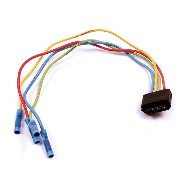
Sheath Material: No Panacea, Only Targeted Solutions
|
Characteristic Parameter |
Polyvinyl Chloride (PVC) |
Polyurethane (PUR/TPU) |
Chloroprene Rubber (Neoprene) |
Thermoplastic Elastomer (TPE) |
|---|---|---|---|---|
|
Operating Temperature Range |
-20°C ~ 70°C |
-40°C ~ 90°C |
-50°C ~ 105°C |
-50°C ~ 80°C |
|
Abrasion Resistance (Taber Abrasion) |
100-200 mg/1000r |
15-40 mg/1000r |
150-300 mg/1000r |
80-150 mg/1000r |
|
Oil Resistance (IRM902 oil, 70°C, 24h) |
Volume Swell >50% |
Volume Swell <10% |
Volume Swell 10-25% |
Volume Swell 20-40% |
|
UV/Weather Resistance |
Poor, requires stabilizers |
Good |
Excellent |
Good to Excellent |
|
Tensile Strength |
15-25 MPa |
35-50 MPa |
10-20 MPa |
10-25 MPa |
|
Approximate Cost Ratio |
1x |
2x - 3x |
3x - 4x |
1.5x - 2.5x |
PVC is the cost-priority choice, but its shortcomings are obvious. Its hardness is greatly affected by temperature; below -10°C it can become brittle and crack, above 60°C it begins to soften and deform.a drop of diesel on a PVC sheath can cause it to swell and become sticky within hours, reducing mechanical strength by over 70%.
Chloroprene rubber is born for extreme environments. It is inherently flame retardant (typically achieving V-0 rating), resistant to ozone, and has unparalleled weather resistance, with very slow performance degradation under UV exposure. A section of chloroprene rubber sheath exposed on the coast for 5 years can still retain over 80% of its elongation at break.
Sheath Thickness: Not Thicker is Better, But Precise Matching
Sheath thickness is clearly defined by national standards (e.g., GB/T) and international standards (e.g., UL, IEC); it is not set arbitrarily.
-
The thickness lower limit ensures basic mechanical strength. For example, according to UL 1581 standard, for equipment wire with an outer diameter below 3.5mm, the minimum average sheath thickness is 0.76mm, and the thinnest point at any measurement location must not be below 0.61mm. This thickness is calculated and tested as the baseline to prevent damage during normal installation and use.
-
Excessively thick sheath sacrifices flexibility, increases weight and cost. For a cable with a 10mm outer diameter, increasing the sheath thickness from 1.5mm to 2.5mm increases weight by about 30% and bending stiffness may be more than double, which is disastrous for applications requiring frequent movement.
Color and UV Resistance: Black is the Most Cost-Effective Solution
Sheath color is not just for identification; it's functional. Black, because it contains carbon black, is the natural most effective UV absorber. Under identical Arizona Exposure test conditions (ASTM G154), a black PUR sheath can retain over 85% of its tensile strength after 5000 hours of equivalent outdoor exposure; whereas a gray sheath of the same material might retain only 60%. Bright colors like orange and yellow are mainly used for safety identification (e.g., life-saving equipment), but their UV resistance requiresAdd more expensive light stabilizers to compensate.
3. Internal Waterproof Structure: Preventing "Longitudinal Water Ingress"
When the sheath is accidentally damaged, ordinary cables act like straws, allowing moisture to rapidly spread tens of meters along the conductor interstices, paralyzing the entire system. The solution is to build a longitudinal water barrier.
-
Gel Filling/Water-Blocking Compound: Fill the gaps between stranded conductors or between the shield and sheath with a special waterproof gel. This compound does not solidified, has thixotropy (viscous at rest, flows under pressure), and actively fills any gaps. When water intrudes from a damaged area, the gel confines it locally, preventing longitudinal spread. High-performance water-blocking compounds can limit water penetration to less than 3 meters within 96 hours under 0.3MPa water pressure.
-
Moisture Barrier / Dry Water-Blocking: This is a cleaner solution. Place yarns or tapes made of superabsorbent polymer (SAP) inside the cable. Upon contact with water, these materials rapidly swell into a gel-like state, increasing in volume by 100-300 times, forming a physical plug. This method avoids the installation inconvenience gels can cause, especially suitable for field-terminated connectors.
4. Shielding and Armoring: Countering Electromagnetic and Physical Attacks
-
Shielding Layer: In the marine environment filled with high-power radar, radios, and motors, electromagnetic interference (EMI) is ubiquitous. Using a braided copper shield with over 85% coverage can reduce external interference by 20-40dB, ensuring signal integrity. For very high-demand data transmission (e.g., Ethernet), an additional aluminum foil shield is added for 100% coverage.
-
Armoring Layer:Adding a layer of stainless steel wire braid or galvanized steel wire armor outside the sheath can withstand over 2000N of tensile force and continuous crushing and biting. Armoring significantly increases the cable's weight and stiffness, adding 50%-100% to the cost, but enables survival in extreme applications like trawling, mooring, and subsea robots.
Harness Routing and Installation Protection
In vessel electrical system failures, over 70% of problems are not caused by the equipment itself, but by mechanical damage and environmental erosion of the wiring harness. A single short circuit caused by harness abrasion can halt a main engine control unit worth hundreds of thousands, with indirect downtime losses potentially reaching thousands to tens of thousands of RMB per hour.
Harness routing planning and installation protection are far from simple "wiring"; they are precision engineering tasks that directly affect the vessel's full lifecycle reliability and operating costs. Their core objectives are threefold: prevent abrasion, prevent water pooling, and resist mechanical stress.
Path Planning
In vessel electrical system failures, chronic issues like insulation degradation and short circuits caused by internal water accumulation in harnesses account for over 35%. A harness without proper slope is like a blocked blood vessel; initially asymptomatic, it will quietly corrode conductors within one or two sailing cycles (approx. 1-3 years)
The repair cost is not just replacing a section of harness (material and labor ranging from 500-5000 RMB), but also the daily operational losses of tens of thousands of RMB caused by the shutdown of the core equipment it serves (e.g., radar, steering gear). The seemingly simple number of a 2% slope is the most easily overlooked yet cost-effective protective measure in engineering practice.
Slope is Designed, Not 'Made Do'
Use a laser level or total station to position within the cabin, ensuring the entire path from the starting point (e.g., bridge console) to the endpoint (e.g., stern equipment box) has a height difference satisfies total length × 2%. For example, a 40-meter long harness path requires a minimum height difference of 0.8 meters between the end point and the starting point. During actual construction, encountering obstacles like beams and pipes may necessitate increasing the slope appropriately to 3%-4%.
The Fatal Impact and Quantified Cost of "Water Pockets"
A "water pocket" is only 5 cm deep, under the vessel's continuous 5-15Hz vibration, will cause the water inside to atomization and intrusion the harness interior. This moisture can cause the insulation resistance of standard wires to plummet from over 500 MΩ to below 10 MΩ within 6 months, far exceeding the safe operating threshold for equipment (typically requiring >100 MΩ). For cables transmitting high-frequency digital signals (e.g., Ethernet, radar signals) like coaxial or twisted pair cables, water ingress directly alters their characteristic impedance (e.g., deviating by ±10% or more from the standard 50Ω or 75Ω), causing signal reflection, attenuation, and Bit Error Rate (BER) deterioration from 10⁻¹² to 10⁻⁶, manifesting as screen flicker and data packet loss.
Execution Tools and Acceptance Criteria: From "Approximate" to "Millimeter-Level"
-
Tool Upgrade: Abandon visual inspection;Must use a digital inclinometer. Its accuracy should reach 0.1 degrees (approx. 0.17% slope), costing only 200-500 RMB, a one-time investment avoiding potential losses of hundreds of thousands. Before fixing the harness, measure a point every 1.5 meters along the planned path to ensure continuous downward inclination.
-
Coordinate with Structure: The routing path should be as much as possible follow the vessel's inherent stiffeners or keel structure, which naturally have a 1-3% slope for drainage. Utilizing these structures allows extending the welding interval of harness supports (e.g., saddle clamps) from 30 cm to 50 cm, saving approx. 15% of installation materials and labor.
-
Data-Driven Acceptance: The final acceptance report should not just state "slope reasonable," but record the elevation data of key nodes.
Physical Protection
Statistics show that within the first five years of vessel operation, over 50% of mechanical failures in wiring harnesses – including insulation cuts, metal shield wear, and even wire breakage – occur at "critical nodes" along the path. These nodes account for less than 5% of the total harness length but represent 100% of the risk points.
Deck openings, bulkhead penetrations, and sharp edges on equipment brackets cause slight friction against the harness jacket dozens of times per minute during the vessel's continuous rolling (±10°) and pitching (±5°) over years. A set of nylon conduit and grommets costing only 200 RMB can extend the expected lifespan of the harness at critical nodes from 3 years to over 15 years, avoiding equipment repairs (averaging 5000-20,000 RMB) caused by short circuits.
Choosing the Right 'Armor': Protection Levels and Prices of Different Materials
|
Protection Type |
Applicable Temperature Range |
Abrasion Resistance (Reciprocating Cycles) |
UV/Salt Spray Resistance |
Cost Reference (RMB/meter) |
Most Suitable Scenarios |
|---|---|---|---|---|---|
|
PP (Polypropylene) Conduit |
-30°C ~ 100°C |
Medium (>5000 cycles) |
Fair, can become brittle |
5 - 15 |
Dry areas inside the cabin to prevent minor scratches |
|
PA66 (Nylon) Conduit |
-40°C ~ 125°C |
Excellent (>15000 cycles) |
Good, strong weather resistance |
15 - 30 |
Deck, engine room, most areas,首选 |
|
Stainless Steel Braided Sleeving |
-60°C ~ 500°C |
Outstanding (near infinite) |
Outstanding |
50 - 150 |
Near high-temperature exhaust pipes, heavily contaminated areas prone to oil immersion |
How to choose? Remember one principle: look at ambient temperature and friction frequency.
-
Engine Room Area: Average ambient temperature is 45-60°C, summer peaks may approach 80°C, use PA66 nylon conduit. PP conduit here would soften and deform in less than two years.
-
Near Exhaust Pipes: Radiant temperature may exceed 150°C, only stainless steel braided sleeving can withstand it, tolerating short-term temperatures up to 500°C.
-
Indoor Wheelhouse/Bridge: Stable temperature, no direct sunlight, PP conduit suffices, saving over 50% in cost.
Properly Donning the 'Armor': Incorrect Sizing Renders it Useless
-
Inner Diameter Must Have Allowance: The conduit's inner diameter should be 1.3 to 1.5 times the outer diameter of the harness at its thickest point. For example, if your harness bundle diameter is 20 mm, you should choose a conduit with an inner diameter of at least 26 mm (20 x 1.3). This 30% allowance is for:
-
Ease of Pulling: Reduces pulling resistance, saving labor time.
-
Heat Dissipation: The harness generates heat during operation and needs air convection space.
-
Vibration Accommodation: Prevents long-term tight contact between the conduit's inner wall and the harness jacket, creating new wear points.
-
-
Use Professional Tape for Joint Treatment: The connection points between conduit sections and transitions to equipment interfaces must be sealed by wrapping with high-temperature silicone self-amalgamating tape (not ordinary electrical tape!).
Grommets: The 'Lifesaver' Against Metal Sharp Edges
Even if an opening in sheet metal is hand-filed by a worker, under a microscope it's Still jagged. The vessel's long-term vibration at 5-15Hz causes the harness to scrape against these "Sawtooth" hundreds of times per minute.
-
Material Must Be Rubber: Grommets must be made of chloroprene or silicone rubber, with a hardness typically around Shore A 60-70. This hardness provides sufficient support力 while having some elasticity to absorb vibration.
-
Installation Requires 'Interference Fit': The grommet's outer diameter should be 1-2 mm larger than the opening diameter. Installation requires some force to "squeeze" it in, relying on the rubber's own elastic tension to tightly "hug" the opening edge, preventing shedding under vibration. A properly installed grommet cannot be easily pulled out of the opening by hand.
Regular Inspection: Protective Components Also Have a Lifespan
-
Inspection Cycle: Conduct a comprehensive inspection every 12 months (aligned with the vessel's annual survey).
-
Key Focus Areas:
-
Conduit Surface: Use a flashlight to check for fine cracks caused by long-term UV exposure.
-
Grommet Lip: Pinch it; check if the rubber has lost elasticity, hardened, or become brittle. Normal rubber lifespan is 5-8 years; consider replacement at expiry even if it looks intact.
-
Stainless Steel Braid: Check for broken wires. If the number of breaks exceeds 5% of the total strands, replacement is needed.
-
