What Are OEM Harness Standards
OEM harness standards mandate materials (22–24 AWG UL-listed copper), testing (≥50N pull force, -40°C to +125°C thermal cycling), and compliance with IPC/WHMA-A-620/ISO 9001 for consistency in original equipment integration.
OEM Harness Definition and Role
In the automotive sector, a single modern vehicle can incorporate over 1,500 individual wires stretching roughly 5 kilometers in total length. These harnesses can account for up to 50% of the total labor time during vehicle assembly and represent about 10–15% of the total cost of a vehicle’s electrical system. Their design is critical not only for performance but also for minimizing electrical failures, which are among the top three causes of vehicle recalls globally.
Unlike aftermarket solutions, OEM harnesses are designed for specific vehicle architectures, with tolerances as tight as ±0.2 mm on connector mating surfaces to prevent moisture ingress or vibration-induced failures. A well-designed harness can reduce assembly time by up to 30% compared to manual wiring, thanks to pre-fabricated layouts that slot into place during production. For example, in electric vehicles, high-voltage harnesses must handle continuous currents of 250 A or more and operate at voltages up to 800 V, with insulation capable of withstanding temperatures from -40°C to 150°C.
By using lighter gauge wires or materials like aluminum instead of copper, manufacturers can shave off 3–5 kg per vehicle, directly improving fuel efficiency or battery range. In terms of durability, OEM harnesses undergo validation testing simulating 10+ years of use, including exposure to high humidity (95% RH), salt sprays, and mechanical stress cycles exceeding 100,000 bends. These rigorous standards help ensure that electrical systems maintain 99.9% uptime over the vehicle’s lifespan, reducing warranty claims and boosting brand reliability.
From a functional perspective, harnesses integrate multiple electronic control units (ECUs)—modern luxury cars contain over 100 ECUs—that require seamless communication via protocols like CAN FD, with data rates up to 5 Mbps. The harness must minimize electromagnetic interference (EMI), often employing shielded cables that reduce noise by 20–40 dB. As vehicles become more software-defined, the harness also supports over-the-air (OTA) updates, requiring robust power delivery to compute modules drawing 30–100 W continuously.
Key Design Rules and Guidelines
It’s not just about connecting points A to B—it’s about ensuring signals travel cleanly, power is delivered reliably, and the entire assembly withstands years of vibration, temperature changes, and environmental exposure. For instance, a typical automotive harness must operate across a temperature range of -40°C to 125°C, resist exposure to fuels and chemicals, and endure vibration loads up to 30 Gs without failure. Up to 60% of harness-related recalls stem from connector issues, so precision in mating and sealing is non-negotiable.
For example, a wire carrying 10 A of continuous current in a 12 V system should typically use a 2.5 mm² cross-section to keep voltage drop under 0.5 V over a 5-meter run. Using an undersized wire can lead to overheating, with temperatures rising by 15–20°C above ambient, increasing resistance and accelerating insulation decay. In high-voltage applications (e.g., electric vehicles), designers must adhere to stricter standards: 600 V or 1000 V rated insulation, with clearances and creepages of at least 3.2 mm between terminals to prevent arcing.
OEMs often specify connectors with IP6K9K ratings for waterproofing and dust resistance, especially in underhood or underbody locations. These connectors use seals capable of withstanding high-pressure spray (100 bar) and immersion in 1-meter deep water for 30 minutes. Retention force is also quantified: primary latches must withstand 50–70 N of pull force, while secondary locks ensure engagement even if the primary mechanism fails. For example, a widely used automotive connector series like the GT 150 from TE Connectivity is tested over 500 mating cycles with a maximum insertion force of 35 N per circuit.
Harnesses must be secured with clamps every 150–200 mm to avoid overhangs that amplify vibration stress. In areas with high movement (e.g., near doors or engines), wiring must have 10–15% extra slack to avoid tension during operation. Abrasion resistance is improved by wrapping sections in corrugated conduit with a wall thickness of 0.5–0.8 mm or adding sleeving rated for 800°C for 30 minutes near exhaust components. Testing validates these choices: harnesses undergo 40–100 Hz vibration sweeps for 100+ hours and flex tests of 250,000 cycles at 0.5 Hz for dynamic applications.
In essence, a well-designed harness blends electrical precision with mechanical resilience, all while keeping manufacturing costs under $0.30–0.50 per wire terminations.
Standard Testing Methods Used
For example, a typical harness validation program includes over 50 distinct test types, ranging from electrical checks like continuity (resistance < 0.5 Ω per circuit) and hipot testing at 500–1000 V for 60 seconds, to mechanical stress tests such as vibration exposure at 10–2000 Hz for 100+ hours. These processes help reduce field failure rates to < 0.1% over the vehicle’s lifespan, directly impacting warranty costs and brand reputation.
| Test Category | Key Parameters | Duration/Cycles | Standard |
|---|---|---|---|
| Electrical Performance | Resistance (< 0.5 Ω), Voltage Drop (< 0.5 V @ 10 A) | N/A | ISO 6722 |
| Dielectric Strength | 500–1000 V AC, 60 sec | 60 seconds | ISO 16750-3 |
| Vibration Resistance | 10–2000 Hz, 30 G acceleration | 100 hours | USCAR-2 |
| Thermal Cycling | -40°C to 125°C, 5°C/min ramp | 500 cycles | ISO 16750-4 |
| Connector Mating Force | 35 N max per circuit | 500 cycles | LV 214 |
Continuity tests verify that every circuit has resistance below 0.5 Ω, while voltage drop measurements ensure losses remain under 0.5 V at 10 A load current over a 5-meter length. High-potential (hipot) tests apply 500–1000 volts AC for 60 seconds between conductors and shields to check for insulation breakdown—leakage current must stay below 1 mA throughout. For signal integrity, characteristic impedance is measured with a tolerance of ±5% for high-speed links like Ethernet, and crosstalk between adjacent wires is kept 40 dB below the signal level to prevent data errors.
Thermal cycling chambers subject harnesses to 500 cycles between -40°C and 125°C, with temperature ramps of 5°C per minute, to uncover cracking in insulation or connector seals. Humidity tests involve exposure to 95% relative humidity at 85°C for 500 hours, followed immediately by dielectric validation—insulation resistance must exceed 100 MΩ after this treatment. Salt spray testing runs for 96–200 hours using a 5% NaCl solution to evaluate corrosion resistance on terminals and contacts, with post-test resistance degradation limited to < 10 mΩ increase.
Vibration testing applies sinusoidal and random profiles from 10 Hz to 2000 Hz at amplitudes up to 30 G, monitoring for intermittent opens or shorts throughout the 100-hour test. Connectors undergo 500 insertion/extraction cycles with a maximum force of 35 N per circuit and must maintain < 5 mΩ contact resistance throughout. Retention force is verified by applying 50–70 N of pull force to mated connectors—separation is unacceptable. For abrasion resistance, wiring is rubbed against sharp edges or brackets for 1,000 cycles at 10 N force; insulation must not wear through to the conductor.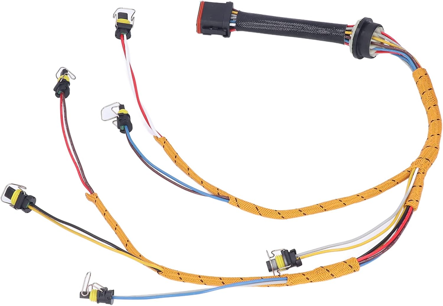
Common Industry Standards Overview
For instance, compliance with major standards can reduce vehicle development time by up to 20% and prevent costly recalls, which average over $500 per vehicle in the automotive sector. A single harness might need to satisfy 20+ different standards, covering everything from wire gauge tolerance (±0.02 mm) to flame propagation speed (< 100 mm/min). These regulations are not static; they evolve to address new technologies, such as 600-volt power systems in EVs and multi-gigabit data networks, making standardization a critical pillar for innovation and mass production.
| Standard Code | Primary Focus | Key Technical Requirements | Typical Application |
|---|---|---|---|
| ISO 6722 | Conductor & Insulation Performance | Temperature rating: -40°C to 125°C, Max voltage drop: 0.5 V/5m @ 20 A | Basic automotive wiring |
| USCAR-2 | Electrical Connector Performance | Vibration: 10-2000 Hz, 30 G, Mating cycles: 500 cycles @ 35 N max | All automotive connectors |
| LV 214 | Wiring Systems (German OEMs) | Current cycling: 1000 cycles, Crimp pull force: > 50 N for 0.35 mm² wire | BMW, VW, Mercedes |
| JASO D611 | Japanese Automotive Standards | Heat aging: 3000 hrs @ 85°C, Oil resistance: Δ volume < 10% | Toyota, Honda, Nissan |
| ISO 19642 | Road Vehicles - Cables | Abrasion: 1000 cycles @ 10 N, Flame retardancy: < 70 mm/min | Global vehicle platforms |
The ISO 19642 series, which is progressively replacing older standards like ISO 6722, provides a comprehensive classification system for automotive cables. It defines classes based on nominal voltage (e.g., 60 V vs. 600 V) and performance levels against thermal aging (e.g., 3000 hours at 125°C), fluid resistance (max 15% volume swell after immersion in engine oil), and abrasion resistance (minimum 100 cycles with a 10 N force using a standardized needle). A Class C cable, for example, must withstand a minimum of 40,000 flexing cycles at -40°C without cracking. This granularity allows designers to select the most cost-effective wire for each application, potentially saving $0.05–0.10 per meter in material costs across a vehicle’s 5 km of wiring.
For electrical connectors, USCAR-2 is the de facto standard in North America, defining everything from contact retention force (min 40 N for a 2.0 mm pin) to dielectric withstand (1000 V AC for 60 seconds). It mandates specific vibration profiles (10-2000 Hz at 30 G acceleration) and thermal shock cycles (-40°C to 120°C for 100 cycles) to validate performance. Meanwhile, the German LV 214 standard, used extensively by VW, BMW, and Mercedes, is often more stringent. It requires crimp pull forces exceeding 50 N for a 0.35 mm² wire and subjects connectors to current cycling tests (e.g., 1000 cycles from 10% to 100% of rated current) to simulate real-world load variations and uncover weaknesses in terminal design.
Supplier and Manufacturer Collaboration
In the automotive sector, where a single vehicle platform may contain over 5 km of wiring and 1,500+ connections, close partnership ensures that harness designs are optimized for performance, manufacturability, and total cost. For example, early supplier involvement (ESI) in the design phase can reduce development time by 20–30% and cut tooling costs by up to 15%, while collaborative value engineering often identifies material or process alternatives that save $10–25 per vehicle. With harnesses representing roughly 10% of a vehicle’s electrical system cost, this partnership directly impacts the bottom line.
| Collaboration Phase | Key Activities | Quantified Goals | Impact |
|---|---|---|---|
| Joint Design Review | DFM/DFA analysis, tolerance stacking | Reduce unique parts by 15%, cut assembly time by 20% | Lower complexity, fewer errors |
| Cost Targeting | Material substitution, process optimization | Achieve cost/sq meter < $40, reduce waste by 12% | Meet budget, improve margins |
| Prototyping & Validation | Rapid sampling, test failure analysis | Shorten sample cycles to 3 weeks, reach 0 PPM defects | Faster time-to-market |
| Production Ramp-Up | Line audits, capacity planning | Achieve 95% OEE, deliver 99.8% on-time | Stable supply, high quality |
The collaboration typically begins with joint design reviews using digital tools like 3D harness simulation software. Here, suppliers provide input on bundle diameters (optimized to within ±1.5 mm), bend radii (minimum 4x cable diameter), and connector placement (±0.3 mm accuracy) to avoid interference with adjacent components. They might recommend switching from a copper wire to a aluminum-based alloy for non-critical circuits, reducing weight by 30% and material cost by 20% per meter, without compromising performance for loads under 5 A. Suppliers also run Design for Manufacturing (DFM) analyses to ensure that harnesses can be assembled with automated machines achieving 98% efficiency, reducing manual labor which can cost $0.50–0.80 per termination.
“The most successful collaborations are built on shared data. OEMs provide 3D CAD models with ±1 mm accuracy, while suppliers feedback real-world manufacturability data, like the fact that automating a particular subassembly requires a minimum bend radius of 25 mm to avoid machine jams. This avoids late-stage design changes that can cost $50,000 or more per modification.”
Suppliers work with OEMs to break down harness costs by material (60–70% of total cost), labor (15–20%), and overhead (10–15%). Through value engineering, they might propose using cross-linked polyethylene (XLPE) insulation instead of PVC, which allows for a 10% reduction in wall thickness and a 5% lower material cost, while still meeting temperature ratings of 125°C. For terminals, switching from a proprietary design to a standardized USCAR-compliant connector can reduce unit cost by $0.15–0.25 and cut inventory carrying costs by 8%.
Future Trends in Harness Development
Where a traditional luxury vehicle contained roughly 5 km of wiring, new EV platforms like Tesla’s Cybertruck or GM’s Ultium are pushing 10-12 km per vehicle to support 800-volt battery systems and redundant sensor networks. This evolution isn’t just about more copper; it’s about smarter, lighter, and more integrated systems that reduce weight by up to 15%, cut assembly costs by 20%, and enable data transfer rates exceeding 10 Gbps. The next generation of harnesses will be defined by four key shifts:
- 48-Volt Architecture Adoption
- High-Speed Data Networks Integration
- Lightweight Material Innovation
- Additive Manufacturing and Automation
The transition to 48-volt electrical systems is accelerating to power energy-intensive features like steer-by-wire, active suspension, and high-performance computing modules. A 48V architecture allows for 75% less current compared to a 12V system to deliver the same power, enabling the use of thinner-gauge wires (e.g., 4 mm² instead of 25 mm²) for the same load. This translates to a 3-4 kg weight reduction per vehicle and 15-20% lower wiring cost for power-intensive circuits. These systems operate with 98% efficiency and are critical for supporting loads like 3-5 kW active anti-roll bars or 1.2 kW regenerative braking systems without the penalty of excessive weight and cost.
As vehicles process 5-20 terabytes of data daily from cameras, lidar, and radar, harnesses must carry multi-gigabit signals without loss. Ethernet IP (IEEE 1000BASE-T1) is becoming the backbone, requiring shielded twisted-pair cables with impedance tightly controlled to 100 Ω ±10%. To maintain signal integrity at 10 Gbps data rates, skew must be managed to < 50 ps/meter, and insertion loss kept below -3 dB at 500 MHz. This demands new connector designs with > 40 dB crosstalk rejection and impedance matching within ±5%. These harnesses are no longer just power carriers; they are data highways where a 0.5 mm misalignment in a connector can corrupt an entire sensor stream.
A robust OEM harness ensures compliance with industry specs (e.g., 22AWG wire gauge for 15A circuits) via strict design rules (3mm min. connector spacing) and ISO 26262/SAE J2534 testing (IP67 waterproof checks per IEC 60529). Supplier collaboration uses PPAP documentation, aligning with 0.1mm tolerance standards for future lightweight aluminum conductor trends.
