What Are the Main Types of Wire Harness Connectors
Main wire harness connectors include circular (M12/M8, IP67-rated for dust/water), rectangular (AMPSEAL 16 with 16 pins for power/data), high-frequency (SMA, 18GHz bandwidth), and waterproof (IP68, tested via 24hr 1m depth submersion).
Circular Connectors Overview
Characterized by their cylindrical shape and a screw-on coupling mechanism that ensures a secure, vibration-proof seal, these connectors are the default choice where reliability is non-negotiable. The global market for them is substantial, valued at over $13.5 billion, reflecting their critical role across countless applications. Their design is so effective that a single connector can integrate 3 to 100+ individual contacts, handling currents from a few milliamps for data signals up to 250 amps or more for high-power applications, all within a shell that might be as small as 10 mm in diameter for miniature versions or over 50 mm for heavy-duty industrial use.
A common rating for industrial equipment is IP67, which guarantees complete protection against dust and the ability to withstand immersion in 1 meter of water for 30 minutes. For more demanding environments, like on a factory washdown floor, you might see IP69K, which signifies resistance to high-pressure, high-temperature water jets. The mechanical backbone of this seal is the threaded coupling system. It takes roughly a quarter to a half turn to fully engage and lock most connectors, creating a seal that can resist pull-out forces exceeding 50 Newtons (N) and withstand 1,000+ mating cycles before any significant wear occurs.
These contacts are typically made from copper alloys and plated with 1 to 3 microns of gold or silver to ensure low electrical resistance and prevent corrosion. The size of the contact, often coded by a number like 16, 20, or 24, directly dictates its current-carrying capacity. A size 16 contact can typically handle 13 amps, while a size 24 might be rated for just 5 amps.
The fundamental advantage of a circular connector is its mechanical simplicity and resilience. The screw-on coupling provides a reliably secure connection that is virtually impossible to accidentally disconnect, making it ideal for high-vibration environments like those found in automotive engines, aerospace systems, and heavy industrial machinery where a loose connection could lead to critical system failure.
For the most extreme conditions, such as in aerospace or deep-sea equipment, shells are machined from stainless steel or aluminum with advanced plating. These connectors are engineered to perform in temperature extremes, from -55°C to +125°C or even higher, ensuring functionality whether installed on a drill rig in the desert or a sensor array in the arctic.
Rectangular Connector Types
Rectangular connectors are the workhorses of internal device wiring and panel connections, prized for their efficient use of space and high contact density. Unlike their circular counterparts, their shape is ideal for aligning with printed circuit board (PCB) edges and fitting into flat or angled surfaces within equipment. They are fundamental in industries from consumer electronics to industrial automation, with the global market consuming billions of units annually. A standard 0.100-inch (2.54 mm) pin pitch connector can host over 100 positions in a housing just a few inches long, allowing for the consolidation of dozens of signal and power lines into a single, compact interface. Their cost-effectiveness is a major driver, with simple pin-header versions costing less than $0.05 per contact in high-volume purchases.
|
Feature |
Common Specifications |
Typical Applications |
|---|---|---|
|
Pin Pitch |
0.100" (2.54mm), 0.050" (1.27mm), 2.00mm, 5.08mm |
PCB-to-PCB, PCB-to-Cable |
|
Current Rating |
1A to 50A+ per contact |
Signal, Power Distribution |
|
Voltage Rating |
30V AC to 1000V+ AC |
Low-voltage Logic, AC Power |
|
Locking Mechanism |
Friction Latches, Screw Locks, Lever Actuators |
Consumer Goods, Industrial Machinery |
|
IP Rating |
IP00 (unrated) to IP67 (dust-tight, waterproof) |
Internal Wiring, Harsh Environments |
The defining characteristic of these connectors is their pin pitch—the center-to-center distance between contacts. This dimension is critical for PCB layout and determines the connector's density. While the historic 0.100-inch pitch remains ubiquitous, the push for miniaturization has made 0.050-inch and 2.00-millimeter pitches standard in compact devices. For high-power applications within the same form factor, pitches widen to 5.08 mm or 7.62 mm to accommodate heavier wiring and prevent arcing. The contacts themselves are typically made from phosphor bronze or brass and are plated with either 3-5 microinches of gold for low-energy signal applications or 50-100 microinches of tin for higher-current, cost-sensitive power applications. The choice of plating directly impacts durability and resistance; gold plating maintains stable contact resistance for over 10,000 mating cycles, while tin plating is more susceptible to fretting corrosion but is significantly less expensive.
Simple friction-fit connectors, common in consumer electronics, have a relatively low retention force, often under 15 Newtons (N) of pull-out pressure. For anything subject to vibration or movement, a positive lock is required. Screw locks provide the most robust solution, capable of withstanding vibrations exceeding 15 Gs and pull-out forces over 50 N. Lever-actuated connectors, common in factory automation (e.g., JST VG series), offer a tool-less, quick-disconnect feature that can mate and unmate in under 2 seconds while still maintaining a secure connection rated for 500 to 5,000 cycles.
Environmental sealing is another key factor. Unrated (IP00) connectors are fine for protected device internals, but connectors used in agricultural or automotive applications require an IP67 rating, meaning they must be dust-tight and survive immersion in 1 meter of water for 30 minutes. This is achieved through silicone grommets and seals that compress with a specific force, typically between 5 and 10 N per linear centimeter of seal length, when the connector is fully mated. The housing material also plays a role; nylon 66 is common for its cost and strength, but for high-temperature environments near 125°C or exposure to fuels and oils, more expensive plastics like PPS or PBT are used.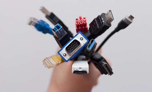
PCB Mounted Connectors
PCB-mounted connectors are the fundamental interface between a printed circuit board and the rest of a system, serving as the permanent termination point for all external signals and power. Unlike wire-to-wire connectors, they are soldered directly to the board, creating a fixed and reliable link. Their selection critically impacts manufacturing efficiency, reliability, and final product size. The global market for these connectors is vast, driven by the production of billions of PCBs annually for everything from smartphones to industrial controllers. Miniaturization is a key trend, with pitch sizes shrinking from the traditional 2.54 mm to a common 0.5 mm and even down to 0.35 mm for high-density applications, allowing for over 400 pins on a connector shorter than 50 mm in length. The choice of connector directly influences assembly time and cost, with simple headers taking less than 5 seconds to place and solder via automated pick-and-place machines.
|
Feature |
Common Specifications |
Impact on Design |
|---|---|---|
|
Mounting Style |
Through-Hole (THT), Surface Mount (SMT), Press-Fit |
Manual vs. Automated Assembly, Board Strength |
|
Typical Pitch |
2.54mm, 2.00mm, 1.27mm, 1.00mm, 0.80mm, 0.50mm |
Board Real Estate, Density |
|
Current Rating |
1.0A to 5.0A+ per pin (signal), 10A+ (power) |
Power Distribution, Trace Width |
|
Voltage Rating |
50V AC to 500V+ AC |
Isolation, Creepage Distance |
|
Mating Cycles |
25 to 10,000+ |
Field Service Life, Reliability |
The primary division in this category is between through-hole (THT) and surface-mount (SMT) technology. THT connectors, with pins inserted into drilled holes and soldered, provide a mechanically superior bond, withstanding over 20 Newtons (N) of pull-out force, making them ideal for connectors that undergo frequent mating cycles or mechanical stress. However, they require more board space and are slower to assemble. In contrast, SMT connectors are soldered directly to the surface of the PCB, enabling fully automated assembly at speeds exceeding 25,000 components per hour. They dominate high-volume production for consumer electronics. A critical parameter for SMT connectors is coplanarity—the tolerance that all leads sit in the same plane—which is typically specified to be less than 0.10 mm to ensure a reliable solder joint during reflow soldering cycles that peak at 240-260°C for 30-60 seconds.
Standard connectors use nylon (PA) or polyester (PBT) plastics with a relative thermal index (RTI) of 105°C to 125°C, sufficient for most applications. For lead-free reflow soldering processes with peak temperatures reaching 260°C, high-temperature plastics like LCP (Liquid Crystal Polymer) or PPS are mandatory to prevent deformation. The contact pins are typically made from phosphor bronze or brass and are the critical factor for current rating. A 0.64 mm square pin in a standard header is often rated for 3.0 amps, but this can drop to 1.0 amp for finer pitches below 1.00 mm due to reduced cross-sectional area. The plating finish on these pins is a major cost and performance driver. A 0.76 µm (30 µ-inch) gold flash over nickel is a common, cost-effective solution for up to 1,000 mating cycles, while a 1.27 µm (50 µ-inch) hard gold plating is specified for applications requiring 10,000 cycles or harsh environments to maintain a stable contact resistance of under 20 milliohms. For power connectors, the parameters shift dramatically. A 5.08 mm pitch terminal block mounted on a PCB can facilitate the connection of 16 AWG wire and carry 15-20 amps continuously, necessitating a 4-6 oz copper weight on the PCB for the underlying traces to handle the current without excessive heating.
RF Coaxial Connector Uses
Their primary function is to maintain the integrity of a signal traveling at frequencies from 500 MHz to 110 GHz, a critical requirement in modern wireless systems. The global RF connector market, valued at over $5 billion, is driven by the expansion of 5G infrastructure, which requires millions of base stations each utilizing hundreds of connectors. Unlike standard connectors, their performance is measured by impedance, typically 50 ohms (standard for telecom and datacom) or 75 ohms (standard for video broadcast), and their ability to minimize signal reflection, quantified by a Voltage Standing Wave Ratio (VSWR) as low as 1.05:1 at 6 GHz for high-precision types. Even a minor impedance mismatch can result in a 20% power loss, making connector selection paramount.
-
BNC (Bayonet Neill-Concelman): A quick-connect bayonet coupling used extensively in test equipment and video broadcasting for frequencies up to 4 GHz, with a typical VSWR of 1.3:1.
-
SMA (SubMiniature version A): A screw-type connector ubiquitous in cellular radios, Wi-Fi modules, and GPS units, rated for frequencies up to 18 GHz (commercial grade) and 27 GHz (precision grade), handling power levels up to 500 watts at 1 GHz.
-
N-Type: A larger, threaded connector designed for base station infrastructure and high-power applications, capable of handling frequencies up to 11 GHz and power levels exceeding 1000 watts at 100 MHz.
-
QMA: A quick-lock version of the SMA, used in industrial settings where rapid installation is needed, performing reliably up to 18 GHz with a mating cycle life of over 500 connections.
For instance, an N-Type connector's larger size limits its optimal performance to below 11 GHz, while an 2.92 mm connector can operate up to 40 GHz. The primary metric for signal efficiency is Insertion Loss, which quantifies the signal power lost within the connector itself. A high-quality SMA connector adds less than 0.05 dB of loss per connector at 10 GHz, but this value can degrade to over 0.2 dB with a poorly manufactured or worn unit. This loss translates directly into heat; a connector handling 100 watts of power with a 0.1 dB loss will dissipate approximately 2.3 watts of thermal energy, requiring consideration for thermal management in high-power arrays.
The center contact is typically made from beryllium copper and plated with 1.27 to 2.54 µm (50 to 100 µ-inches) of gold over nickel to ensure low surface resistivity (under 5 milliohms) and corrosion resistance. The dielectric material separating the center pin from the outer shell is usually PTFE (Teflon), chosen for its stable dielectric constant (εr ≈ 2.1) and low loss tangent (0.0004) across a wide temperature range from -55°C to +165°C. The durability, or mating cycle life, is a key cost factor. Commercial-grade SMA connectors are rated for 500 cycles, while precision versions designed for lab equipment use hardened materials and thicker platings to maintain a VSWR below 1.15:1 for over 5,000 cycles.For applications involving constant connection and disconnection, the physical torque applied during mating is specified to ensure longevity; hand-tightening an SMA connector to 5-10 inch-pounds of torque is sufficient, while under- or over-tightening can alter the impedance and drastically increase VSWR, leading to a 15% or greater decrease in signal transmission efficiency.
Automotive Connector Styles
Unlike commercial-grade components, they must guarantee near-perfect reliability over a vehicle's 15-year service life and 150,000-mile lifespan. A single modern vehicle contains over 1,500 individual connectors, totaling more than 3,000 terminal pins, creating a network that is absolutely critical to functionality. The failure of one 40,000 vehicle, making performance non-negotiable. These components are designed to stringent global standards like USCAR, requiring them to withstand 100 G of vibrational acceleration and operate reliably in temperature ranges from -40°C to +125°C (and up to +150°C in under-hood applications), all while maintaining a contact resistance of under 20 milliohms.
-
Sealed Metri-Pack (USCAR): The global standard for under-hood and body electronics, featuring a CPA (Connector Position Assurance) clip and secondary TPA (Terminal Position Assurance) lock. Rated for currents from 4A to 30A, with IP6K9K sealing against high-pressure, high-temperature washdowns.
-
GT 150/280: A common European-style connector for body control modules, sensors, and lighting. The number denotes the cavity size (150 = 1.5 mm², 280 = 2.8 mm²), supporting wire gauges from 20 AWG to 16 AWG and currents from 8A to 20A.
-
HSD (High-Speed Data): Shielded connectors for infotainment (MOST, Ethernet) and camera systems, handling data rates from 100 Mbps to 6 Gbps while suppressing EMI/RFI to meet CISPR 25 standards.
-
Battery Management System (BMS): High-voltage connectors for EV/HEV applications, handling 60V to 800V+ and currents exceeding 200A, with HVIL (High-Voltage Interlock Loop) safety circuits.
The primary lock is the terminal tang, a spring-metal feature on the female terminal that snaps into a cavity inside the connector housing, providing a retention force between 30 and 70 Newtons (N). The TPA (Terminal Position Assurance) device is a separate orange or red plastic slider or clip inserted after the terminals are loaded. It locks the terminal tangs in place, preventing them from deflecting and loosening under vibration, and increases the retention force by an additional 15-25%. Finally, the CPA (Connector Position Assurance) clip locks the male and female connector housings together, ensuring an audible "click" is heard during mating and preventing unintended decoupling from impacts. This system ensures the connector can withstand vibrational frequencies from 10 Hz to 2,000 Hz without signal interruption.
Sealing performance is quantified by its IP (Ingress Protection) rating. A rating of IP67 is common for under-body connectors, meaning they are dust-tight and can survive immersion in 1 meter of water for 30 minutes. This is achieved through a combination of precision-molded housings and silicone rubber seals. The primary seal is located at the interface between the two connector halves, compressed to approximately 70-80% of its original diameter when mated. Secondary wire seals are crimped onto the wire behind the terminal, preventing moisture from wicking along the wire strands. The housing material is almost always a high-temperature, chemically resistant thermoplastic like PBT (Polybutylene Terephthalate) or Nylon 66 (PA66), often with a 30-35% glass filler to increase tensile strength and reduce thermal expansion. The terminals are phosphor bronze or brass, plated with 0.8 µm of tin for cost-sensitive applications or a 1.27 µm Sn/Cu (tin-copper) alloy for better fretting corrosion resistance. This plating must maintain stable electrical performance for over 500 mating cycles and throughout 15 years of exposure to temperature cycling and humidity, with a failure rate of less than 20 ppm (parts per million) over the vehicle's lifespan.
Terminal Block Applications
A single large industrial control panel might contain over 500 terminal points, connecting everything from 24V DC sensor signals drawing less than 100 mA to 480V AC motor power lines carrying over 50 amps. The global market for terminal blocks exceeds $3.5 billion, driven by their indispensability in automation and infrastructure. Their design allows for tool-less maintenance in under 30 seconds per wire, drastically reducing downtime and labor costs compared to hardwired solutions.
|
Type |
Key Specifications & Data |
Primary Application Environment |
|---|---|---|
|
PCB Mount |
Pitch: 3.5mm, 5.0mm, 7.5mm, 10.0mm; Current: 2A to 25A; Voltage: 150V to 300V; Wire Gauge: 30-12 AWG |
Internal board-level power and signal distribution within devices. |
|
DIN Rail Mount |
Current: 15A to 300A+; Voltage: 300V to 1000V; Wire Gauge: 24-4/0 AWG; Clamping Force: >50 N |
Industrial control panels, motor control centers, power distribution. |
|
Barrier Strip |
Current: 15A to 60A; Voltage: 300V to 600V; Wire Gauge: 24-10 AWG; Material: Phenolic or Polyamide |
HVAC units, marine equipment, transportation, high-vibration environments. |
|
Feed-Through |
Current: 20A to 250A; Voltage: 300V to 600V; Wire Gauge: 24-4/0 AWG; IP Rating: IP20 to IP67 |
Connecting wires from two separate compartments through a panel wall. |
A block rated for 20 amps will typically have a copper alloy bar with a 3.0 mm² cross-section, while a 100-amp block requires a bar of at least 25 mm². The clamping mechanism is equally critical. Screw-type clamps remain the most common, applying 20 to 70 Newtons (N) of force to the conductor, creating a stable connection with a contact resistance of < 0.5 milliohms. For applications subject to vibration, spring-cage clamps (e.g., CAGE CLAMP®) are superior. They use a stainless steel spring to maintain a constant force of 30-50 N on the wire, compensating for thermal expansion and vibration, and are rated for over 1,000 operating cycles with minimal resistance drift. The insulation housing, typically made from polyamide (PA66) with a UL94 V-0 flammability rating, must have a Comparative Tracking Index (CTI) of >250 volts to prevent carbon tracking and short circuits in humid environments.
The current bar/plate is often made from electrolytic copper (Cu-ETP) with a tin (Sn) or nickel (Ni) plating at least 5 µm thick to prevent oxidation and ensure a stable, low-resistance interface. The housing must possess a high Glow-Wire Ignition Temperature (GWIT), typically >775°C, to withstand electrical faults without igniting. For DIN rail mounting, the standard rail is 35 mm wide, and a single meter of rail can hold up to 60 individual terminal blocks, organizing thousands of connections in a single enclosure. The creepage and clearance distances are legally mandated by international standards (IEC 60664-1). For a 300V AC rating, a minimum creepage distance of 4.0 mm is required to prevent surface arcing, while a clearance distance of 3.0 mm prevents airborne arcs. For 600V AC, these distances increase to >8.0 mm and >5.5 mm, respectively.
The fundamental advantage of a terminal block is its role as a central, high-integrity junction point. It transforms a chaotic web of individual wire splices into a standardized, labeled, and serviceable interface. This modularity allows for easy circuit testing, modification, and troubleshooting, reducing mean time to repair (MTTR) by up to 70% compared to hardwired systems.
Standard blocks have an IP20 rating, protecting only against finger contact. For harsh environments, blocks with an IP67 rating are essential. They achieve this through integrated silicone seals around each wire entry and between the housing and the DIN rail, capable of repelling dust and withstanding immersion in 1 meter of water for 30 minutes. The operating temperature range for most industrial-grade blocks is -40°C to +120°C, with the high-temperature limit constrained by the plastic's relative thermal index (RTI) and the spring force of the clamp. The total cost of ownership is low; while a single 15-amp block may cost 1.00, it eliminates the need for labor-intensive soldering or crimping, reduces wiring errors by over 30%, and provides a failsafe point for maintenance for the entire 20-year lifespan of a control system.
A primer on wire harness connectors covers six core types: circular connectors (IP68-rated, 10GΩ insulation resistance for harsh environments), rectangular connectors (30-pin standard for industrial controls, 2.54mm pitch), PCB-mounted types (0.5mm spacing for SMT assembly), RF coaxial variants (SMA connectors with ≤1.5 VSWR for 0-6GHz signals), automotive styles (AEC-Q200 certified, -40°C to 125°C), and terminal blocks (10-20A current capacity, screw/spring clamping). Each type optimizes connectivity for specific operational demands.
