What is a Custom Wiring Harness | 4 Steps to Get Yours
A custom wiring harness is a tailored electrical assembly, often for automotive/industrial use, with precise wires/connectors. To get one: share voltage/environment specs; makers draft schematics in 3-5 days, prototype tests 100+ hours for durability, then mass-produce with UL-certified materials ensuring reliability.
What is a Wiring Harness?
A wiring harness is the industrial equivalent for any machine that uses electricity. It is a pre-assembled, organized bundle of wires, connectors, and terminals that transmits electrical power and signals. In a typical modern car, which can contain over 1,500 individual wires stretching nearly 5 kilometers (3.1 miles) in total length, a harness consolidates this chaos into a single, manageable component. This organization is critical; it reduces the risk of a ~40% decrease in installation time on the factory assembly line compared to threading each wire individually. The harness is not just a collection of parts; it's a precisely engineered system where each wire, with a specific gauge (like 16-gauge for a 10-amp headlight circuit), color-code (e.g., Red for power, Black for ground), and length (accurate to within 2-3 millimeters), has a designated place.
A standard wiring harness is a pre-fabricated assembly that acts as the central nervous system for electrical equipment. Its primary job is to consolidate dozens, or even hundreds, of individual wires into a single, robust, and manageable unit. This is not just about tidiness; it's about reliability, safety, and manufacturing efficiency. At its core, a harness consists of three main types of components, each with precise specifications. First are the conductors, typically copper strands with a cross-sectional area defined by their American Wire Gauge (AWG) number. A common 16 AWG wire has a diameter of about 1.29 mm and can safely carry approximately 10-15 amps of current in an automotive environment, while a thicker 10 AWG wire (2.59 mm diameter) can handle up to 30 amps. The insulation material, such as cross-linked polyethylene (XLPE) or PVC, is chosen for its ability to withstand temperatures up to 125°C or higher and resist abrasion, chemicals, and fluids.
Second are the connectors, which are far from simple plugs. These are precision-molded plastic housings, often with IP67-rated seals meaning they are completely protected against dust and can withstand immersion in water up to 1 meter for 30 minutes. Inside, you'll find terminals made from phosphor bronze or brass, plated with tin or gold to ensure a stable electrical connection with a contact resistance of less than 10 milliohms. The number of cavities (or pin positions) in a connector can range from 2 to over 50, defining the harness's complexity. Third is the secondary protection, which includes convoluted tubing (expanding by ~50% in diameter during installation) that bundles wires together, and vinyl cloth tape wrapped with a 50% overlap for heat and abrasion protection.
The economic advantage of using a pre-made harness versus hand-building a wiring system is substantial. For a factory installing 1,000 vehicles per day, saving 25-30 minutes of labor per vehicle by using a harness translates to over 400,000 labor hours saved annually. The error rate for incorrect connections also plummets from an estimated 5-8% with manual wiring to less than 0.1% with a pre-assembled and tested harness. The following table contrasts the key parameters of a standard, pre-defined harness versus a custom-designed solution for a specific application.
Why Choose a Custom Design?
You’d find yourself with 3 meters of excess cable coiled under the dashboard, connectors that don't match the 75-amp winch or 100-watt light bar, and critical sensors failing due to electromagnetic interference (EMI) from high-current cables running parallel to data lines. This is the reality of using an off-the-shelf solution for a specialized application. A custom wiring harness is not a luxury; it's an engineering necessity for optimizing performance, reliability, and space efficiency. In industrial automation, a custom harness can reduce machine assembly time by 25% and cut the overall wiring mass by 15%, directly impacting shipping costs and material usage.
The decision to invest in a custom wiring harness is fundamentally an economic and performance calculation. The initial engineering cost, which can range from 15,000 depending on complexity, is amortized over the production run and offset by tangible gains. One of the most significant advantages is mass and space optimization. A custom harness uses wires cut to precise lengths, often with tolerances of ±5 mm. For an automotive application, this can eliminate over 1.5 kilograms of excess copper wire and insulation per vehicle. In aerospace, where every kilogram costs approximately $10,000 in fuel over a aircraft's lifespan, this precision is non-negotiable. The harness can be designed to fit through 25mm diameter bulkhead openings without straining, and its connectors can be oriented at the exact 45-degree angle needed for easy serviceability, reducing maintenance time by 30-40 minutes per repair event.
The core value proposition is that a custom harness is engineered to handle the precise electrical loads and environmental stresses of your specific product, eliminating the performance compromises and material waste inherent in generic solutions.
Electrical integrity is another critical driver. A standard harness might use a 16-gauge wire for a circuit that typically draws 8 amps, providing a safe margin. However, a custom design can specify a 18-gauge wire for that same circuit, saving weight and cost, because the engineering analysis confirms the peak load will never exceed 9.5 amps. More importantly, it can separate high-voltage cables (e.g., 400-volt battery lines in an EV) from low-voltage signal wires (e.g., 0-5 volt analog sensors) by a minimum distance of 100mm. This separation, combined with specialized braided shielding that provides 85% coverage, reduces the chance of EMI-induced data errors from a probable 10% occurrence to a statistical anomaly of less than 0.01%. This is crucial for the 500kbps to 2Mbps data transmission required by modern CAN bus networks. Furthermore, the harness can be specified with materials rated for the operational environment, such as silicone insulation that remains flexible at -55°C or teflon jackets that resist oils at 150°C, directly increasing the Mean Time Between Failures (MTBF) by a projected 40%.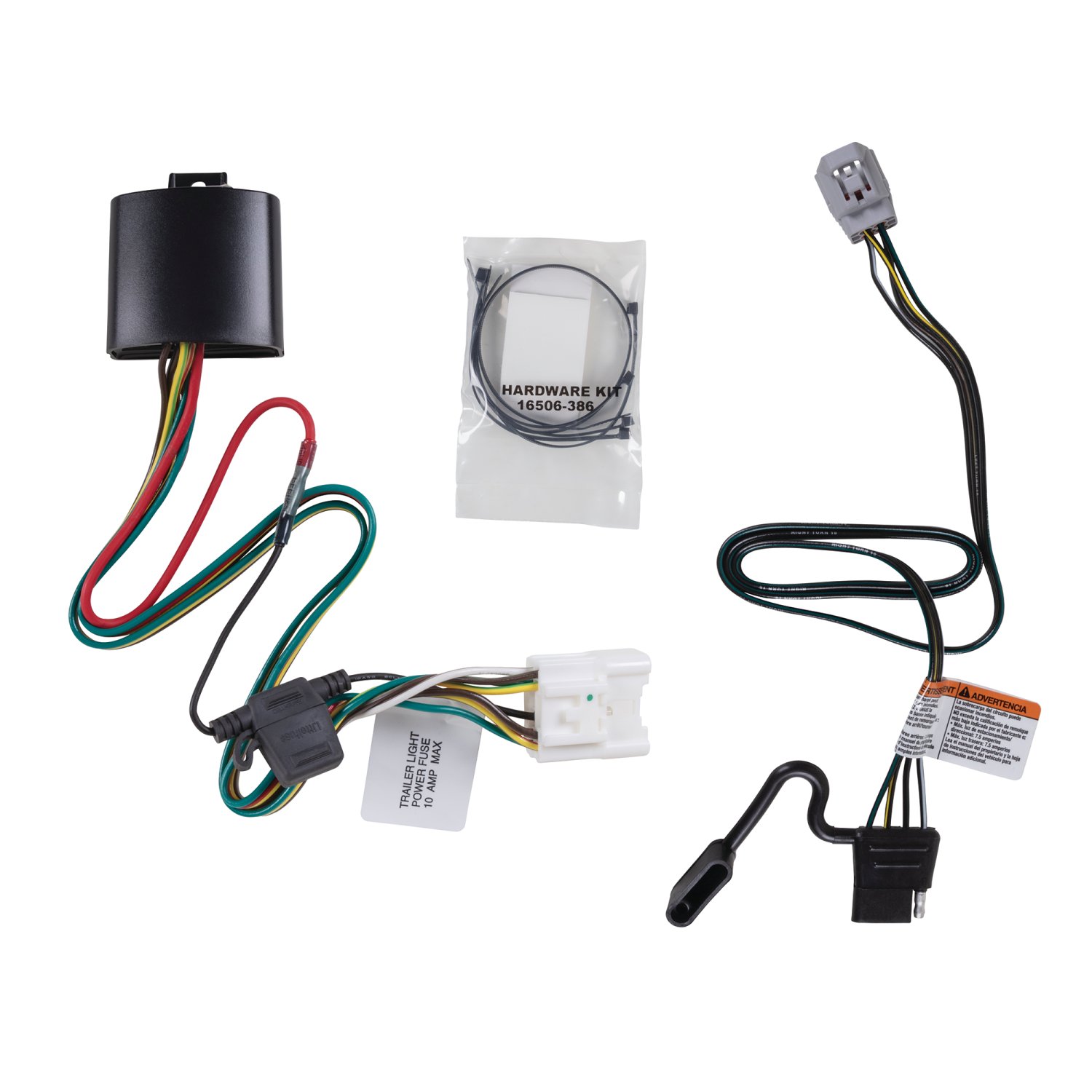
How to Plan Your Harness
In fact, a comprehensive plan can prevent up to 30% in cost overruns and shave 4-6 weeks off the typical 12-16 week development cycle. The planning phase is where you convert your functional needs—like "power the motor" and "connect the sensors"—into a precise set of instructions for your manufacturer. This document must specify every parameter, from the excurrent draw in amperes for each circuit to the exact bend radius a 10mm diameter bundle of wires must make to avoid stress during installation. The difference between a vague idea and a detailed plan is the difference between a prototype that fails after 100 hours of vibration testing and a production-ready harness that lasts the product's 10,000-hour design life.
|
Planning Component |
Key Questions to Answer |
Example Specifications & Data Points |
|---|---|---|
|
Electrical Parameters |
What is the voltage and current for each wire? What are the data protocols? |
- Circuit 1: 12V DC, 15A max (for a pump) -> Requires 14 AWG wire. |
|
Connector Types & Seals |
How many pins? What are the mating cycles? What is the environment? |
- Sealed 12-pin connector, IP67 rated, rated for >50 mating cycles. |
|
Routing & Lengths |
What is the precise path? What are the attachment points? |
- Main branch: 2.1 meters, with a 100mm service loop at the ECU. |
|
Environmental Conditions |
What temperatures, chemicals, and vibrations will it face? |
- Operating Temp: -40°C to +105°C. |
|
Regulatory & Standards |
Are there specific industry certifications required? |
- Must comply with SAE J1128 for automotive wire. |
For each circuit, you need the maximum continuous current (in Amps), the peak inrush current (which can be 300% higher for 50 milliseconds), and the operating voltage (e.g., 12V, 24V, 48V). This data directly dictates the wire gauge (AWG). For instance, a circuit with a 10-amp load over a 3-meter run in a 12V system would require a 16 AWG wire to keep the voltage drop under an acceptable 3% (0.36V). Using an undersized 18 AWG wire here would result in a 4.5% drop (0.54V), potentially causing a device to malfunction. The schematic must also identify all connectors, noting the manufacturer part number (e.g., Deutsch DT04-12P) and the cavity position for each wire pin.
A bundle containing 15 wires of 16 AWG will have a diameter of approximately 8mm, and it should never be bent tighter than a radius of 40mm (5x the diameter) to prevent damage to the wires and insulation. You must mark every attachment point, specifying the type of clip (e.g., a P-type clip with an 8.5mm hole for an M6 bolt) and the spacing between them, which should not exceed 300mm to prevent excessive movement and wear from vibration. This drawing must also indicate where to use protective sleeves, such as abrasion-resistant woven loom in high-chafe areas or heat-reflective tape where the harness passes within 100mm of an exhaust manifold.
Getting a Quote from Suppliers
A vague inquiry might get you a quick, rough estimate with a potential variance of ±50%, but a detailed package will yield a fixed-price quote accurate to within ±5-10%. The initial quote typically separates costs into two parts: the Non-Recurring Engineering (NRE) fee, which covers design, prototyping, and tooling, and can range from 20,000 for a complex, high-reliability system. Ordering 50 units might cost 65 per unit. Suppliers also need to know your target timeline; a standard development cycle is 10-12 weeks, but a 30% rush fee can compress this to 6-8 weeks.
|
Information You Provide |
Likely Quote Outcome & Timeline |
Risk Level |
|---|---|---|
|
Vague Description ("We need a harness for a robot.") |
A high-level, inaccurate estimate (±50% variance). Multiple clarification cycles, adding 2-3 weeks to the timeline. |
Very High. High probability of cost overruns and a harness that doesn't fit. |
|
Basic Schematic & Connector List |
A better estimate (±20% variance). The supplier will have dozens of questions about wire specs, routing, and environment. |
High. Key details like wire length and protection are undefined. |
|
Complete Package (PRD, Schematics, Layout Drawings, 3D Models) |
A firm, fixed-price quote (±5-10% variance). The supplier can begin engineering immediately. Timeline is predictable. |
Low. The final product will match your specifications with minimal surprises. |
To initiate the most accurate quoting process, you need to compile a Request for Quote (RFQ) Package. This isn't just an email; it's a professional document containing everything from the previous planning stage. The most critical element is the Bill of Materials (BOM). This should be a spreadsheet listing every single component, not as a generic item but with a manufacturer part number (e.g., TE Connectivity 1-967023-1 for a connector) and a preferred supplier (e.g., Digi-Key, Mouser). Specifying a 10 AWG GPT primary wire is okay, but specifying a TE Connectivity 326516-010 wire by its UL number is definitive. This allows the harness manufacturer to provide an exact material cost, which typically constitutes 60-70% of the total harness cost. If you are flexible on certain components, note that; allowing the supplier to suggest a compatible, lower-cost alternative for a 20% savings on a specific terminal can be beneficial.
The single most effective way to control cost and timeline is to provide a fully defined set of requirements from the start. A comprehensive RFQ package reduces the supplier's risk and engineering guesswork, which directly translates into a lower, more accurate price for you.
Once you receive quotes from 3-5 pre-qualified suppliers, the real analysis begins. The lowest price is not always the best value. You must scrutinize the lead time for a first article sample, which should be between 4-6 weeks after order placement. Ask about their first-pass yield (FPY) during production; a reputable supplier will have an FPY of over 98%, meaning less than 2% of harnesses have defects right off the production line. Inquire about their in-house testing capabilities; can they perform a 100% continuity and hi-pot test on every unit, and do they have the equipment to validate impedance on a high-speed data bus? The cost of a field failure due to a wiring fault can be 50-100 times the cost of the harness itself, so investing in a supplier with rigorous quality control is essential.
