What Is Automotive Wire Harness Assembly
Main Components
The total length of wiring harness in a modern luxury car is over 5 kilometers, containing potentially up to 2500 wires, with a weight exceeding 60 kilograms. To ensure these thousands of wires operate without interference and stably, the selection and combination of each component have undergone millions of precise calculations and tests.
Wires
In a modern car, the total length of these "roads" may exceed 5 kilometers, with the total number of wires reaching 2000 to 3000, yet they are organized in an orderly manner. The selection of wires is far from "just conducting electricity"; it is a science precise to millimeters and milliamps. The difference in their cross-sectional area can be as much as 200 times (from 0.13 mm² to over 25 mm²), color coding involves over 20 basic colors to cope with complex circuit identification, and the material formulation of the insulation layer determines whether it can operate stably for 15 years or 200,000 kilometers under extreme cold of -40℃ or high temperatures next to the engine compartment of 150℃.
1. Copper Core is the Absolute Mainstay of Conductivity
Over 99% of automotive wire conductors use copper, but not all copper is the same. The core indicator is conductivity. The international standard is 100% IACS (Annealed Industrial Pure Copper Standard), and automotive wires commonly use copper with a purity of over 99.95%.
To achieve better flexibility in thin wires like 0.5 mm² to prevent breakage from repeated vibration, the conductor is often stranded from multiple copper strands thinner than a human hair. For example, a 0.35 mm² wire might consist of 20 fine copper strands with a diameter of 0.15mm.
This structure allows the wire to withstand over 10 million bending vibration tests. In recent years, to reduce weight and cost, copper-clad aluminum (CCA) wire has begun to be used in some signal wires. Its weight is about 60% lighter than a similar copper wire, but its resistance increases, current-carrying capacity decreases by about 30%, and it requires extremely high reliability for crimping processes. It is typically only used in circuits below 1.0 mm² with low current requirements.
2. Outer Insulation
The primary task of the wire's outer jacket (insulation layer) is absolute insulation. Its withstand voltage rating is typically required to reach several thousand volts (AC), far exceeding the voltage of the vehicle's 12V/48V system. This is to cope with instantaneous voltage spikes (such as high voltage generated by the ignition coil).
Over 85% of low-voltage wires use PVC (Polyvinyl Chloride) material, which has the lowest cost, but its temperature rating is generally 105℃. In high-temperature areas such as the engine compartment and near the exhaust pipe, XLPO (Cross-Linked Polyolefin) or Silicone Rubber materials must be used, with long-term temperature resistance reaching 150℃ or even 200℃. The cost of XLPO material is about 40% higher than ordinary PVC, but its wear resistance and strength are also better.
For areas that require frequent bending, such as door wires and trunk wires, the softer TPE (Thermoplastic Elastomer) material is the preferred choice, as it can withstand over 500,000 bending cycles.
Furthermore, the color and stripes of the jacket are the "ID card" of the circuit. For example, a "Red/Black" wire typically represents constant power (directly connected to the battery), while "Brown/Blue" might represent the left turn signal. This color coding system can help technicians reduce fault diagnosis time from several hours to a few minutes among thousands of wires.
3. Classification of Wires
Wires in a car are basically divided into three major categories, with completely different missions:
- Low-Voltage Power Wires: Responsible for delivering energy. These are the "heavy lifters" in the harness, characterized by a large cross-sectional area. For example, the starter motor wire needs to deliver instantaneous currents exceeding 300A, with a cross-sectional area reaching 25 mm² or even 35 mm², as thick as a little finger. The wire powering the rear window defroster, with a power typically around 200W and a current of about 16A, will use a wire of 2.0 mm² or 2.5 mm². The power supply wire for the in-car audio system's amplifier, to reduce voltage drop and ensure output power, also often uses thick wires above 4.0 mm². A simple rule: doubling the wire's cross-sectional area increases its current-carrying capacity by approximately 50% (not a linear relationship).
- Data Transmission Wires: Responsible for transmitting information. These are the "nerves" of automotive intelligence, where speed is key. Traditional CAN bus uses twisted pairs (0.35 mm² or 0.5 mm²) with a maximum transmission rate of 1Mbps, sufficient for controlling systems like the engine and brakes. For applications like 360-degree surround view, automotive Ethernet, and autonomous driving domain controllers, where data volume surges, 100BASE-T1 automotive Ethernet cable is needed. It can transmit data at speeds of 100Mbps or even 1000Mbps (1Gbps). Its structure is more complex, typically consisting of 2 pairs or 4 pairs of twisted wires with an overall shield to prevent high-frequency signals from interfering with the car radio or critical sensors. The cost of such data cables can be 5 to 10 times that of ordinary wires.
- High-Voltage Cables: The lifeline of electric vehicles. This is exclusive to pure electric or hybrid vehicles, responsible for transmitting high voltage of 300V to 800V between the battery, motor, and charging port, with power reaching over 150kW. Its structure is the most complex, including from the inside out: conductor (typically Class 2 stranded conductor, requiring extreme flexibility), inner shield (to suppress its own electromagnetic interference), main insulation layer (extra thick, with a withstand voltage rating several times the operating voltage), outer shield (to resist external interference), and protective sheath (orange warning color, abrasion-resistant and flame-retardant). The outer diameter of a high-voltage cable can reach 20mm, and its weight is 2-3 times that of a low-voltage wire with the same current-carrying capacity. The cost of a single cable can be as high as several hundred RMB.
4. Precision Control from Spool to Finished Product
After wires enter the factory, they first undergo 100% inspection, measuring the resistance per unit length with a micro-ohmmeter. The tolerance must be controlled within ±5% to ensure consistent conductivity. On the cutting and crimping machine, the accuracy of the cut length must be controlled within ±1mm; otherwise, it may cause tightness or looseness during assembly on the tooling board.
The strip length is even more critical. The length of insulation stripped is typically required to be between 8mm and 12mm, with an error of less than 0.5mm. If stripped too short, the terminal crimps onto the insulation, leading to poor contact; if stripped too long, the exposed copper strands are prone to short circuits.
A high-speed cutting machine can process over 5000 wires per hour. This means that every tiny precision deviation will be drastically amplified, affecting the first-pass yield of the final harness assembly (the target is usually above 99.95%).
Terminals and Connectors
A single vehicle can have up to 500 to 700 electrical connection points, consisting of dozens of types, with a total number potentially exceeding 2000 terminals and over 100 connectors. Poor contact at a single pin, increasing resistance by even 0.1 ohm, may cause a sensor signal to drift by 5%, leading the engine control computer to make incorrect judgments.
The reliability of a connector is not about "probably working," but requires that over a 15-year lifecycle, after experiencing temperature cycles from -40℃ to 125℃ and vibrations of 50g, the change in contact resistance remains less than 3 milliohms, and the insertion/extraction force decay does not exceed 20%.
1. The Details of Terminals
The terminal is the part that makes direct "skin-to-skin" contact with the wire's copper core. The material is usually brass (H65 or above) or phosphor bronze (C5191). The latter has higher strength and better elasticity, often used in areas requiring frequent plugging/unplugging or high vibration. To prevent oxidation and ensure stable contact resistance, the terminal surface must be plated.
Low-voltage signal terminals may only be plated with a layer of 2-3 microns of tin, which is the lowest cost. Important power terminals (e.g., inside the fuse box) will use silver plating for better conductivity. For critical low-frequency signal circuits like the airbag, 0.2-0.3 microns of gold plating might be used because the gold layer almost never oxidizes, ensuring that the contact resistance can still conduct instantly when a collision occurs 10 years after the vehicle's manufacture.
The core process for terminals is crimping. The pressure of the crimping machine's die must be precisely controlled to cause plastic deformation of the metal barrel structure, tightly wrapping the stranded copper wires. An ideal crimp cross-section should have a copper wire deformation of 15%-20%, neither crushed nor too loose.
The resistance of this crimp point should not exceed the resistance of the wire itself by more than 30 microohms. The tensile strength must meet a standard value; for example, for a 0.5 mm² wire, the crimp force of its terminal must ensure it can withstand a pull force of 50 Newtons (about 5 kgf) without being pulled out.
2. Connector Body
The connector housing looks like a plastic box, but its design determines the alignment of the terminals, the insertion/extraction feel, and the final sealing and locking performance. The material is often PBT (Polybutylene Terephthalate) or PA66 (Nylon 66), with 30% glass fiber added to enhance dimensional stability and heat resistance (withstand short-term high temperatures up to 160℃).
The internal terminal positioning structure is paramount. After each terminal is inserted into the connector, it is locked in place by a precise Secondary Locking Mechanism (TPA). This structure prevents the terminal from retracting due to vehicle vibration.
On the assembly line, when a worker plugs the entire connector into an ECU, they hear a "click" sound. This is the sound of the Connector Position Assurance (CPA) mechanism working. The retention force of this locking mechanism is typically designed to be over 60 Newtons, ensuring it does not loosen during the vehicle's entire lifecycle. For a connector with 20 pins, the insertion/extraction force might be precisely designed between 40 and 60 Newtons – too light and it's prone to loosening, too heavy and it's difficult for workers to assemble.
3. Waterproofing and Sealing
Connectors in the engine bay, doors, and under the chassis must be waterproof. The core of a waterproof connector is the silicone rubber seal plug. Each seal plug corresponds to a terminal cavity. After the connectors are mated, the elastic deformation of the silicone tightly wraps around the terminal and the mating terminal, forming the first seal.
At the interface of the connector housings, there is also an overall sealing gasket, which is the second seal. These sealing structures must ensure that the connector interior remains dry after being immersed in 1 meter of water for 30 minutes, corresponding to an IP67 protection rating. The compression of the seal is precisely calculated, typically between 15%-25%, to ensure sufficient contact pressure without permanent failure due to over-compression.
4. High-Voltage Connectors
As electric vehicle platforms move from 400V to 800V, they place more stringent demands on connectors. High-voltage connectors must first have a "fool-proof design" (preventing misinsertion); interfaces of different specifications are physically incompatible. Secondly, they must have a "mate-first, break-last" grounding terminal, meaning the shield must be grounded before the main power is connected, and disconnected last.
High-voltage connectors typically require an IP6K9K (dustproof, high-pressure water jet) rating and must be capable of carrying continuous currents of 250A. Their interior has complex "secondary lock" or even "tertiary lock" structures and are equipped with a High-Voltage Interlock Loop (HVIL) function – an independent low-voltage signal circuit that, if it detects even a slight loosening of the connector, will immediately alert the system and cut off the high-voltage power, requiring a response time in the millisecond range.
5. Production and Testing
The stamping precision of terminals is at the micron level, and the mold life requirement reaches hundreds of millions of cycles. After the crimping process, a cross-section analyzer is used to cut open the crimp point, which is examined under a 100x microscope to check if the deformation of the copper strands conforms to the ideal "chrysanthemum" shape; this is a destructive spot check.
100% non-destructive testing relies on electrical performance testing. In-line testing equipment measures the resistance and pull-out force of each crimp point. The data is uploaded in real-time to the MES system. Any product exceeding the tolerance range (e.g., resistance exceeding the standard by 5%) is automatically rejected. Finally, the entire harness assembly undergoes End-of-Line (EOL) testing on a test bench, using a test voltage as high as 500V to perform insulation resistance tests (requirement > 100 MΩ) and withstand voltage tests (1500V AC for 1 minute without breakdown), ensuring every interface is foolproof.
Automotive Wiring Harness Manufacturing and Assembly Process
The total length of the wiring harness in a modern luxury car can easily exceed 5 kilometers, containing over 3000 parts (wires, terminals, connectors), with a total weight approaching 60 kilograms. The manufacturing cost of this "nerve and blood vessel" can account for 5%~10% of the vehicle's total cost. Its design and assembly quality directly determine the vehicle's electrical safety, functional reliability, and production cycle time.
Design and Engineering
Many people think harness manufacturing starts with cutting wires, but in reality, over 80% of the cost and reliability are locked in during the design phase. This purely digital process may last up to 18 months, far exceeding the subsequent physical manufacturing cycle.
The engineering team needs to use 5 to 8 different specialized software, process over 6000 pages of vehicle circuit diagrams, build a "digital harness" over 5000 meters long in a virtual environment, and ensure it operates flawlessly over a 15-year or 250,000-kilometer lifespan, under conditions ranging from the severe cold of -40℃ to the high temperatures of the engine bay at 105℃.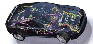
First, "Draw" the Circuit Diagram Correctly
Everything starts with the vehicle's electrical schematic diagram (Circuit Diagram). This drawing defines the logical connection relationships between over 150 Electronic Control Units (ECUs) and over 2000 electrical loads (such as sensors, actuators, motors). The core task of the design engineer is to accurately "translate" these logical relationships into physical connections.
- Precise Calculation of Wire Specifications: This is absolutely not based on empirical estimation. For a circuit powering a 60W halogen headlight, the engineer needs to calculate the theoretical current as 5A using the formula
Current(A) = Power(W) / Voltage(V). Then, they consult wire gauge standards (e.g., ISO 6722), comprehensively considering the wire's allowable temperature rise (typically no more than 20℃), voltage drop (usually required to be less than 0.5V for the entire circuit), and bundling situation within the harness (which can reduce current-carrying capacity by about 20%). Ultimately, they select the wire with the most economical cross-sectional area that meets the safety margin for that circuit, such as 1.0 mm², rather than simply using a thicker 2.5 mm² wire. This alone can save several kilograms of copper cost and weight across the entire vehicle. - Fuse and Protector Selection: Every circuit must be protected against overcurrent. For that 5A headlight circuit, the engineer will select a fuse with a rated current slightly higher than the operating current, such as 7.5A or 10A. The selection is based on strict standards including the fuse's blow characteristic (fast or slow blow), blow time under 125% overload (required to be less than 1 hour), and the requirement to blow within 2 minutes under 200% overload. The configuration of 60 to 100 fuses throughout the vehicle forms the skeleton of the vehicle's electrical safety.
Then, Place the Wires in the Correct Position
After the logical connections are correct, the next step is physical placement within the vehicle's 3D digital model. This is a game of competing for space with all other systems like the body, chassis, and interior.
- Clearance and Interference Check: This is the lifeline of design. The software performs 100% automatic scanning, checking the static clearance between the harness and over 2000 surrounding components. Regulations and standards require that the minimum dynamic clearance between the harness and moving parts (like the steering column) must be > 15mm, and the clearance from high-temperature sources (like the exhaust pipe) must be > 50mm, mandating the use of wires rated for > 120℃ or adding a 1mm thick heat shield when necessary. An undetected interference of even 2mm in the digital world could cause the wire insulation to wear through after the vehicle travels 50,000 kilometers, leading to a short circuit.
- Anchor Points and Stress Analysis: The harness cannot be placed "suspended in air." Engineers need to design an effective anchor point every 150mm to 300mm, typically using 6mm diameter plastic clips or ties. Each anchor point must withstand a pull force of at least 50N. When passing through body sheet metal holes, a rubber grommet with a thickness of <2mm must be used to prevent sharp edges from cutting the wires. The software performs stress-strain simulation, simulating scenarios where the harness is bent over 90 degrees during assembly by workers, ensuring the internal wires do not break.
Run the Entire Lifecycle with Data
Before investing in expensive molds and prototype parts, the design must pass a series of virtual tests.
- Electromagnetic Compatibility (EMC) Simulation: If a 12V power wire and a sensor wire transmitting 0-5V analog signals are routed parallel for over 200mm, fluctuations on the power wire can act like an antenna and interfere with the signal wire. EMC simulation analyzes all 5000 possible wire pair combinations. By adjusting parameters like the harness twist pitch (e.g., 30 twists per meter), adding an aluminum foil shield 0.1mm thick, or rerouting the path, the probability of interference can be reduced to below -3%.
- Durability Simulation: Simulates the effects of vibration and temperature cycling over the vehicle's 10-year lifecycle. Engineers input vibration loads from the engine with frequencies of 20-200Hz, analyzing the weakest connector terminals in the harness, predicting whether their contact resistance increase will exceed 10% after 5000 hours of vibration. Simultaneously, thermal cycle simulation models the expansion and contraction of materials over 1000 cycles between -40℃ and 120℃, checking if clip anchor points will loosen.
Cutting and Pre-processing
A fully automatic cutting and crimping machine, 12 meters long, costs over 6 million RMB. It can replace the workload of 15-20 traditional workers, increasing production efficiency by over 300%. Its task is to accurately process wire reels of over 200 specifications, totaling several kilometers in length, into over 2500 independent wires of varying lengths and terminals, laying a zero-error foundation for subsequent assembly. The first-pass yield (FPY) at this stage must reach over 99.8%; any small mistake will be magnified later, potentially leading to the scrapping of the entire harness assembly.
How Does the Machine Know How Long to Cut the Wire?
The "brain" of the fully automatic cutting machine is the processing job file from the host computer. This file contains all the instructions needed to produce one set of harnesses:
| Instruction No. | Wire ID | Cross-Section (mm²) | Color | Planned Length (mm) | Left Terminal Type | Right Terminal Type | Marking Content to Print |
|---|---|---|---|---|---|---|---|
| 0001 | 001-01 | 0.35 | BR (Brown) | 450 | AMP 1-928330-1 | - | ECU12_A15 |
| 0002 | 001-02 | 0.5 | GN/BK (Green/Black) | 1200 | DELPHI 12162184 | MOLEX 33200-0101 | SENSOR_LS |
The machine automatically selects the specified specification reel from a reel library containing over 300 reels using a robotic arm and loads it onto the feed rollers. The feed rollers, via a high-precision encoder, push the wire out to the predetermined length. High-end equipment can stably control the cutting length accuracy within ±0.5mm, ensuring no looseness or tension occurs during subsequent assembly due to uneven lengths.
Stripping is Not Simply Cutting
The purpose of stripping is to expose a certain length of copper strands for crimping. This process is completed by a set of precision blade assemblies.
- Strip Length and Precision: The strip length is strictly defined based on the terminal type and wire specification. For example, crimping a 0.5mm² USCAR terminal requires a strip length of 7.0±0.5mm. The cutting depth of the stripping blades must be precisely set to just cut through the insulation without damaging the copper strands. Damaging more than 3 copper strands is considered a non-conformance. For shielded wires, a two-step stripping process is required: first strip 3mm of the outer jacket, then reversely strip 5mm of the shield, finally leaving 8mm of the inner core insulation.
- Maintaining Strand Direction: To maintain flexibility and fatigue strength, the copper strands inside the wire are twisted together. During stripping, advanced equipment records and maintains its original twist direction (S or Z direction) to prevent the terminal from splaying at the wire root after crimping, which would affect strength.
Crimping
Crimping is the process of using mechanical force to form a firm, gas-tight connection between the terminal metal barrel and the wire conductor.
- Crimp Cross-Section Analysis: This is not simply flattening, but a precision forming process. The shape of the crimping die is specially designed to form the terminal metal into an ideal "heart-shaped" or "double-bellmouth" shape after crimping. 100% online visual inspection systems (CVI) take pictures of each crimp point and compare them to a standard cross-section diagram. Dimensions of the bellmouth, support angle, and crimp height (e.g., 0.7mm±0.03mm) are mandatory inspection items. A qualified cross-section ensures contact resistance is below 1mΩ and guarantees a pull-out force greater than 250N.
- Process Control (SPC) of Crimp Height: Crimp height is the core control parameter. Operators need to measure the crimp height using a micrometer with 1μm accuracy every 5000 crimps or every 2 hours, and input the data into the Statistical Process Control system. Once a data trend is detected outside the control limits, the machine automatically alarms and stops, preventing the production of batch defects.
Auxiliary Processes
While crimping terminals, the machine also synchronously completes some auxiliary operations:
- Pre-assembly of Marker Tubes: A 3mm diameter, 15mm long PVC marker tube is pre-threaded onto the wire at a specific location (e.g., 50mm from the terminal), laser-printed with the wire code (e.g., "ECU12_A15"), facilitating later identification by maintenance technicians. A single harness may require the installation of over 1000 marker tubes.
- Pre-assembly of Waterproof Seals: For connectors requiring waterproofing, the machine first precisely sleeves a silicone waterproof seal onto the stripped wire, and then crimps the terminal. This sequence must never be reversed, as the terminal cannot be threaded through the seal after crimping.
Equipment Maintenance and Calibration
To maintain such high precision, daily maintenance is crucial.
- Blade Life Management: Stripping blades must be replaced or resharpened after 500,000 cuts; otherwise, the stripped end will develop burrs.
- Crimping Die Maintenance: After completing 1 million crimps, crimping dies, even without visible wear, need to be sent back to the original manufacturer for precision calibration and surface coating repair to ensure stable crimp quality. A set of original crimping dies can cost as much as 20,000 RMB.
This high-speed machine can produce over 30,000 qualified pre-processed wires per 24-hour day. Its stability and precision are key to ensuring the quality and cost of the entire harness project.
Why is the Automotive Wiring Harness So Important?
The total length of the wiring harness in a modern car can reach 5 kilometers, containing over 3000 terminals, with a total weight approaching 60 kilograms. Among the vehicle's material costs, the harness ranks in the top three, accounting for 5% to 7%. For a car costing 200,000 RMB, the harness cost may exceed 10,000 RMB.
One of the most time-consuming processes on the final assembly line is wiring, with 20% of the labor hours spent on this. More critically, over 50% of electrical faults in the market originate from the wiring harness.
The Invisible Giant of Cost and Weight
In a vehicle's Bill of Materials (BOM) cost, the wiring harness consistently ranks in the top three, accounting for a high 5% to 7%. For a model with a selling price of 200,000 RMB, its harness cost may reach 10,000 to 14,000 RMB. It is not only an "invisible giant" in cost but also a "stubborn fortress" for lightweighting. The total length of a mainstream mid-size car's harness is about 3 kilometers, weighing between 25 and 30 kilograms, equivalent to dragging half a bag of cement on the road.
1. Copper Price Fluctuations Affect the Entire Industry
The core cost of the harness is metals. For every 5000 RMB fluctuation per ton in the international copper price, the impact on the per-vehicle harness cost will be a fluctuation of 100 to 150 RMB. The amount of copper used in a vehicle's harness is approximately 15 to 20 kilograms, making the raw material cost considerable.
Besides the base material, connectors are the second largest cost center. A connector that meets the high-temperature, high-vibration environment of the engine bay and has the highest IP6K9K waterproof rating can cost 5 to 8 times that of an ordinary interior connector. A vehicle has hundreds of connectors, and their cumulative cost may account for 30% of the total harness cost.
Harness design is a "war of millimeters." When engineers choose between 0.5 square millimeter and 0.75 square millimeter wire cross-sections, they need to precisely calculate current load and voltage drop. If the average cross-sectional area of the entire vehicle's harness increases by 0.1 square millimeter, the total cost may increase by 3% to 5%.
2. Harness Weight Reduction
There is a "1:100" amplification effect in automotive lightweighting: reducing the vehicle weight by 1 kilogram may save 100 liters of fuel over the entire lifecycle (based on 200,000 kilometers traveled). As one of the heaviest non-functional components in the vehicle, the harness is a main battlefield for weight reduction. The main weight reduction paths are compared below in terms of effect and challenges:
| Technology Path | Weight Reduction Effect (Estimated) | Cost Change | Technical Challenges and Notes |
|---|---|---|---|
| Aluminum Wire Replacing Copper Wire | Up to 30% | Material cost reduced by 15-20% | Connector terminals require special anti-galvanic corrosion treatment; reliability validation cycle is long. |
| 0.13 mm² Thin-Wall Wire Replacing 0.35 mm² Standard Wire | Single wire weight reduced by over 60% | Wire cost slightly increases, but saves on wrapping material. | Requires re-validation of durability; suitable for most signal transmission circuits. |
| Optimize Topology to Reduce Cable Length | Total length reduced by 10-15% | Cost decreased by 5-8% | Relies on upgrades in electrical/electronic architecture (e.g., zonal control); design difficulty is high. |
| Use High-Density/Miniaturized Connectors | Indirect weight reduction of 3-5% | Connector cost increased by 10-15% | Improves space utilization, but requires higher insertion/extraction durability for terminals. |
Taking aluminum replacing copper as an example, although it can reduce weight by 30%, aluminum's conductivity is only 60% of copper's. To achieve the same current-carrying capacity, the wire's cross-sectional area needs to be increased by 1.6 times, which partially offsets the weight reduction effect and occupies more routing space. Therefore, the current mainstream approach is to promote 0.13 mm² and even 0.08 mm² thin-wall miniaturized wires. Their performance is consistent with traditional wires in the operating environment of -40℃ to 85℃, but with obvious advantages in weight and volume.
3. Manufacturing is Labor-Intensive
Harness manufacturing is a labor-intensive industry, with an average automation rate below 20%. The cycle time for crimping a single terminal can be controlled within 3 seconds, but subsequent processes like wire routing, assembly, and tape wrapping primarily rely on skilled workers.
A harness assembly has over 3000 crimp points. Failure at any single point can lead to total vehicle function failure. Therefore, 100% electrical testing at the end of the production line is crucial. The test bench simulates the vehicle state, testing each circuit for continuity, insulation resistance (requirement ≥100MΩ), and short circuits. The entire process takes about 5-8 minutes.
Labor costs account for over 35% of the total manufacturing cost, which is the main reason why harness factories are generally located in regions with lower labor costs.
4. Repair Costs
The hidden cost of the harness is also reflected in after-sales repairs. Because the harness is buried deep within the vehicle, replacement is extremely time-consuming. Replacing a body harness in a 4S shop typically requires 8-12 labor hours, with labor costs alone potentially exceeding 3000 RMB.
If a harness problem damages expensive components like an ECU, the repair bill can easily exceed ten thousand RMB. Therefore, OEMs emphasize modularity in design, dividing the vehicle harness into 7-8 major assemblies like engine bay, instrument panel, body, door wires, enabling localized replacement and controlling the average repair time within 3 hours, thereby reducing the comprehensive cost of ownership over the lifecycle.
The Bottleneck of Electrification and Intelligence
The voltage platform has soared from 12V to 400V/800V, meaning the harness must withstand withstand voltage tests of 25-30kV, tens of times higher than traditional levels. Simultaneously, to support L3+ autonomous driving, the per-vehicle data throughput has surged from 1GB/h to 4TB/h, and transmission rate requirements have jumped from the 1Mb/s CAN bus to 10Gb/s automotive Ethernet.
This "nerve bundle" must safely carry 250kW of charging power and microvolt-level sensitive sensor signals within the same space. Its design complexity increases exponentially, and any minor flaw may directly translate into a safety risk or system performance bottleneck.
1. High-Voltage System
With voltage rising to 800V, at a current of 250A, power transmission reaches 200kW. At this point, the risk of "creepage" current increases dramatically. The insulation thickness of high-voltage cables increases from 0.3-0.5mm for low-voltage wires to 1.5-2.0mm. The material is upgraded from PVC to Cross-Linked Polyethylene (XLPE) or silicone rubber, with long-term temperature ratings increasing from 105℃ to 150℃. Any thickness variation exceeding 0.1mm or the presence of bubbles larger than 5 microns in the insulation layer can become a breakdown point under high voltage. Connector design is even more demanding, requiring protection ratings of IP6K7 (protection against powerful water jets) or even IP6K9K (protection against high-pressure, high-temperature water jets), and integration of a High-Voltage Interlock Loop (HVIL) – a safety mechanism that, within 10 milliseconds of detecting connector disconnection, notifies the system to cut off high-voltage power via a detection current change of less than 1mA.
2. Electromagnetic Compatibility
The switching frequency of an 800V system can be as high as 20kHz, generating electromagnetic interference strength tens of times that of a 12V system, with a frequency bandwidth covering from 150kHz to 2.5GHz. Autonomous driving radar operates in the 76-81GHz band, with a signal strength 100dB lower (i.e., 10 billion times weaker) than the interference signal.
This requires that high-voltage cables must have a metal braid shield with over 85% coverage, and the shield ground resistance must be less than 5 milliohms. Meanwhile, high-speed wires transmitting camera data require double-layer shielding (foil + braid) to ensure a shielding effectiveness (SE) greater than 60dB at 1GHz. During routing, high-voltage and low-voltage signal wires must maintain a distance of at least 100mm. If they must cross, they should do so at a 90-degree angle to minimize interference.
3. High-Speed Data
When the data transmission rate reaches 10Gb/s, the wire harness is no longer a simple conductor but becomes a transmission line. The signal propagation speed within it approaches the speed of light (approx. 2x10^8 m/s), with a very short wavelength. At this point, the characteristic impedance of the harness (typically required to be 100Ω±10%) becomes the primary indicator.
To maintain stable impedance, the two wires of a differential pair (e.g., USB, Ethernet) must be strictly kept equal in length, with the length difference controlled within 1mm (corresponding to a signal delay of about 5 picoseconds); otherwise, signal distortion occurs. The bending radius of the harness cannot be less than 5 times the wire diameter; excessive bending will change the characteristic impedance, causing signal reflection. The terminal arrangement inside the connector must also simulate the transmission line structure on a PCB, with impedance discontinuity points not exceeding ±15%.
4. Heat Dissipation and Power Density
During 500A DC fast charging, even if the wire resistance is only 0.1mΩ, according to the formula P=I²R, the heat generation power per meter of harness can be as high as 25W. The harness is no longer a cold component but a heat source. To ensure the temperature does not exceed the 150℃ limit of the insulation layer, besides increasing the cross-sectional area (e.g., using 95 square millimeter cables), active cooling solutions are needed. The current mainstream solution is liquid-cooled charging guns, where coolant circulates inside the cable to remove heat, allowing the cable's outer diameter to be controlled around 28mm. If passive air cooling were used, the cable outer diameter for the same current-carrying capacity would exceed 45mm, drastically increasing weight and installation difficulty.
5. Architectural Change
The traditional distributed architecture leads to an astonishing total harness length. To solve this problem, the industry is moving towards a Zonal Architecture. It divides the vehicle into 5-7 physical zones (e.g., Left Front, Right Front, Left Rear, Right Rear, Central), with a Zone Control Unit (ZCU) in each zone.
Most actuators and sensors connect locally to the ZCU, requiring only a high-speed Ethernet backbone to connect the ZCUs. This change can reduce the total harness length by 30% (from 5 km to 3.5 km), decrease weight by 20% (from 60 kg to 48 kg), and reduce the number of connectors by 40%. The challenge, however, is that the ZCU needs to integrate and process I/O interfaces for over 50 different protocols, making its complexity and cost far higher than traditional single-function ECUs.
6. Testing and Validation
Traditional harness testing only checked for continuity, insulation, and shorts. Now, the test items have significantly increased:
- High-Speed Signal Integrity Testing: Uses a Vector Network Analyzer (VNA) to measure if the -3dB bandwidth is greater than 10GHz and if the return loss (S11) is less than -15dB.
- EMC Pre-compliance Testing: Conducts Radiated Emission (RE) and Radiated Immunity (RI) tests in an anechoic chamber to ensure compliance with standards like CISPR 25.
- High-Voltage Endurance Testing: Simulates the vehicle's lifecycle (15 years or 300,000 km) of vibration and thermal cycling (-40℃ to 125℃, 5000 cycles), followed by a withstand voltage test of 2500V AC for 1 minute.
integrated electrical networks combining wires, connectors, and terminals. Manufacturing uses automated crimping (±0.1mm precision) and multimeter continuity tests, outputting 20-30 units/hour.
