What Is Cable and Harness Assembly
Cable and harness assembly involves bundling insulated wires (22–28 AWG) with connectors, terminals, and protective sleeves, following IPC/WHMA-A-620. Steps include stripping, crimping, and testing continuity (≤0.1Ω resistance) to ensure reliable power/data transmission in automotive or aerospace applications.
Wires, Cables, and Connectors
A typical commercial harness might incorporate over 100 individual wires, ranging from fine 28-AWG signal lines carrying milliamps to robust 12-AWG power conductors handling 15 amps or more. The selection directly impacts performance, safety, and cost. For instance, opting for tin-plated copper over bare copper can improve corrosion resistance, adding roughly 0.50 plastic header to a $25.00 sealed, multi-pin military-spec unit capable of withstanding 500 mating cycles and exposure to 100% humidity. Understanding these building blocks is the first step in designing a robust and reliable assembly.
A lower AWG number means a thicker conductor; a jump from 24 AWG (0.51 mm²) to 20 AWG (0.82 mm²) reduces electrical resistance by approximately 40%, allowing for higher current carry or less voltage drop over distance. For example, a 10-foot 20 AWG wire powering a 2-amp sensor will experience a negligible 0.1-volt drop, while a thinner 24 AWG wire would see a 0.25-volt drop, which could be critical for precision analog devices. Insulation material is another critical choice. Common PVC (Polyvinyl Chloride) is cost-effective, rated for temperatures up to 80°C (176°F), and costs around $0.15 per meter. For higher heat environments near engines or industrial machinery, Cross-linked Polyethylene (XLPE) or Teflon (FEP) is used, withstanding 125°C to 200°C (257°F to 392°F) but increasing material cost by 300% or more.
The AWG standard is logarithmic; moving three gauges (e.g., from 24 to 21 AWG) halves the resistance, directly impacting power efficiency.
A standard 4-conductor shielded cable for data transmission might have a 24 AWG twisted pair for signals, a drain wire for grounding the foil shield, and two 20 AWG conductors for power, all within a 5 mm diameter jacket. This consolidation protects against Electromagnetic Interference (EMI), which can corrupt signals operating at frequencies above 100 MHz. The shielding itself, typically a braided copper mesh or aluminized Mylar foil, adds 15-20% to the cable's cost and weight but is essential for signal integrity in applications like automotive sensors or medical equipment.
A basic 2.54 mm pitch pin header might be rated for 3 amps per pin and 250 volts, suitable for low-power internal board connections. In contrast, an automotive connector like a USCAR-type will feature a TPA (Terminal Position Assurance) clip and a CPA (Connector Position Assurance) latch to prevent vibration-induced disconnection. Its gold-plated contacts may be rated for 10,000 insertion cycles and have an IP67 rating, meaning it must be completely dust-tight and withstand immersion in 1 meter of water for 30 minutes. The plating thickness, often 0.76 microns (30 microinches),ensures a stable, low-resistance connection of less than 5 milliohms over the vehicle's 15-year lifespan.
Planning the Assembly Layout
A well-planned layout can reduce assembly time by 25% and cut material waste by up to 15%, directly impacting the bottom line. This stage involves creating a detailed schematic and a 1:1 scale drawing that dictates the exact length of each wire, bend radii, and the precise location of every tie and clamp. For a complex harness with 150 wires, this planning might take 40-50 engineering hours, but it prevents costly errors during production, where a single misrouted wire can lead to a $5,000+ field failure in an automotive or aerospace application. The goal is to balance electrical requirements with physical constraints, ensuring the bundle fits within its designated 15 mm x 35 mm channel while withstanding 10 Gs of vibration and temperatures from -40°C to 105°C.
For a 2-meter long industrial machinery harness, the pin board is a 2.2 m x 1.2 m sheet of plywood or aluminum, drilled with 50+ metal studs and hooks that correspond to the harness's branch points and connectors. The layout must account for service loops, adding an extra 50-75 mm at connection points to allow for 2-3 re-terminations over the product's 20-year service life. A critical, often overlooked, detail is the minimum bend radius. For a bundle of 12 wires with a total diameter of 10 mm, the bend radius should be no less than 20 mm; bending it tighter risks damaging insulation and compromising the wires' 35-pound tensile strength.
| Layout Consideration | Typical Value or Specification | Impact of Deviation |
|---|---|---|
| Wire Length Tolerance | +50 mm / -0 mm | Short wires are scrap; excess length increases cost and weight. |
| Bundle Bend Radius | 4x Bundle Diameter | Sharp bends (<2x diameter) stress conductors, leading to premature failure. |
| Service Loop Length | 75 mm | Insufficient length makes field repairs difficult or impossible. |
| Clamp Spacing | Every 300 mm | Spacing >400 mm allows harness whip and chafing under vibration. |
Wires running through a high-vibration area like an engine compartment must be routed away from hot surfaces (>120°C) and sharp edges by at least 25 mm. Any point where the harness passes through a metal bulkhead requires a grommet rated for the specific IP67 environmental seal, adding 3.00 per pass-through but preventing $20,000+ water damage claims. The planning must also sequence the assembly. Installing a 3.5 mm diameter convoluted tubing over a 50-wire bundle is impossible after connectors are attached; the tubing must be slid on first. This process planning reduces installer backtracking, shaving 15-20 seconds per operation, which saves over 30 minutes per harness.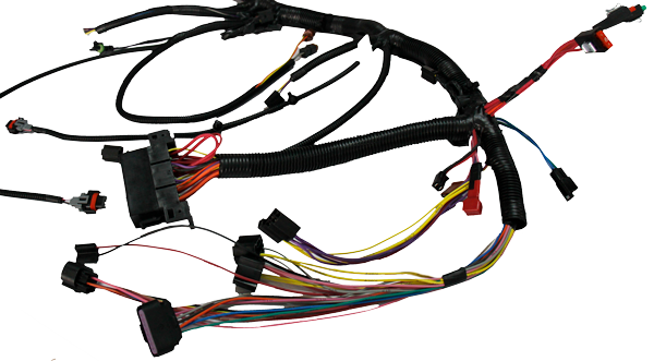
Cutting and Stripping Wires
An error of just 1 mm in strip length can cause a faulty crimp, leading to a 40% increase in resistance at the terminal and potential overheating. Modern automated wire processing machines can achieve astonishing accuracy, cutting 2,500 wires per hour with a length tolerance of ±0.5 mm and stripping both ends simultaneously. For a high-volume manufacturer, investing in a $45,000 automated machine pays for itself in under 14 months by reducing manual labor and material scrap by up to 18%. The process is far more nuanced than it appears; stripping a 20 AWG Teflon-insulated wire requires a different blade setting and force than stripping a 10 AWG PVC wire, and getting it wrong can nick the conductor, reducing its pull strength by 50% and creating a point of failure.
The first critical setting is blade depth, which must be calibrated to within 0.05 mm to cleanly remove insulation without damaging the copper strands. For a standard UL 1007 16 AWG wire with 0.06 mm thick PVC insulation, the blade must penetrate 0.15 mm into the insulation. Cutting too deep will sever up to 15% of the fine 19/30 stranding, drastically reducing the wire's current-carrying capacity and its 15-pound tensile strength. The strip length is equally crucial. For a standard open-barrel terminal, the ideal strip length is 2.5 mm. A 3.0 mm strip exposes bare copper, risking a short circuit, while a 2.0 mm strip results in an unreliable crimp that fails pull tests requiring 35 Newtons of force.
| Wire Type / Gauge | Insulation Thickness | Typical Strip Length | Blade Depth Setting | Nick Depth Allowance |
|---|---|---|---|---|
| 22 AWG PVC (UL1061) | 0.25 mm | 2.3 mm | 0.30 mm | <0.05 mm |
| 16 AWG XLPE | 0.80 mm | 3.5 mm | 0.95 mm | <0.08 mm |
| 20 AWG Teflon | 0.20 mm | 2.5 mm | 0.25 mm | <0.03 mm |
A rotary blade system uses two counter-rotating blades that close around the wire at a precise 45-degree angle and complete a 180-degree rotation in 120 milliseconds to cleanly cut the insulation. The machine must then retract the insulation with a force of 8-10 pounds without stretching or deforming the conductor. For shielded wires, a non-rotating laser stripping system is often used. It focuses a 20-watt CO2 laser onto a 0.3 mm diameter area to ablate the outer jacket without touching the delicate 95% coverage braided shield underneath. This process is slower, at 400 strips per hour, but eliminates any mechanical damage to the shield, which is critical for maintaining EMI immunity in data lines carrying 100 MHz+ signals.
Nylon insulation, which absorbs moisture, can become more ductile in a 60% humidity environment, requiring a 10% reduction in blade force to achieve a clean cut. After stripping, the process must be validated. A go/no-go gauge checks strip length to within ±0.1 mm, and a 200x magnification microscope inspection checks for nicks. Finding more than 2 nicks per 1,000 strips triggers a blade change. This relentless focus on precision in these first mechanical steps prevents downstream failures, ensuring that every termination has the best possible chance of lasting for the product's entire 10,000-hour operational life.
Attaching Terminals and Connectors
A single poorly crimped terminal in a 200-pin aerospace connector can necessitate a 50,000+ teardown and rework of an entire assembly. Modern automated crimping machines apply 2,000 Newtons of force with a precision of ±0.02mm to form a connection that has less than 0.5 milliohms of resistance and can withstand 15 pounds of pull force. The cost of these machines ranges from $15,000 for a benchtop unit to $85,000 for a fully automated system, but they eliminate human error and reduce scrap rates from 5% to under 0.1%, paying back in under 18 months for a medium-volume production line.
The process begins with the absolute necessity of tooling calibration. A crimp press must be validated every 4 hours of operation using a certified calibration gauge to ensure the crimp height is within the terminal manufacturer's specified tolerance, often ±0.05 mm. For a 0.64 mm wide open-barrel terminal for 22 AWG wire, the target crimp height might be 0.90 mm. A crimp that is 0.10 mm too tight will over-compress the wire, breaking strands and increasing resistance; a crimp 0.10 mm too loose will result in 40% less contact area and a connection that will vibrate loose.
- Wire Preparation: The stripped wire must be pristine. For a 19-strand copper conductor, not a single strand can be missing or nicked. The strip length must be exact to 2.5 mm ±0.2 mm so that the conductor barrel grips the insulation and the wire barrel grips only the conductor, creating a strain relief.
- Terminal Selection: The terminal must be matched to the wire gauge and the application's current load. A 16 AWG terminal crimped onto an 18 AWG wire will have 30% less contact surface area, leading to hotspots at 15 amps of current. The plating matters immensely: 0.76 µm (30 µin) of gold plating is standard for low-energy signals, while 3 µm of tin plating is sufficient for 10-amp power circuits.
- The Crimp Itself: The crimp die must be the exact match for the terminal. The machine is programmed for the correct anvil-to-ram distance and crimp force. The crimp profile is not a simple crush; it forms a series of F-shaped indentations that fold the metal into the wire, creating a 10,000 PSI bond. A cross-section of a perfect crimp will show zero air pockets and all wire strands flowing uniformly within the terminal barrel.
- Connector Assembly: Inserting the terminated wire into the connector housing requires another layer of precision. The terminal must audibly click into place, engaging the primary lock. A CPA (Connector Position Assurance) clip is then snapped in, adding a secondary lock. For a 12-circuit connector, the insertion force for each terminal is about 5 Newtons, and the complete connector mating requires 45 Newtons of force.
Every crimped terminal must pass a destructive pull test on a 1% sample basis. A 20 AWG terminal must consistently withstand a 35 Newton (8-pound) force for 15 seconds. Furthermore, a micro-ohmmeter is used to measure voltage drop; a good crimp will show less than 5 millivolts of drop at a 5-amp test current.
Grouping and Securing Wires
A poorly secured bundle in an automotive application can lead to chafing failure within 1,000 hours of operation in an environment with 10 Hz to 2,000 Hz random vibration. Using the correct materials and techniques can reduce harness weight by 12%, lower assembly time by 20%, and drastically cut warranty claims. For a 150-wire harness spanning 3 meters, this involves selecting from over 20 different securing products, each with specific cost and performance trade-offs, from a 4.00 aerospace-grade heat shrink clamp.
The methodology for bundling is governed by a strict set of physical and electrical rules that must be adhered to for a reliable outcome.
- Separation of Power and Signal: 120-volt AC power lines carrying 15 amps must be bundled separately from low-voltage (5V) sensor lines carrying 5 mA signals. The 50/60 Hz electromagnetic field from the power wires can induce a 120 mV noise signal into adjacent sensor wiring, corrupting data transmission. A minimum separation of 25 mm between bundles is a standard rule to mitigate this interference.
- Bundle Diameter Management: The goal is to create a uniform, round bundle. A haphazardly packed harness can have a 35% larger cross-sectional area, making it unable to fit through a designated 15 mm grommeted hole. For a subset of 22 wires with an average diameter of 0.9 mm, the theoretical minimum diameter is ~8.5 mm. In practice, with packing efficiency and tape, the final bundle diameter will be 11.5 mm.
- Tie and Clamp Spacing: The maximum distance between securing points is determined by the harness's weight and the application's vibration profile. For a 1.2 kg/m harness, ties or clamps are typically placed every 300 mm. Increasing this spacing to 400 mm allows the harness to deflect excessively under vibration, leading to fatigue failure at connection points within 5,000 operating hours.
A standard 4.8 mm wide by 200 mm long nylon 6/6 tie has a 50-pound tensile strength and a continuous service temperature of -40°C to 85°C. For engine bay applications, a stainless steel P-clamp with a 15 mm diameter mounting hole and an 18-pound load capacity is used, secured by a M6 bolt torqued to 8 Nm. For organizing branches, fleece-backed vinyl harness tape is applied with a 50% overlap per wrap, providing abrasion resistance and allowing for a clean, professional look. In high-heat areas exceeding 125°C, fiberglass sleeving or corrugated conduit with a UL 94 V-0 flame rating is slid over the bundle before termination, adding $1.50 per foot to the harness cost but preventing insulation melt-through.
Testing the Finished Assembly
A 100% test regimen on a 550 aircraft engine harness might add $35 to its production cost, but this pales in comparison to the $15,000+ cost of removing and replacing it after installation. Modern automated test systems can perform 500-point electrical validation in under 90 seconds, checking for continuity, insulation defects, and even specific wire routing within a connector. For a high-volume automotive supplier, a $250,000 investment in such a system can prevent over $2.5 million annually in potential recall costs and protect its brand reputation from the severe impact of a safety-related recall.
| Test Type | Key Parameters / Specifications | Consequence of Failure |
|---|---|---|
| Continuity Test (Low Current) | 30 mA, 100 ms pulse, < 50 mΩ resistance | False pass on high-resistance crimp. |
| Insulation Resistance (IR) Test | 500 VDC, 100 MΩ minimum @ 25°C/50% RH | Undetected insulation nick leading to arc-over. |
| Dielectric Withstanding Voltage (Hi-Pot) | 1,500 VAC, 60 Hz, 60 s duration, < 2 mA leakage | Catastrophic in-field short circuit. |
| Four-Wire Kelvin (Crimp Resistance) | 1A DC, measure ΔV, calculate R < 5 mΩ | Overheating and connection failure under load. |
A low-current (< 100 mA) signal is sent down each circuit to verify that the electrical path is unbroken and connected to the correct pins. This test catches opens (a broken wire or missed crimp) and shorts (two wires touching where they shouldn't be). However, it can miss a high-resistance crimp that may pass a low current but fail under a 10-amp load. This is why a four-wire Kelvin test is essential for power circuits. It applies a higher 1-amp current and precisely measures the voltage drop across each termination, calculating resistance to within 0.01 mΩ. A good crimp will measure under 2 mΩ; anything above 5 mΩ is rejected, as it would generate 5 watts of waste heat at 10 amps (P=I²R).
The Insulation Resistance (IR) test applies 500 VDC between a conductor and all other conductors bundled with it. The meter measures the tiny amount of current that leaks through the insulation, calculating a resistance value. A reading below the 100 MΩ minimum indicates an insulation flaw, such as a nearly invisible nick from stripping or a flaw in the material. This is followed by the Dielectric Withstanding Voltage (Hi-Pot) test, a stress test that applies a high voltage—1,500 VAC for a 120V-rated harness—for 60 seconds. This test is designed to find weaknesses that could break down over time; it should not be used to find gross defects, as it can actually damage good insulation if over-applied. Any leakage current exceeding 2.0 mA causes an immediate failure.
A cable harness assembly integrates wires, cables, and connectors via structured steps: planning layouts with 0.1mm precision, cutting wires to ±0.5mm tolerance, stripping insulation uniformly, crimping terminals at 6-8N force, grouping with zip-ties every 150mm, and testing via 100-250V continuity checks for reliability.
