What is the Difference Between Prototype and Production Harness Assembly
Prototype harnesses are hand-assembled for R&D, using off-the-shelf parts with ±1mm tolerances and basic tests. Production employs automated tooling (e.g., 70% crimping automated), custom connectors, strict ±0.5mm specs, and 100% electrical testing for mass consistency and reliability.
From Design to Real-World Use
A 2023 study by the Center for Automotive Research found that over 70% of electrical issues in new product designs are only discovered when the first prototype harness is installed in the actual assembly. This stage answers critical questions: Does a 150mm cable length actuallyreach the sensor, or is 152mm the realistic minimum? Does a bundle of eight 20-gauge wires fit through a 10mm gap in the chassis without pinching? Engineers typically build 3 to 5 prototype units, each costing 5 to 20 times more than the future production version due to manual labor and premium-priced components.
The "Build-to-Test" Mentality
A single, complex prototype harness can require 40-80 person-hours of skilled labor to assemble, compared to a 15-25 minute cycle time on a fully optimized production line. This intensive process is justified because it uncovers approximately 80% of potential design and integration flaws that are invisible in a digital model.
Prototype assembly is an advanced form of debugging. It's the process of finding out why the perfect world of CAD doesn't work in the imperfect world of physical materials and assemblies.
A technician gathers materials based on the engineering bill of materials (BOM), but with key differences from production:
-
Component Sourcing: Instead of bulk reels from a primary supplier, components are sourced from distributors like Digi-Key or Mouser.
-
Intentional Overlength: Wires are rarely cut to their final, theoretical length. Technicians are instructed to cut wires +100mm to +150mm longer than the CAD model specifies. This extra length is a "budget" for rerouting during physical installation trials. For a harness with 50 wires, this can mean an extra 5-7.5 meters of wire used solely for experimentation.
-
Manual Documentation: Each step is documented with photos, notes, and often redlined drawings. A single harness build can generate 50-100 annotated images highlighting interference points, difficult connector mating sequences, and strain on wires.
The actual assembly is a iterative loop of fit, form, and function checking. The technician builds sub-assemblies, test-fits them in a prototype unit or on a soft tooling board, and makes adjustments in real-time.
|
Characteristic |
Prototype ("Build-to-Test") |
Production ("Build-to-Sell") |
|---|---|---|
|
Primary Goal |
Validate design, discover flaws |
Maximize throughput and consistency |
|
Build Time |
40-80 hours per harness |
15-25 minutes per harness |
|
Wire Cutting |
Manual, with ±2mm tolerance; lengths adjusted on-the-fly |
Automated machine, ±0.5mm tolerance; fixed lengths |
|
Crimping Quality |
Validated by technician feel and micro-section analysis of 1 in 10 samples |
Validated by automated Crimp Force Monitoring (CFM) on 100% of crimps |
|
Change Frequency |
Constant; 5-15 engineering change orders (ECOs) are expected and incorporated |
Highly controlled; changes require line re-validation and are batched |
The testing regimen on these first articles is exhaustive and destructive in nature. It's designed to simulate years of wear and extreme conditions in a compressed timeframe. Key tests include:
-
Electrical Validation: A 100% connectivity and hi-pot (dielectric withstand) test is the baseline. This checks for shorts (less than 1 MΩ resistance where there should be infinity) and opens (less than 0.5 Ω resistance where there should be continuity).
-
Mechanical Stress Testing: The harness is subjected to vibration profiles on a shaker table. A common test might simulate 10 years of vehicle vibration in a 200-hour test, monitoring for wire fatigue at flex points.
-
Environmental Cycling: Units are placed in thermal chambers cycling from -40°C to 125°C for hundreds of cycles to test the integrity of insulation, seals, and connector retention.
-
Destructive Analysis: At least one prototype unit is dissected. Connector crimps are potted in epoxy and cross-sectioned ("micro-sectioned") to measure parameters like the compression ratio (typically targeted at ~85%) and the amount of wire strand flash extruded in front of the crimp barrel (ideally 0.5mm - 1.5mm).
Testing Under Real-World Conditions
A major automotive OEM estimates that this phase identifies over 90% of potential warranty issues, with each discovered failure representing a potential saving of 500 in warranty costs per vehicle incident, multiplied across thousands of units.
We aren't testing to see if it works now; we're testing to predict how and when it will fail later.
The testing regimen is a multi-stage assault on the prototype, designed to probe every conceivable weakness. The following table outlines the core pillars of this evaluation:
|
Test Pillar |
Objective |
Key Metrics & Standards |
Simulated Real-World Condition |
|---|---|---|---|
|
Electrical & Environmental |
Validate signal integrity and insulation resilience under extreme conditions. |
ISO 16750-4: Voltage drop (< 100mV at 10A), Insulation Resistance (> 100 MΩ), Hi-Pot ( 500V AC for 60s). |
Engine bay temperatures cycling from -40°C to 125°C while electrically loaded. |
|
Mechanical Durability |
Assess physical endurance against vibration, flex, and abrasion. |
ISO 20653: IP6K9K dust/water ingress; Vibration per SAE J2380 (random vibration, 50Hz-2000Hz). |
100,000 door slams on a door harness; engine vibration for 250,000 miles. |
|
Chemical & Thermal Aging |
Ensure material integrity when exposed to fluids and long-term heat. |
SAE J2260 (thermal aging); Exposure to 5% saline solution, engine oil, brake fluid. |
15-year exposure to road salts and under-hood fluid spills. |
After a 100% circuit verification, the harness undergoes a dielectric withstand test, often called a "hi-pot" test, where a high voltage—typically 500 Volts AC or 1500 Volts DC—is applied between wires and the shield for 60 seconds to ensure the insulation can withstand voltage transients from the vehicle's electrical system. The real test begins inside a thermal chamber. Here, the harness is subjected to 1,000 cycles between -40°C and 85°C while powered.
-
Intermittent Opens: A poorly executed crimp that loses connection at extreme temperatures.
-
Insulation Cracking: Stiff insulation that becomes brittle and cracks at low temperatures.
-
Seal Failure: Connector seals that lose elasticity, allowing moisture ingress.
A standard test might compress 10 years of vibration into a 200-hour regimen. Simultaneously, technicians perform "wiggle tests" by manually stressing connections at the connector and splice points while monitoring electrical signals for interruptions, identifying potential micro-fretting—a phenomenon where tiny vibrations cause microscopic wear on terminal surfaces, leading to increased resistance over time. For harnesses in dynamic areas, like those in doors or steering columns, a flex test is critical. A test machine might bend a section of the harness 50,000 times at a rate of 20 cycles per minute through a 90-degree arc to simulate a lifetime of use.
Bridging to Manufacturing
The hand-built prototypes, which may have undergone 15-20 engineering revisions, serve as the physical master from which all production tooling and instructions are derived. The primary output is the "Manufacturing Bill of Materials" (MBOM) and a complete set of "Build-to-Print" documentation, which differ significantly from their prototype-phase predecessors. The MBOM shifts from specifying "1x connector, supplier A" to specifying the exact manufacturer part number, the cavity position within the injection molding tool (e.g., Tool #AST-245, Cavity 7), and the supplier's quality acceptance criteria, such as a Critical-to-Function (CTF) dimension with a tolerance of ±0.15mm.
The goal of the bridge is to translate the 'tribal knowledge' of the prototype technician into foolproof instructions for a production line operator.
The creation of production-grade tooling is a capital-intensive but essential step. The soft, 3D-printed or machined aluminum fixtures used for prototype assembly are replaced with hard-coated steel production boards. These boards, costing 50,000 each, are engineered with poka-yoke (error-proofing) features. For example, a connector receptacle will only fit on the board in one orientation, and a missing terminal will prevent the machine from proceeding. The wire processing lines are programmed with the finalized lengths and strip lengths. A single automated machine can cut, strip, and mark 1,200 wires per hour with a precision of ±0.5mm, a task that would take a technician an entire week. The data from prototype pull-force testing (e.g., a terminal must withstand 50 Newtons of withdrawal force) is used to set up Crimp Force Monitoring (CFM) systems on production presses. These systems analyze the force-over-distance curve of each crimp in real-time, rejecting any that deviate from the "golden profile" with 99.9% accuracy, a process far more reliable than the destructive micro-sectioning of 1 in 100 samples used in prototyping.
Furthermore, the transition plan includes a rigorous Process Failure Mode and Effects Analysis (PFMEA). This live document uses the failure data from the prototype Design Verification Plan & Report (DVP&R) to proactively score and mitigate risks on the production line. For instance, if prototype testing revealed chafing at a specific grommet, the PFMEA would rate this as a high-risk item. The mitigation would be to design an automated vision system that uses a camera to verify 100% of harnesses are correctly seated in that grommet before the assembly leaves the station. This direct feedback loop from physical test failure to automated production quality control is the ultimate expression of "bridging to manufacturing," ensuring that the 0.1% failure rate observed in the lab is driven to < 50 defects per million (DPM) in mass production.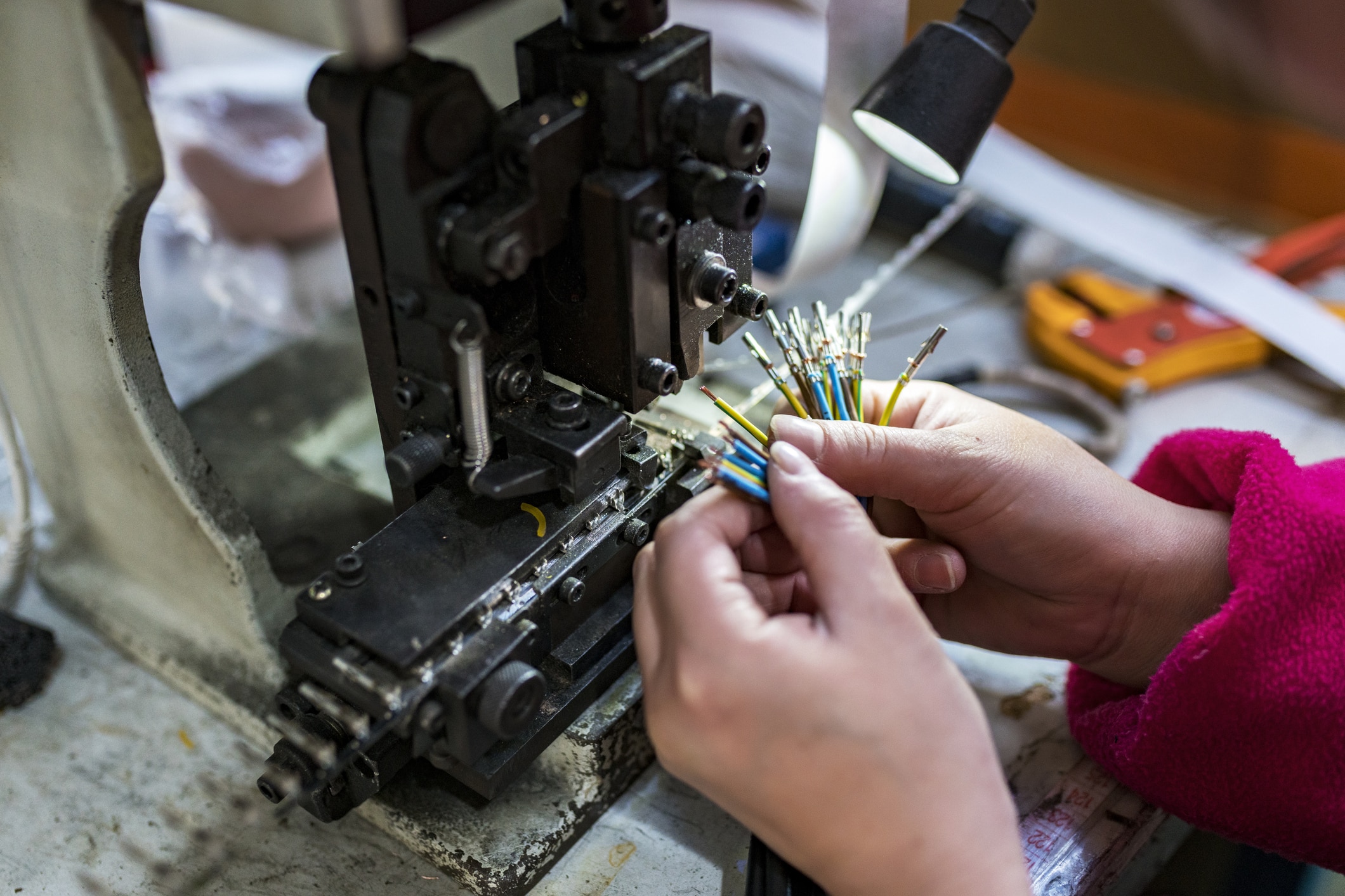
Build Process: Handcrafted vs. Streamlined
A skilled technician might build a single, complex harness in 3-5 days, incorporating 15-20 engineering change orders (ECOs) on the fly. In contrast, the production phase is optimized for repeatability and cost control. The goal is to reduce the assembly time for that same harness to under 45 minutes per unit with an error rate approaching 0.1%. This section breaks down the critical differences in how these harnesses are physically built.
Handcrafted: The Art of the Prototype
Prototype harness assembly is a discipline of managed improvisation, where the primary metrics are flexibility and proof-of-function, rather than speed and cost. It's a resource-intensive process tailored to navigate the inherent uncertainties of a product's early life. The environment is more akin to a research lab than a factory floor, characterized by rapid iteration and highly skilled problem-solving.
The Core Team and Economic Reality
A prototype build is typically executed by a very small cell of 1-3 highly skilled technicians, each often possessing 10+ years of experience. This expertise commands a premium labor rate, typically between 75 per hour.
|
Aspect |
Prototype Realities |
Production Comparison |
|---|---|---|
|
Team Size |
1-3 highly skilled technicians |
20-50+ operators on a line |
|
Build Time |
3-5 days for a complex harness |
30-60 minutes per unit |
|
Primary Goal |
Functional Validation & Design Iteration |
Consistency & Cost-Efficiency |
|
Documentation |
Living schematics, >10 ECOs common |
Fixed Standard Work Instructions (SWI) |
Tools of the Trade: Versatility Over Speed
You won't find $50,000 automated crimping machines here. Instead, the toolkit is built around flexibility:
-
Manual Pneumatic Crimpers: Adjustable with a dial to handle 22 AWG to 10 AWG wires, with changeable die sets. A technician might perform 200-300 crimps per harness, each potentially with a different terminal.
-
Universal Tooling: A single heat gun with multiple nozzles replaces a production line's dedicated tunnel ovens for heat shrink. A hand-held pin insertion tool is used instead of a fully automated, force-monitored press.
-
The Formboard: The "assembly line" is often a 4' x 8' sheet of plywood or MDF, with a full-scale 1:1 drawing of the harness taped to it.
The prototype bench is a lesson in resourcefulness. Its most important tool is not a physical object, but the technician's ability to solve unforeseen problems with whatever is on hand.
The Fluid Process: Embracing Change
The build process is non-linear and iterative. It's common for a technician to incorporate 2-3 significant Engineering Change Orders (ECOs) during the 5-day build cycle. A single change might involve:
-
Swapping a connector due to a newly discovered sourcing issue (a 30-minute delay to find a substitute).
-
Adding three new sensor wires to the schematic (requiring ~45 minutes to cut, strip, label, and route the additional wires).
-
Increasing the wire gauge from 20 AWG to 16 AWG for a power branch after initial calculations showed excessive voltage drop (invalidating 15 previously made crimps and adding 1 hour of rework).
Wires are pulled from a 100-spool rack, and connectors are taken from small bins. There is no formal kitting. The technician spends a significant portion of their time, roughly 15-20%, simply gathering components for the day's work.
Streamlined: The Science of Production
When a product moves from prototype to mass production, the harness assembly process undergoes a transformation from a craft into a precise engineering discipline. The focus shifts radically from flexibility to repeatability, and from validating a design to optimizing for cost, speed, and consistency. This phase is characterized by significant upfront capital investment in tooling and processes, all aimed at achieving marginal gains that compound over production runs of 10,000, 100,000, or even 1,000,000+ units.
A line might involve 15-25 operators, each performing a specialized, repetitive task. The layout is designed to minimize wasted movement; the goal is to reduce an operator's reach for any component to under 30 centimeters. The entire line is balanced to a Takt Time—the maximum allowable time to complete a process to meet customer demand. For a complex automotive harness, this might be set at 45 minutes per station. If one station consistently takes 50 minutes, it creates a bottleneck that stalls the entire line, making its efficiency paramount.
The investment in production is manifested in its specialized, often single-purpose, equipment. This is where the per-unit cost is driven down through speed and accuracy.
-
Automated Cutting/Stripping Machines: These machines process wires from large 500kg spools at astonishing speeds. They can cut and strip a wire to a precise length of 1.5 meters in under 3 seconds, with a length tolerance of ±1.0 mm. A single machine can output over 1,200 wires per hour, each end stripped to an exact length, ready for terminal application.
-
Fully Automatic Crimping Presses: Replacing the adjustable hand tool, these presses are programmed for specific wire-terminal combinations. They are poka-yoke (error-proofed); the machine will not cycle if a 16 AWG wire is inserted into a die set for a 20 AWG terminal. More importantly, they perform 100% crimp quality monitoring, measuring the force required for crimping in real-time and rejecting any crimp that falls outside a pre-defined statistical process control (SPC) window. This real-time data collection can flag tooling wear long before it creates a defective part.
-
The Formboard Fixture: The plywood sheet is replaced by a massive, custom-built 3D formboard, often made of steel and aluminum, costing 40,000. This fixture is a physical negative of the product's wire paths, with dedicated clamps, connector holders, and breakout points. It ensures that every harness is 100% geometrically identical, which is critical for trouble-free installation on the final assembly line.
Every action on the production line is dictated by a Standard Work Instruction (SWI). This document is the law. It contains not just steps, but critical, quantified specifications:
-
Torque: "Tighten connector XYZ's mounting screw to 4.5 Nm ± 0.3 Nm."
-
Force: "Seal plug insertion requires a force between 25-40 Newtons."
-
Sequence: "Install sub-assembly A before routing wire group B to prevent pinching."
An operator might perform an in-process continuity test after completing a section, and every finished harness undergoes a 100% electrical test on a custom-built test fixture that simulates the final product, checking for shorts, opens, and miswires in under 60 seconds. This data-driven, highly controlled environment is what enables a manufacturer to confidently produce 5,000 flawless harnesses per week, each one a perfect replica of the prototype that started it all.
