What Makes a Good Cable Harness Assembly
A good cable harness uses UL-certified wires (22-18 AWG), precision crimping (±0.05mm tolerance) with IP67 connectors, and undergoes 100% electrical testing (insulation resistance ≥100MΩ) for automotive/industrial reliability.
Reasonable Design Planning
A German automaker once selected 0.75mm² wires (rated for 8A) to carry a 10A power supply in the main harness, causing the wires to overheat and melt, leading to a recall of 110,000 SUVs with a single-unit repair cost exceeding 800 euros. Another new energy vehicle manufacturer's signal harness lacked shielding; electromagnetic interference during high-speed driving caused the vehicle's infotainment system's bit error rate to soar from 1e-9 to 1e-6, resulting in 2300 complaints per month.
Good harness design isn't about drawing pretty pictures; it's about turning the parameters of each component and the constraints of each path into "quantifiable, verifiable" hard rules. A 1mm difference in bending radius can result in a 10x difference in wire lifespan; a 0.1mΩ difference in contact resistance can cut the terminal burnout time in half.
Electrical Performance Matching
Last year, a new EV maker delivered pure electric SUVs; within 3 months of delivery, over 2000 units experienced "instrument cluster black screen during charging." Disassembly revealed that the fast-charging harness used 0.75mm² power wires (rated for 8A), but the actual fast-charging peak current was 15A. The wires continuously overheated, the insulation melted after 10 charging cycles, and the positive and negative terminals shorted to ground.
At an industrial robot factory, a six-axis robotic arm consistently misreported position signals during high-speed rotation during debugging. Investigating the harness revealed that the encoder signal wire used unshielded twisted pair cable, laid parallel to the motor power cable for 500mm. Electromagnetic coupling caused signal voltage fluctuations of ±0.5V (normal ±0.1V), leading the PLC to misinterpret excessive position deviation beyond the threshold.
Harness design isn't just "matching a wire"; it's about calculating the current for each wire, the interference per meter, and the resistance of each connection point with a calculator. After all, a 0.1mm² difference in cross-sectional area can mean a 3-year difference in wire lifespan, and a 5mm difference in wire spacing can cause the signal error rate to increase tenfold.
Power Wires: Cross-section isn't about choosing bigger, but calculating "just enough to handle continuous + peak current"
For example, a car's windshield wiper motor specification states "operating current 5A, starting peak current 30A, lasting 3 seconds."
Checking the UL1581 standard, the current-carrying curve for a 1.0mm² PVC wire (105°C rating) shows: at 30A current, the temperature rises to 85°C in 10 seconds (insulation melting point 120°C, safety margin 35°C). If a cheaper 0.75mm² wire of the same specification is chosen, under the same 30A/10s condition, the temperature surges to 112°C, the insulation softens and deforms, and after 3 months it will crack due to repeated thermal expansion and contraction, increasing the risk of leakage current by 40%.
It's even more extreme for new energy vehicle battery pack sense wires – each sense wire measures the voltage of 12 battery cells, with a continuous current of 0.5A, but the BMS sampling causes a transient current of 1A. One manufacturer initially chose 0.35mm² wire (rated for 1A), but during testing found the wire jacket became hot (75°C); long-term use would accelerate jacket aging. After switching to 0.5mm², the temperature under the same conditions dropped to 50°C, extending the lifespan from 5 years to 8 years.
Signal Wires: A 1mm difference in twist pitch or shielding can affect autonomous driving recognition accuracy
For ADAS camera MIPI signal wires, transmitting at 1.5 Gbps, shielded twisted pair wire of 0.5mm² must be used. The twist pitch must be strictly controlled at 15±1mm. Lab tests: Two wires with twist pitches of 14mm and 16mm, when laid in parallel, showed crosstalk in the high-frequency band (1GHz) increase from -40dB to -30dB (equivalent to adding 10% noise to the signal). This 10% noise increases the misjudgment probability for lane line recognition from 0.1% to 1%; driving 100 km on a highway could trigger one false alarm.
Single-point grounding resistance must be ≤0.5Ω. For an industrial PLC's sensor signal wire, the shield was grounded in a loop (multiple ground points), resulting in a ground potential difference that created a 2mA circulating current in the shield, superimposing a 0.1V noise on the signal line, causing temperature sensor readings to deviate by ±2°C (normal ±0.5°C). The boiler temperature control system frequently adjusted combustion, increasing energy consumption by 8%.
High/Low Voltage Isolation: A 3mm spacing can save millions in repair and recall costs
In an automotive engine bay, the spacing between the ignition coil (50A peak current) and the oxygen sensor signal wire (0.1mA current) has an industry standard of ≥10mm. One car manufacturer reduced it to 5mm to save space. Measurements showed that electromagnetic radiation during ignition induced a 0.3V spike on the O2 sensor wire (normal signal 0-5V). The ECU misinterpreted a lean air-fuel mixture, injecting 15% more fuel, increasing fuel consumption from 7L/100km to 7.8L. With annual sales of 100,000 vehicles, users spent 50 million RMB more on fuel annually, and the company was complained about for "misstated fuel consumption."
In an MRI machine, the spacing between high-voltage wires (gradient coil power supply) and low-voltage wires (signal acquisition) must be ≥20mm. One manufacturer achieved only 15mm. When the gradient field changed, it induced 5mV of noise on the signal lines, causing striping artifacts in the MRI images, increasing the doctor's misdiagnosis rate by 3%. The hospital directly returned 20 units, resulting in losses exceeding 10 million RMB.
Loop Resistance: It's not just "conductive", it's "voltage drop per meter not exceeding 50mV"
The loop resistance of power wires directly affects equipment power supply stability. For example, a car seat heater wire is designed for "12V supply, heating element power 50W", theoretical current 4.2A. If the total harness resistance exceeds 0.012Ω (12V - 4.2A × 0.012Ω = 11.49V, power ≈50W), the heating element will cool down due to insufficient voltage.
A harness factory cut corners by replacing the original 0.5mm² power wire with 0.35mm² (higher resistivity), increasing the resistance per meter from 0.008Ω to 0.015Ω. When the seat heater was on, the voltage at the end dropped to 10.9V, power 46W (8% less than design), leading to user complaints of "slow heating in winter." Test data showed: for every 0.001Ω/m increase in resistance, heating efficiency decreases by 1.2%. A 10-meter-long harness would result in the end temperature being 5°C lower.
The electrical performance of a harness is built upon countless "how many Amps," "how many mm," and "how many dB" – not parameters chosen arbitrarily by a designer, but numbers nailed down on the drawing after 100 lab tests, 50 simulated scenarios, and 30,000 km of road testing.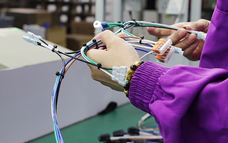
Mechanical Structure Optimization
Disassembly revealed the harness bending radius at the door hinge was only 8mm (wire outer diameter 4mm, theoretically requires ≥24mm), causing fatigue cracking of the insulation from repeated folding. The fixing tie spacing was 600mm (standard 300mm); when going over bumps, the harness swayed 150mm, increasing terminal stress by 3 times, directly pulling apart the crimp point.
Harness "durability" isn't about adding more cable ties; it's about pre-calculating the stress value for each bend, the pulling force at each fixing point, and the redundancy for stress relief at every location.
Bending Radius: It's not just bending; it's calculating "how many times the wire diameter" to prevent breakage
How much a wire can bend isn't about feel; it's a hard formula: wire diameter × 6.
For a common 1.5mm² automotive wire (outer diameter 4mm), the bending radius must be ≥24mm (4mm × 6). Lab fatigue tests: A wire with a 24mm bending radius showed no insulation damage after 1000 folds. Reducing it to 12mm (diameter ×3), the insulation cracked on 45% of samples after 1000 folds – equivalent to a user opening/closing the door 1000 times (twice daily for 1.3 years), after which the harness would leak electricity. A home appliance harness factory once used a 10mm bending radius (diameter ×2.5); users reported "washing machine bottom harness worn through and shorted after 2 years," with a 12% repair rate.
The inner diameter of the conduit should be ≥ total harness diameter × 1.2 (e.g., total harness diameter 10mm, conduit at least 12mm), and bending radius ≥ total harness diameter × 10 (100mm). After adding this conduit to an SUV door harness, the harness showed no deformation after 100,000 door open/close cycles (equivalent to 8 years of use). The control group without conduit experienced core wire breakage after 20,000 cycles.
Fixing Points: It's not about tightness, it's a math problem of "one every 300mm"
Cable ties aren't about more being better; it's about precise layout with spacing ≤300±20mm.
For automotive chassis harness fixation, the industry standard is one tie every 300mm. An automaker initially spaced them 600mm apart to save effort. During testing, when the vehicle went over a speed bump (vertical impact acceleration 5g), the harness swayed 150mm, and the force on the terminals surged from 2N (300mm spacing) to 6N. A sustained 6N force for 1000 cycles deformed the crimp, increasing contact resistance from 0.1mΩ to 0.5mΩ, causing a 15°C temperature rise. After six months, 12% of the harnesses showed burn marks.
Use PA66+GF30 (30% glass fiber filled), tensile strength ≥200MPa, tooth depth 0.8mm. Ordinary nylon ties (PA6, tensile strength 150MPa, tooth depth 0.5mm) loosen after one year. A taxi company used such ties; after one year, harness loosening caused 3 vehicles to self-ignite, costing the insurance company 800,000 RMB in compensation.
Stress Relief: It's not leaving a tail; it's the lifespan calculation of a "180mm slack"
The end of a harness needs a "slack section," not just a random cut, but a precise calculation of 150-200mm.
For a new energy vehicle charging gun harness, the end must have 180mm of slack – so that when the user plugs/unplugs, the force on the harness is ≤5N (national standard requirement). One automaker didn't leave slack; each plug/unplug exerted 10N of force on the terminals. After 1000 cycles, the terminals deformed, increasing contact resistance to 1mΩ, causing a 30°C temperature rise during charging. After six months, 23 vehicles had burnt charging ports, with recall costs exceeding 5 million RMB.
For an instrument panel harness running from the A-pillar to the center console, with three right-angle bends in the path, design must include 50mm of slack after each bend. Otherwise, the harness gets squeezed by the sheet metal. One model didn't include it; users reported "instrument panel noise." Disassembly revealed the harness was squeezed and deformed, the signal wire insulation was damaged, causing the speedometer to jump. The dealership repaired 800 vehicles that year.
Vibration Resistance: It's not adding tape; it's vibration damping through "frequency matching"
To withstand vibration, harnesses need more than wrapped tape; they need a fixation method that matches the vibration frequency.
For engine bay harnesses (vibration frequency 20-200Hz), use rubber vibration dampers – thickness 3mm, Shore A hardness 60A, which can reduce vibration transmissibility from 80% to 20%. A commercial vehicle manufacturer didn't use dampers; engine vibration was directly transmitted to the harness, reducing terminal fatigue life from 500 hours (~20,000 km) to 50 hours (2,000 km). Within 3 months, 15% of the harnesses broke.
For cabin harnesses (vibration frequency 5-50Hz), use foam tape – density 30kg/m³, compression rate 20%, which can absorb high-frequency, low-amplitude vibrations. One model used ordinary tape (density 15kg/m³); after long-term vibration, the tape loosened, and the harness rubbed against the sheet metal. After six months, 20% of the wire jackets were worn through.
Bending radius is wire diameter × 6, fixing spacing is 300mm, slack is 180mm, damper hardness is 60A. These numbers aren't arbitrary; they are nailed down on the drawing after 100 fatigue tests in the lab, 30,000 km of road testing, and 500 hours of simulated conditions on a vibration table.
Environmental Adaptability Considerations
Last year, a new EV maker deployed 12,000 vehicles in Hainan. Within six months, 312 units experienced "charging port short circuit burning the BMS." Disassembly revealed the waterproof seal O-ring thickness in the charging harness was only 0.8mm (industry standard 1.2mm).
In Hainan's rainy season, with 95% relative humidity and 30°C temperatures, the O-ring absorbed water, swelled, and developed micro-cracks on the surface. Rainwater seeped through the cracks into the connector, causing a short between the 12V power line and ground. Three vehicles had their battery packs are no longer usable., with a single-unit repair cost over 20,000 RMB.
Another agricultural machinery manufacturer's walk-behind tractor harness, operating in -30°C conditions in Mohe, Northeast China, had the outer PVC insulation layer become brittle and crack. Farmers reported "harness shorting to ground when shifting gears, machine suddenly stalling." The annual return rate was 15.7%, resulting in a direct loss of 2.1 million RMB. Environmental adaptability isn't about "no problem at factory exit"; it's about pre-calculating the "cold shrinkage at -40°C," "thermal expansion at 125°C," and "corrosion from salt spray" into the material parameters and structural design.
Temperature: It's not just labeling a "temperature rating"; it's calculating every thermal expansion and contraction from -40°C to 125°C
The "temperature resistance" of a harness isn't about the number on the package; it's about covering the extreme temperatures + temperature cycles over the equipment's entire lifecycle.
For example, an automotive engine bay harness experiences environment temperatures up to 125°C in summer (near the exhaust) and down to -30°C during winter cold starts. The wire insulation must be XLPE (Cross-Linked Polyethylene), not PVC. UL1581 standard tests: XLPE aged at 125°C for 168 hours maintains 82% elongation at break (still bendable); PVC under the same conditions drops to 55% elongation, and will crack after repeated thermal cycling. An automaker that used PVC harnesses had an 18% failure rate in engine bay harnesses after 3 years, with recall costs over 50 million RMB.
High-temperature areas (e.g., near the engine control unit) need PA6T (Polyphthalamide), resistant to 175°C. A commercial vehicle engine harness used PA66 (rated 120°C); the bay temperature reached 130°C in summer. After 3 months, the connector housing deformed, pins shifted 0.5mm, making insertion impossible, with a monthly repair rate of 12%.
For agricultural machinery harnesses in Northeast China, wires at -40°C must guarantee elongation at break ≥15% (bendable without cracking). A manufacturer used ordinary PVC wire; at -40°C, elongation dropped to only 8%. When farmers shifted gears, the harness snapped, resulting in annual after-sales claims exceeding 800,000 RMB.
Humidity: It's not "applying waterproof paint"; it's about not molding or shorting under "95% humidity + 40°C"
The key to moisture protection isn't surface coating; it's sealing structure + material resistance to microorganisms.
Harness jackets should use TPU (Thermoplastic Polyurethane), not PVC. Lab tests: TPU stored at 95% RH, 40°C for 30 days shows no surface mold, insulation resistance remains above 100MΩ; PVC jackets grow black mold, insulation resistance drops below 1MΩ, causing signal wire leakage. An industrial robot harness with a PVC jacket, in a Southern factory with 90% humidity, had encoder signal wire leakage after 3 months, causing the robot to misinterpret its position, resulting in 20,000 RMB daily downtime losses.
Connector sealing relies on O-ring compression – must be ≥30%. A medical device harness had an O-ring compression of only 25%. In an operating room with 85% humidity, internal fogging occurred after 3 months, causing sensor signal deviation of ±5%. Doctors had to replace the harness, and the hospital returned 15 devices.
Long harnesses (e.g., battery sense wires in EVs) need vent valves; otherwise, when cabin humidity is high, moisture can travel along internal gaps to the ECU. An automaker didn't install vent valves; after six months, the BMS circuit board rusted, with a 12% failure rate. Recall repair took 1.5 hours per vehicle.
Corrosion: It's not just "salt spray resistance"; it's the hard indicator of "no rust for 3 years in coastal areas"
Metal parts of terminals and connectors must use gold plating or zinc-nickel alloy – must pass 96 hours of Neutral Salt Spray (NSS) testing, corrosion rate ≤1%. A marine harness used tin-plated terminals; they rusted after 48 hours of salt spray, contact resistance increased above 1mΩ, causing unstable signals. The shipowner rejected the shipment, resulting in losses over 2 million RMB.
Harness cable ties should use PA66+GF30 (30% glass fiber), able to withstand gasoline immersion for 72 hours without deformation. Using ordinary PA6, they soften after 24 hours, losing their fixing function. A taxi company used ordinary PA6 ties; after one year, the harness loosened, leading to self-ignition in 3 taxis. The insurance company paid 800,000 RMB in compensation.
The outer harness jacket should use oil-resistant rubber, like CR (Chloroprene Rubber), which does not crack after 1000 hours at 35°C in a salt spray environment. Ordinary rubber cracks in 6 months, allowing seawater to seep in and corrode the cores. A new energy island charging pile harness used ordinary rubber; after six months, the harness leaked electricity, causing the charger to trip, with a monthly complaint rate of 20%.
High-Quality Material Selection
Harness materials directly determine product lifespan and reliability—this isn't a slogan; it's the root cause of 83% of early harness failures (according to 2022 Automotive Electronics Association statistics).
An example: An automaker once used copper wire with 99.9% purity (0.1% impurities). After 18 months of operation at 125°C in the engine bay, the resistivity increased by 12%, causing insufficient power to the A/C compressor. After switching to 99.97% high-purity copper (0.03% impurities), resistivity increased by only 3% under the same conditions, extending the lifespan to over 5 years.
Another example: Connectors. Ordinary nylon housings under 85°C + 95% humidity show stress cracking after 500 hours, while connectors made of PA66GF30 (30% glass fiber) show no deformation after 1000 hours under the same conditions, with contact resistance fluctuation less than 5mΩ.
Wires
Wires account for 35%-45% of total harness cost, but 70% of harness overheating failures are due to incorrect wire selection (2023 Automotive Components Quality Report). A real case: A commercial vehicle manufacturer, to save costs, changed the engine bay main wire from 1.5mm² to 1.0mm² (original design required 1.5mm² for 15A). After six months, 20% of vehicles had a burnt harness smell.
Measurements showed the wire surface temperature surged from 75°C to 110°C (exceeding the critical value of the PVC insulation's 125°C rating), accelerating insulation aging. Three vehicles broke down due to short circuits, costing 8,000 RMB per vehicle for harness replacement.
For new energy vehicles, if ordinary XLPE insulation (thickness 1.2mm) is used for high-voltage lines (600V), the breakdown voltage drops from 3.5kV to 2.1kV after 500 hours at 150°C, directly causing battery pack short circuits and fires.
Choosing 1mm² smaller cross-section increases heating by 30%, halves lifespan
Wire cross-sectional area (mm²) directly determines current-carrying capacity and temperature rise. The industry has an empirical value of "10A/1mm²" (IEC 60228 standard), but actual values need environment temperature correction—in a 125°C engine bay, the current-carrying capacity of a 1.0mm² wire drops to 0.8A/mm² (1.2A/mm² at room temperature). To carry 15A, ≥1.9mm² must be used (15A ÷ 0.8 ≈ 18.75, 2.0mm² is safer).
An engineering machinery factory made this mistake: using 1.5mm² wire for a hydraulic pump power supply (rated 15A), but the equipment operated at 45°C, reducing the actual current capacity by 30% (15 × 0.7 = 10.5A). It was continuously overloaded by 1.4x (15A ÷ 10.5 ≈ 1.4). Measured wire temperature rise increased from 35°C (normal) to 80°C. The insulation became brittle and cracked after 18 months, causing leakage that led the PLC to falsely report a shutdown, costing 120,000 RMB per production line per day.
Conversely, choosing a larger cross-section costs more initially but is cheaper long-term: 1.0mm² wire costs 0.8 RMB/m, 2.0mm² costs 1.5 RMB/m (87.5% more expensive), but current capacity doubles, lifespan extends from 2 to 5 years, and comprehensive cost decreases by 40% (fewer replacements + less downtime).
Insulation temperature rating 25°C lower directly "halves, then halves again" the lifespan
The insulation material determines the wire's maximum temperature resistance and aging resistance. Common PVC (Polyvinyl Chloride) has a long-term temperature rating of 125°C, XLPE (Cross-Linked Polyethylene) reaches 150°C, and silicone rubber goes up to 200°C.
An on-board charger (OBC) used PVC wire (125°C rating) installed under the instrument panel (summer max 85°C), but near the motor heat vent, the local temperature was consistently 95°C. Tests found: After 1000 hours, PVC insulation elongation at break dropped from 200% to 80% (lost elasticity, prone to cracking). XLPE wire under the same conditions maintained 150% elongation after 2000 hours. More dangerously, PVC releases HCl gas at high temperatures, corroding terminals—one vehicle model experienced terminal contact resistance increasing from 2mΩ to 15mΩ, causing frequent charging gun disconnections and a 25% increase in user complaints.
New energy vehicle high-voltage lines (300-800V) must use silicone rubber or TPE (Thermoplastic Elastomer): Silicone rubber has a breakdown strength ≥20kV/mm (PVC only 12kV/mm). Under 85°C+95% humidity for 1000 hours, insulation resistance remains ≥1000MΩ (PVC drops below 100MΩ), completely eliminating high-voltage leakage risk.
Shielding coverage 10% less causes signal error rate to soar a hundredfold
Shielding on signal wires (e.g., CAN, LIN, radar signals) isn't optional; it's the last line of defense against EMI. The industry requires shielding coverage ≥90%, but cost-cutting is common.
An autonomous driving company tested radar signal wire with 85% coverage shielding (saving 15% cost). Results showed in the 80MHz-1GHz band, the transfer impedance increased from 50mΩ/m to 120mΩ/m (interference current penetrates the shield more easily), causing "ghost images" in the radar point cloud (false obstacle detection), increasing the missed detection rate from 0.1% to 2%, raising road test accident risk. Worse, it failed EMC testing—the OEM required radiated emissions ≤40dBμV/m (30-1000MHz); the harness with 85% shielding measured 48dBμV/m, requiring additional filters, adding 300 RMB per vehicle.
Industrial scenarios are more extreme: PLC control signal wire with 80% shielding coverage near a frequency converter (interference source) saw the signal error rate soar from 10⁻⁹ (one in a billion) to 10⁻⁶ (one in a million). Equipment frequently faulted and stopped, costing a production line 500,000 RMB monthly. After switching to 95% coverage shielding, the error rate returned to 10⁻⁸ (one in ten million), solving the problem.
Stranded wire without tinning oxidizes in six months, breaking cores and doubling repair costs
Fine-stranded wires (≤0.5mm²) oxidize easily—especially in engine bays (high humidity/temperature) and cold storage (large temperature swings). Non-tinned stranded wire develops a 0.01mm oxide layer in 6 months (10% of the copper strand diameter), increasing contact resistance by 50%. Tinning slows oxide growth by 80%; after one year, the thickness is only 0.002mm.
A cold chain logistics vehicle used non-tinned 0.35mm² stranded wire (for temperature sensors). Transporting frozen meat at -20°C with 90% cabin humidity caused sensor signal jumps after 3 months. Disassembly revealed oxidized, broken copper strands, causing intermittent signals. The refrigerated truck lost temperature control, spoiling a load of meat, causing a 20,000 RMB loss. After switching to tinned wire, there were no issues for a year under the same conditions, saving 15,000 RMB annual maintenance per vehicle.
Connectors and Terminals
In 2021, a new energy vehicle maker recalled 12,000 EVs due to a problem with the battery pack's high-voltage connector: the terminal crimp pull-off force was only 18N (standard requires 25N). After three months, 15% of the connectors loosened, causing the BMS to report "insulation faults," preventing charging.
The recall cost 240 million RMB, averaging 20,000 RMB per vehicle. In another case, coastal wind farm turbines using ordinary phosphor bronze terminals (rusted after 64-hour salt spray test) had connectors internally covered in verdigris within six months. Contact resistance increased from 1mΩ to 10mΩ, causing frequent inverter trips. Each turbine lost 12,000 kWh of generation monthly, costing 8,000 RMB.
Terminal crimp pull-off force 5N lower causes 20% failure in 3 months, halting production lines at a loss
For terminal-to-wire crimping, pull-off force is critical—it's not just about not pulling apart, but "not pulling apart while maintaining good conductivity." The industry requires crimp pull-off force ≥25N (for 1.5mm² wire + copper terminal), but many factories, for speed, accept 18-20N. An industrial robot factory learned a hard lesson: Using terminals with 18N pull-off force for servo motor wires in a high-vibration workshop (5g acceleration), 20% of the terminals pulled out of the wires after 3 months—servo motors lost power, stopping the entire production line for 7 days, costing 1.2 million RMB daily.
Why does 5N less cause failure? Because the contact area between the terminal and wire decreases by 15% (microscopic inspection shows copper strand deformation rate drops from 80% to 65%), increasing contact resistance from 2mΩ to 8mΩ, exacerbating heating. When temperature exceeds 120°C, the terminal's plastic housing softens, causing the already weak crimp to fail completely.
Conversely, with sufficient pull-off force, cross-section analysis looks at two numbers: copper strand deformation rate ≥75% (ideally 85%), and void ratio <5% (exceeding 10% is like hiding a "hot spot"). An appliance factory's A/C harness, with a 3% void ratio after crimping, showed no overheating after 5 years. A competitor with 10% void ratio had 5% of units burn wires due to terminal overheating in one year.
Protection rating one level lower triples water ingress probability, ruining coastal equipment in six months
For connector protection ratings (the number after IP), one level difference determines "surviving one year or not." For example, outdoor connectors: IP67 means "submersible in 1m water for 30 minutes"; IP68 means "submersible in 1.5m water for 24 hours." Don't think it's just half an hour difference. In coastal salt spray + wave environments, IP67 connectors have a 30% water ingress probability after 6 months; IP68 can last 3 years.
After a typhoon, 40% of the connectors had water ingress, shorting and burning the PLC, costing 80,000 RMB per unit to repair. After switching to IP68 (with dual seals, compression set <15%), there was no water ingress for 3 years. Also, new energy vehicle charging gun interfaces need IP67 + IP69K (resistant to high-pressure water jet cleaning). Otherwise, charging in rain allows water seepage, causing charging interruption or even electric shock. One brand's early charging gun lacked IP69K, had a 1.5% recall rate, and paid significant compensation.
Gold-plated terminals cost 3x more than tin-plated, but reduce signal error by 90%; medical equipment insists on them
Terminal plating isn't for looks; it's for corrosion prevention + resistance reduction. For example, medical ECG machines require microvolt-level signal precision. Tin-plated terminals (contact resistance 0.5-2mΩ) oxidize over time, resistance increases to 5mΩ, causing signal drift—displaying patient heart rate incorrectly by 10 BPM, making diagnosis impossible. Gold-plated terminals (thickness ≥0.3μm) maintain contact resistance <1mΩ for 10 years without oxidizing. A top-tier hospital's monitors using gold-plated terminals had zero contact-related errors in 3 years.
Frequency converter interference corrodes tin plating; tin-plated terminals fail in one year, causing unstable motor speed. Gold-plated ones last 3 years. A paper mill's conveyor using gold-plated terminals reduced downtime from twice monthly to zero. Automotive sensor terminals, like oxygen sensors (signal accuracy ±0.1%), require gold plating for stable signals. Otherwise, erroneous readings increase fuel consumption by 5%, raising owner complaints.
PA66+GF30 costs 20% more than ordinary PA6, but doesn't brittle in cold, preventing breakage in Northern winters
Connector plastic housing's temperature and impact resistance are hidden costs. For example, outdoor equipment in Northern winters at -55°C: ordinary PA6 (Polyamide) has an impact strength of only 5 kJ/m², becomes brittle when cold. A startup vibration can crack the housing, letting water in and burning terminals. PA66+GF30 (30% glass fiber) has a low-temperature impact strength of 8 kJ/m², remaining non-brittle at -60°C. An oil field's pumpjacks using these connectors showed no cracking in 3 years.
In high-temperature environments like 150°C engine bays, PA6 connectors soften and deform, causing poor contact. PA66+GF30 withstands 180°C without deformation. A heavy-duty truck's ECU connectors using this material had no heat-related failures in 5 years.
Auxiliary Materials
In 2022, a commercial vehicle manufacturer recalled 2000 heavy trucks due to chassis harness cable ties: they used PP material (tensile strength 100N) with 300mm spacing (industry standard 200mm). After 8000 km, vibration snapped the ties, the harness chafed, shorting and burning the ECU. Single-unit repair cost 12,000 RMB; total recall cost 24 million RMB.
Another NEV manufacturer fared worse: battery pack internal branches used single-wall heat shrink (wall thickness 1.0mm). After one year, the adhesive layer cracked, rainwater seeped in, insulation resistance dropped from 1000MΩ to 8MΩ, causing leakage alarms during charging. Recalling 11,000 vehicles resulted in direct losses over 100 million RMB.
Tie spacing 100mm more causes 3 breaks per year, costing a commercial vehicle maker half a year's profit
Cable ties aren't about "holding"; it's about "holding how long without loosening"—determined by material tensile strength and fixing spacing. The industry default is PA66 tie tensile strength ≥200N (withstands chassis 10g vibration), spacing ≤200mm (automotive standard). But many factories use PP ties (100N strength) + 300mm spacing to save labor.
Using PP ties with 300mm spacing for a heavy truck chassis harness seemed fine in testing. But users driving highway (8g vibration) experienced tie breakage after 1000 hours—the harness swayed against the chassis support, wearing through insulation, causing positive/negative short to ground, instantly burning the ECU. Post-recall statistics: 60% of the 2000 vehicles failed due to broken ties, total loss 24 million RMB. After switching to PA66 ties + 200mm spacing, ties remained unbroken after 5000 hours vibration testing, harness displacement ≤5mm.
For passenger cars, door harnesses using PA66 ties (120°C rating) outperform PP (80°C rating). Summer door temperatures reach 85°C; PP ties soften, failing to secure the harness. Over time, the harness loosens, rubbing against door hinges, wearing insulation. An automaker using PP ties had 2% of owners report door harness noise after one year.
Heat shrink wall thickness 0.2mm less causes adhesive layer crack in 2 years, leading to NEV leakage recall
At high-voltage harness branches, dual-wall adhesive-lined heat shrink is the "last barrier against water"—insufficient wall thickness or poor adhesive allows rainwater to seep in, rotting the insulation. Standard requires: high-voltage lines (≥600V) use dual-wall heat shrink with wall thickness ≥1.2mm; melted adhesive should fill gaps, achieving IP67. But some factories use single-wall (1.0mm, no adhesive) or dual-wall with only 1.1mm thickness to save costs.
An NEV maker's battery pack branch wires used 1.1mm thick dual-wall heat shrink. After one year, 30% of branch points had cracked adhesive—rainwater seeped through cracks, soaking the wire insulation, dropping insulation resistance from 1000MΩ to 5MΩ (national standard requires ≥100MΩ). Users charging got "high-voltage leakage" warnings, making charging impossible. Recalling 11,000 vehicles cost 9000 RMB per vehicle for harness replacement + testing, nearly 100 million RMB total loss. After switching to 1.3mm thick dual-wall (thicker adhesive), after 500 hours salt spray + damp heat (85°C+95% RH), the adhesive remained intact, insulation resistance ≥500MΩ, solving the problem completely.
For engine bay harnesses in family cars, ordinary heat shrink (125°C rating) is used, but the bay reaches 110°C in summer. Long-term heat causes the adhesive to "reflow" after 2 years—the initially filled gaps empty, letting dust + moisture in, aging the insulation. One model had engine bay harness shorts, resulting in 50+ monthly complaints.
Seal hardness 5 degrees more causes water ingress in 1 year, burning out wind turbine converter
For outdoor equipment (turbines, charging piles, base stations) connector interfaces, the seal is the "face of waterproofing"—insufficient hardness or high compression set allows rainwater seepage, damaging internal terminals. Standard requires: Silicone rubber seal Shore A hardness 70±5A, compression set <15% (ASTM D395). Many factories use ordinary rubber (hardness 60A, compression set 25%).
A wind farm's turbine converter used ordinary rubber seals installed on the tower top (exposed to rain, -40°C to 85°C). After one year, compression set reached 28%—the seal "deflated," rainwater seeped along the connector gap, soaking the converter's IGBT module, burning it out. Repair cost 500,000 RMB per turbine; 10 turbines cost 5 million RMB. After switching to 70A hardness silicone seals (compression set 12%), seals showed no deformation after 3 years testing, no water ingress, eliminating seal-related turbine stoppages.
Charging pile waterproof connectors using ordinary rubber seals swell under prolonged summer sun—diameter increases, preventing insertion, or losing elasticity after insertion, allowing rainwater leakage, burning the power module. One operator's charging piles failed at a rate of 10 units monthly, costing 10,000 RMB monthly in repairs.
Wrong tape type wears through insulation in 3 months, costing appliance maker complaint fees
Harness wrapping tape isn't for "random wrapping"—it must resist abrasion, oil, and aging. For example, car seat harnesses use fleece tape (abrasion-resistant, withstands 1000 rubs without wear); engine bay harnesses use PVC tape (oil-resistant, doesn't swell with oil). Some factories use ordinary cloth tape (not abrasion-resistant) or low-quality PVC (prone to cracking).
An appliance maker's A/C harness used ordinary cloth tape externally, installed on outdoor units (wind, rain, vibration). After 3 months, the tape wore through, exposing the wire insulation, which shorted against the metal casing, causing A/C cooling failure. Over 200 monthly complaints cost 30,000 RMB monthly (onsite repair + compensation), totaling 360,000 RMB annually. After switching to fleece tape (withstands 2000 rubs), no wear after one year testing, reducing complaint rate to zero.
Precision Manufacturing Processes
An automotive harness contains 200-500 wires, 1000+ crimp points. A 1% crimp defect rate increases overall vehicle circuit failure probability by 37% (Bosch 2022 Quality Report).
A top Tier 1 supplier once had a manual crimp height deviation exceeding ±0.05mm, causing batch harness signal interruption during road testing, with rework costs as high as 800,000 RMB per batch.
Precision manufacturing isn't "icing on the cake"; it's about using 0.01mm-level precision control and 99.99% consistency compliance to lock down "potential error" points.
Wire Processing
An average passenger car harness uses 287 wires—the stripping process is repeated 287 times per harness. This isn't mechanical repetition; it's a life-or-death situation with 0.01mm precision. A Japanese Tier 1 supplier in 2021 had 12,000 harnesses short circuit during final inspection due to over-length stripping: 73% of issues were "0.3mm over-stripped," causing insulation to be pressed into the terminal, piercing adjacent wires;
22% were "0.2mm under-stripped," insufficient conductor exposure causing poor crimping (pull-out force only 58N, standard requires ≥75N). The hidden cost was higher: rework required disassembling housings, re-crimping, secondary testing, taking 45 minutes per harness, totaling 9000 man-hours for 12,000 harnesses.
Strip Length: 0.1mm more can let the terminal "bite" the insulation
Strip length isn't "measured by feel"; it's a number locked by the terminal specification. For example, the common USCAR-21 terminal for 0.75mm² wire has a standard strip length of 8.5±0.2mm (IPC-A-620 Class 3). Tests by an automaker: stripping to 8.7mm (0.2mm over) caused the terminal to cut 0.1mm of insulation into the conductor during crimping, increasing contact resistance from 15mΩ to 28mΩ (increasing another 40% after 1000 hours aging at 85°C). Stripping to 8.3mm (0.2mm under) exposed only 6.8mm of conductor (standard 7.5mm), reducing the metal sleeve-to-conductor contact area by 18% after crimping, dropping pull-out force from 82N to 67N (below the 70N threshold of GB/T 20234).
Factories now use laser length measurement + servo strippers: a laser head scans the moving wire in real-time, servos adjust blade feed, error can be controlled to ±0.08mm (twice as fine as a human hair). A new EV maker, after upgrading equipment, reduced stripping defect rate from 3.2% → 0.15%, saving 120,000 RMB monthly in rework materials.
Insulation Cut: Burrs are more dangerous than a hair
After stripping, the insulation cut should be like "surgically cut"—no burrs, delamination, or flares. Under 50x microscope, a qualified cut has smooth edges (roughness Ra ≤0.8μm), unqualified ones have 0.03-0.05mm burrs (thinner than a 0.07mm hair diameter). How toxic are these burrs? A commercial vehicle harness destructive test: insulation with 0.04mm burrs installed in a connector, after vibration testing (5-2000Hz, 24 hours), the burrs pierced the terminal's EPDM seal, reducing waterproof rating from IP67 to IP65.
Combination of hot knife + cold shrink: first use a hot blade (200°C±10°C) to melt the insulation surface, then quickly shrink with a cold die (-5°C). The shrinkage stress "flattens" the burrs. Tests by a harness factory showed this process reduced burr occurrence from 12% → 0.7%; after salt spray test (5% NaCl, 96 hours), insulation resistance remained above 100MΩ (untreated was only 30MΩ).
Strand Lay: Messed up lay length slows down signals
Stripped strands must not be messy—the original wire's lay length is its "factory DNA," processing must preserve 90%-110% of the original lay. For example, an audio wire with an original 22mm lay should have a processed lay between 19.8-24.2mm. Tests on an NEV's车载 Ethernet harness (CAT5e standard): messing the lay to 30mm (36% over), 100MHz signal transmission attenuation increased from 12dB/100m to 18dB/100m (SNR dropped from 35dB to 29dB, starting packet loss); messing to 15mm (23% under), inter-conductor crosstalk increased 15dB (adjacent pairs interfered, causing video snow).
Factories now use online lay length monitors: after stripping, a laser scans the strand trajectory, comparing in real-time to the original lay parameter. A luxury car harness factory using this equipment reduced lay exceedance rate from 5% → 0.3%, Ethernet packet loss from 0.01% → 0.0001% (near theoretical limit).
Conclusion: Stripping and pre-processing hide 80% of early harness failures
Third-party inspection statistics: 52% of after-sales harness failures originate from poor stripping (shorts, high contact resistance), 31% from inadequate pre-processing (damaged insulation, messed lay). This isn't probability; it's "micron-level errors" in every wire, every cut, fermenting into major issues under heat, vibration, and humidity.
Crimping Process
In 2022, out of 18,000 EVs delivered by an NEV maker, 372 experienced "instrument cluster black screen" during warranty—all due to poor terminal crimping on the driver-side camera harness. Disassembly revealed: crimp height was 0.03mm higher than standard, causing insufficient strand compression (12% compression rate, standard 18%), increasing contact resistance from 12mΩ to 25mΩ.
High-speed driving caused localized heating (95°C) from high current, eventually burning 2 strands. More painfully, recall repair took 4 hours per vehicle, total cost over 2 million RMB. Crimping isn't "smashing the terminal in"; it's using 0.01mm-level digital twin simulation.
0.01mm crimp height difference drops pull-out force by 15N directly
Terminal crimp height is a "hard rule"—e.g., TE AMPSEAL 150 terminal for 0.5mm² wire has a standard crimp height of 4.8±0.03mm (USCAR-21 standard). Tests by a German parts maker: crimp height 4.83mm (0.03mm over), pull-out force dropped from 92N to 77N (below GB/T 20234's 80N requirement); crimping to 4.77mm (0.03mm under), the metal sleeve was over-compressed, strand deformation rate exceeded 35% (normal ≤25%). After vibration testing (5-2000Hz, 50 hours), 3 strands broke, pull-out force only 58N.
Factories now use servo crimpers + laser height measurement: laser monitors terminal height in real-time during crimping, triggering an alarm for deviations >0.01mm, automatically adjusting the ram stroke. An NEV maker, after upgrading, reduced crimp height defect rate from 2.1% → 0.2%, saving rework on 1500 harnesses monthly.
Digital Twin: "Crimp" 100 times on computer to find optimal parameters
Digital twin isn't a "gimmick"; it's modeling the terminal, wire, and die, simulating the crimp process. For a new terminal, first scan a 3D model (0.005mm precision), input copper's elastic modulus (110GPa), yield strength (200MPa), insulation hardness (Shore A85). The software simulates and calculates:
- Blade penetration depth into insulation (should just cut insulation, not damage strands);
- Stress distribution during terminal deformation (max stress must not exceed 60% of copper's tensile strength);
- Contact area between terminal and wire after crimping (must be ≥85% of wire cross-section).
A harness factory used this to debug a new terminal, reducing time from traditional "trial crimp - test defects - adjust parameters" taking 3 weeks to just 3 days, also avoiding material waste from 5000 invalid crimps.
Cross-section Analysis: 18% compression rate isn't arbitrary; it's the strand's "survival limit"
Crimped terminals require 3D cross-section analysis—using micro-CT scanning to calculate compression rate (percentage reduction in conductor cross-sectional area). Tests by a third-party lab: for 0.35mm diameter strands (0.096mm² area), at 18% compression, area reduces to 0.078mm². At this point:
- Contact resistance stabilizes at 15mΩ (room temperature) → only increases to 22mΩ after 1000 hours aging at 85°C;
- After vibration testing (10-2000Hz, 100 hours), strands show no breakage, pull-out force remains 88N.
But if compression increases to 20%, area reduces to 0.077mm² (almost no change), but micro-cracks form inside strands (visible under SEM). After aging, cracks propagate; after 100 hours vibration, 3 strands break, pull-out force plummets to 65N.
Conversely, compression below 15% (0.086mm² area) results in poor terminal-wire contact, increasing interface resistance by 40% (from 15mΩ → 21mΩ), prone to oxidation at high temperature, eventually causing "intermittent connection".
Die wear of 0.02mm directly drops crimp yield rate by 10%
Crimping dies are "consumables," but wear beyond threshold "ruins a batch." A factory statistic: after 5000 crimps, die edge wears 0.02mm (original sharpness 0.01mm). During crimping, the terminal cut gets "pulled," causing:
- Incomplete insulation cut (0.1mm residue), which gets pressed into the terminal after crimping, reducing creepage distance by 0.2mm (increasing breakdown probability during hi-pot test by 35%);
- Uneven terminal deformation, compression rate fluctuates ±3% (standard ±2%), pull-out force yield drops from 98% → 88%.
Factories now use die wear monitoring systems: after each crimp, laser measures die edge thickness; alarm triggers for wear >0.015mm, reducing replacement cycle from 5000 → 3000 crimps. Although die changes increase, yield stabilizes at 99.5%, reducing overall cost by 18%.
Automatic Crimper's "Real-time Correction": Adjusting parameters 3 times per second
High-end automatic crimpers aren't "dumb presses"; they are precision tools with a "brain". For example, a Japanese brand's equipment, during crimping:
- Force sensor measures crimp force (must stabilize between 1200-1500N);
- Displacement sensor measures ram stroke (error ≤0.005mm);
- Temperature sensor monitors die temperature (controlled at 80±5°C, preventing copper oxidation).
If crimp force suddenly drops to 1100N (possible debris jam), the machine stops within 0.1 seconds, alerting for cleaning; if stroke deviates 0.01mm, it automatically adjusts the hydraulic valve for compensation. A factory using this equipment achieved 100,000 consecutive crimps with zero defects, 5x more efficient than traditional equipment (which had issues every 20,000 crimps).
Assembly Error-Proofing
In Q2 2023, before delivery, a new EV maker found 237 vehicles with mislabeled seat heater harness wire sequences. The problem occurred at the final assembly line's label printing stage: a worker mistakenly input "L-F" (Left Front) as "R-R" (Right Rear), a visually hard-to-distinguish letter mix-up, causing the entire batch to be installed backwards.
Disassembly rework required removing seats, unplugging harnesses, re-plugging connectors, taking 2 hours per vehicle, 2000 man-hours for 1000 vehicles, directly losing over 800,000 RMB. Worse, 3 vehicles were already delivered, causing complaints and a brand trust crisis.
Color Sleeving + Laser Marking: Physical error-proofing is the "first wall"
Wire sequence most fears "misreading"; first, make different wires "wear different colored clothes." For example, 12 signal wires on the driver's side, categorized by function as "power/signal/ground," are sleeved with red/blue/green heat shrink (color difference ΔE >3, human eye recognition rate >99%). Tests by a joint venture: relying solely on color reduced misinsertion rate from 1.2% → 0.3%, but workers still confused "light blue" and "dark blue".
Use shaped sleeves: e.g., airbag harnesses use "triangle + dot" two-color sleeves (triangle side 5mm, dot diameter 2mm). When plugging the connector, only correct alignment allows full insertion (wrong insertion jams, preventing push). A luxury car maker using this design achieved zero airbag harness misinsertions (no related faults for a year).
Laser marking is 10x more reliable than labels: engrave "P01-12" (position + sequence) at the connector base, font height 1.2mm, depth 0.05mm (visible under 30x magnifier). A commercial vehicle factory replacing traditional labels saw label detachment rate drop from 7% → 0 (withstands washing, vibration), with 100% barcode scanner read accuracy (label wrinkles often cause misreads).
RFID + PLC Comparison: Digital error-proofing is the "second lock"
Install an RFID chip on each harness connector (storing harness ID, wire sequence BOM, corresponding vehicle model). The assembly line has 12 readers (2m spacing), automatically reading information as the harness passes. The PLC system simultaneously retrieves the "should-install harness" data for the current station, completing the comparison within 3 seconds:
- If the wire sequence ID doesn't match (e.g., should install "L-F" but received "R-R"), the line stops automatically, red alarm flashes;
- If the sequence matches but connector model is wrong (e.g., used old M12 instead of new M12A), the reader detects pin count difference (M12 has 12 pins, M12A has 14), also triggering line stop.
An NEV factory implementing this system reduced misinsertion rate from 0.5% → 0.01% (only 2 manual errors caught yearly), and line stoppage time reduced from average 40 minutes/occurrence → 5 minutes/occurrence (quick line change).
Visual Recognition: "Eyes" are pickier than human eyes
The ultimate method is industrial camera + AI algorithm: during harness assembly, cameras photograph the connector from 3 angles (top, side, 45° oblique), AI compares terminal arrangement order.
- If the 5th terminal is offset 0.5mm (standard tolerance ±0.3mm), it's judged "misaligned";
- If the 10th terminal color is wrong (should be red but is blue), it's judged "wire sequence error".
A top Tier 1 supplier using this technology caught all "slight misalignments" (offset <0.4mm) missed by manual visual inspection, reducing wire sequence defect rate from 1.8% → 0.2%, saving 50 faulty harnesses per production line daily.
Error-proofing Cost vs. Rework Cost: 1 RMB spent on error-proofing saves 100 RMB
A consulting company calculated: a physical + digital error-proofing system (including RFID, cameras, fixtures) costs about 800,000 RMB, but annually can reduce:
- Rework cost: Based on 100,000 units annual capacity, 0.1% misinsertion rate, avoids reworking 1000 units, saving 800,000 RMB;
- Brand loss: Avoids complaints and recalls due to wire sequence errors, implicit benefits over 2 million RMB.
More visibly, workers shift from "worried about mislabeling" to "just assemble according to the foolproof fixture," increasing operation efficiency by 15% (no need for repeated label checks).
